Groupwork: measuring Kerf
Group members
- Achille
- Anssi
- Hannu
- Jari
In the group work we tried to measure the Kerf of two materials using laser cutter and also played a little with its settings for cutting and engraving. It was done in collaboration with Achille, Anssi, Hannu and Jari.
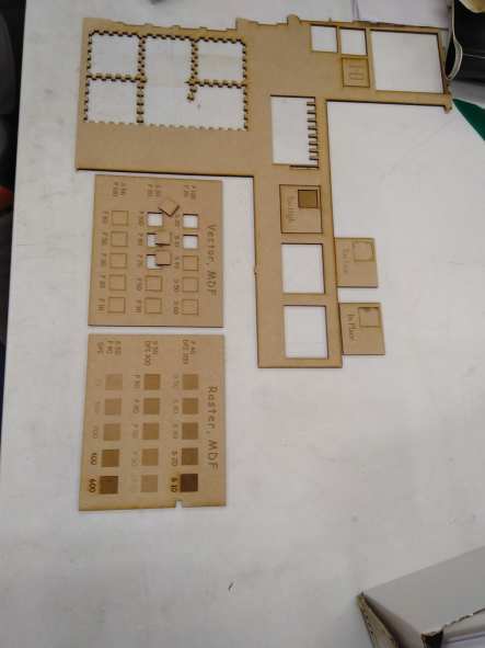
Local instructor Behnaz had already made files for us to test the laser cutter for saving our time to actual tests. Design contained engrave for each piece of the settings.
However, for the cases, where material is not ready for use, its essential to know how to prepare test-set by yourself. To make the tests parts (if not readymade material available) you have to design an image in Inkspace with eight slots of varying sizes that should be equally positioned across a rectangular diagram. The width of each slot should be 10mm minus the number indicated on the base of the slot. Then you need also have another rectangular piece, which is 10mm wide and which will be used to measure the kerf.
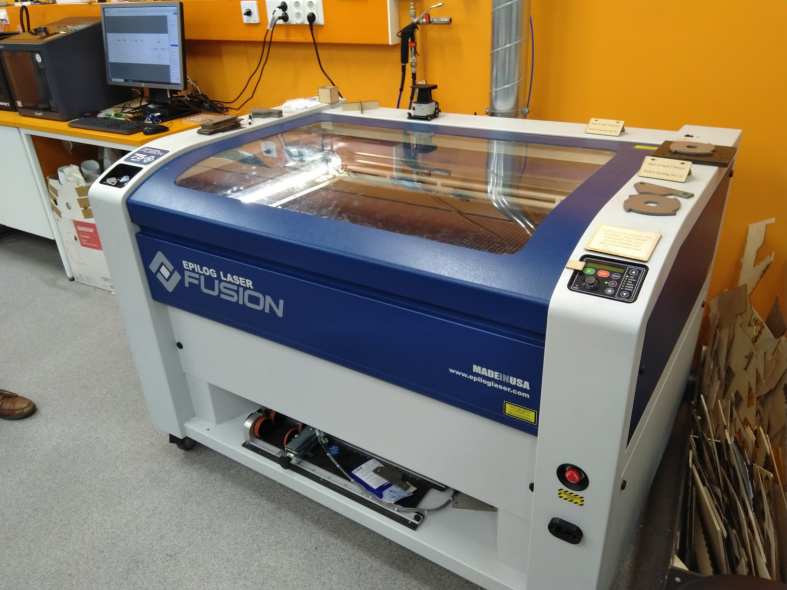
We went to the Epilog Fusion laser cutter, and we made sure that both the ventilation and the air pressure were open. We started to prepare the machine for vectorcut MDF. After this we used a Epilog Mini laser cutter for raster MDF.
First we cut the frames for the vector and raster tests that contained information which settings we were supposed to use for each square. Everyone used a laser cutter in turns to learn how to pick files, using print software and the machine.This helped a lot with individual assignments.
In the actual we had three different cutting procedures to be done:
In the vector test we used Epilog Fusion laser to cut squares out of the MDF with different settings as you can see from the table and our description below.
| Power 100, Frequency 20 | Speed 20: cut ok, risk of burning | Speed 10: cut ok, risk of burning | Speed 40: no cut | Speed 50: no cut | Speed 60: no cut |
| Speed 20, Frequency 20 | Power 100: cut ok | Power 80: cut ok | Power 70: cut ok, optimum | Power 50: not cut anymore, traces visible | Power 30: not cut anymore, traces visible |
| Speed 50, power 100 | Frequency 60 no cut, but line is blurry | Frequency 50 no cut | Frequency 30 no cut | Frequency 20,no cut | Frequenc 10, no cut, but line is clear |
Based on our experimentations its clear that when you have high power and slow speed, it’s risk to burn MDF. Furthermore, even if you increase the speed of cutter, there is no cut result when power is at it’s highest setting.
On the otherhand, when speed and and frequency are pretty low (20), cutting is successul if power setting is high enough. However, when you decrease power to half of maximum (50) there are just traces visible, without successful cut.
In our third experiment, we set up speed to half of maximum (50) and power to maximum to see wha’ts role of frequency. Well, cutting wasn’t succesfull with any of the used frequency settings (variable which was changed during the process).
Without any magnifying device role of frequency in that test is difficult to see. But with “luuppi” it was possible to see that cutting was close to be trough the mdf. However, changing the frequency didnt change output very much.
| Power 40, DPI 300 | Speed 50 (not ok) | Speed 40 (not ok) | Speed 30 (ok) | Speed 20 (almost burned) | Speed 10 (burned) |
|---|---|---|---|---|---|
| Speed 50, DPI 300 | Power 90 (good) | Power 80 (good) | Power 50 (ok) | Power 30 (not ok) | Power 10 (not ok) |
| Speed 50, Power 40 | DPI 75 (not ok) | DPI 150 (not ok) | DPI 200 (not ok) | DPI 400 (not ok) | DPI 600 (not ok) |
In our raster test, we noticed that when you have average speed (50) and normal DPI (300) rasterizing is best. It was possible to get best results in tests with power settings 90-80 in this condition. Other power values didn’t procude as good result.
However, when you change power to 40 and keep DPI as 300 and change speed values in the test, most of rasterized squares are not adequate. Same is in the condition where speed is 50 and power 40, but DPI is changed. If DPI is below 300 quality of raster is not good and if you increase value 400 or over, it will over-rasterize your design.
So, good rule of thumb based on this test is to keep DPI in the default value (300), speed in average condition and use quite high speed (90 or 80).
First we created a file with our local instructor for this with Inkscape. Every rectangle was set to be 5mm wide so the whole ladder was 100mm wide.
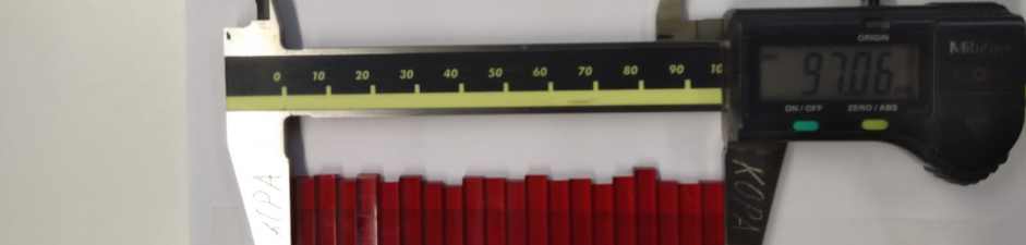
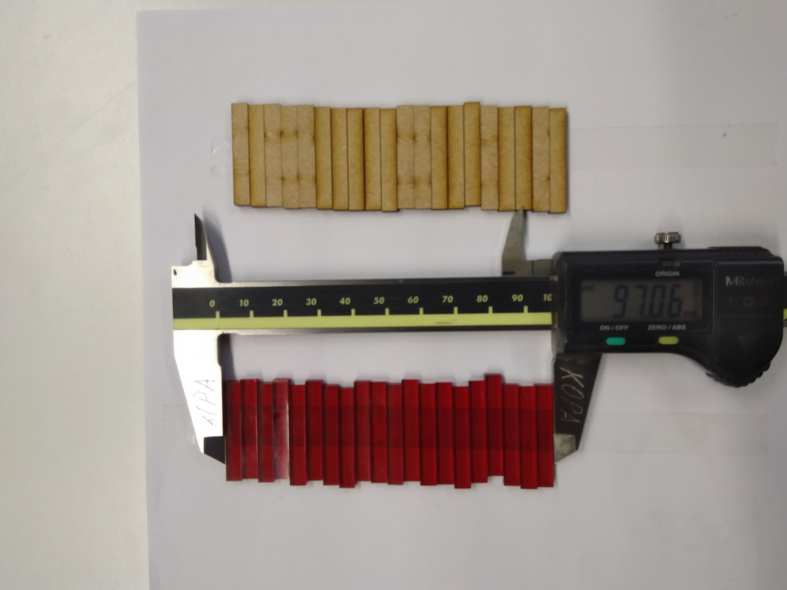
In the kerf test we used Epilog Fusion laser to cut 20 rectangles out of the MDF and acrylic. Every piece was set to 5mm width and for testing kerf we set them in line on double sided tape and measured the length.
Kerf test was done with following settings: MDF 3mm, S=20, P=100, F=20 and Acrylic, S=12, P100, F100.
It was interesting to notice that 3 groups had different results for kerf. This method there could easily be small mistakes made by users. Formula for calculating kerf in this case is: (original size - size after cut)/20=kerf. Average of results for three groups were for MDF 3mm 0,07mm and for Acrylic 0,13mm.
It was interesting to notice that 3 groups had different results for kerf. Although with this method there could easily be small mistakes made by users. Formula for calculating kerf in this case is: (original size - size after cut)/20=?.
After making all of tests we discussed the differences these settings make and calculated kerf. Changing speed, frequency and power seem to make a difference.