Week 9: input devices
individual assignment:
measure something: add a sensor to a microcontroller board that you have designed and read it
group assignment:
probe an input device's analog levels and digital signals
Group assignment
Worked with Achille, Hannu, and Jari in group assignment this week. We used Fritzing to test analog levels and digital signals.
Our group's documentation can be found from Jari's site.
Individual assignment
Our lab is currently closed due to covid-19. Because of this I will design PCB in advance for the future when we lab is open again, but will test principles with Arduino UNO already.
Local instructor Ari advised that I could test a temperature sensor, LM335Z for this. I began my adventure with the datasheet to see pin-layout and other information. This sensor has 3 pins, which are from left to right: ADJ (1), V+ (2) and V- (3). It's output voltage is around 3V.
I found out that it could be possible to run on UNO without using breadboard. I didn't quite understand how, but gave it a go. After a while found even a guide how to do it from Learning About Electronics.
According the guide this would be possible to do with only a UNO, a lm335 sensor, jump wires and a usb cable. I am not really understanding how it is going to get power with only these two.
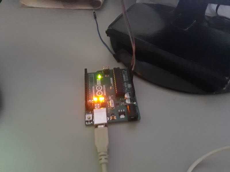
I connected pin2 to a analog input (A0) and pin3 to a ground. Pin1 which is for adjusting can be left as it is not required.
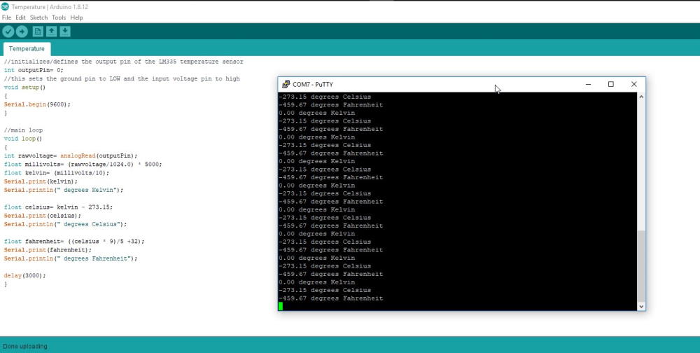
I uploaded the code from the guide to see if this setup actually works. And it does not. I searched more information about this but could not get it to work without a breadboard and resistor.
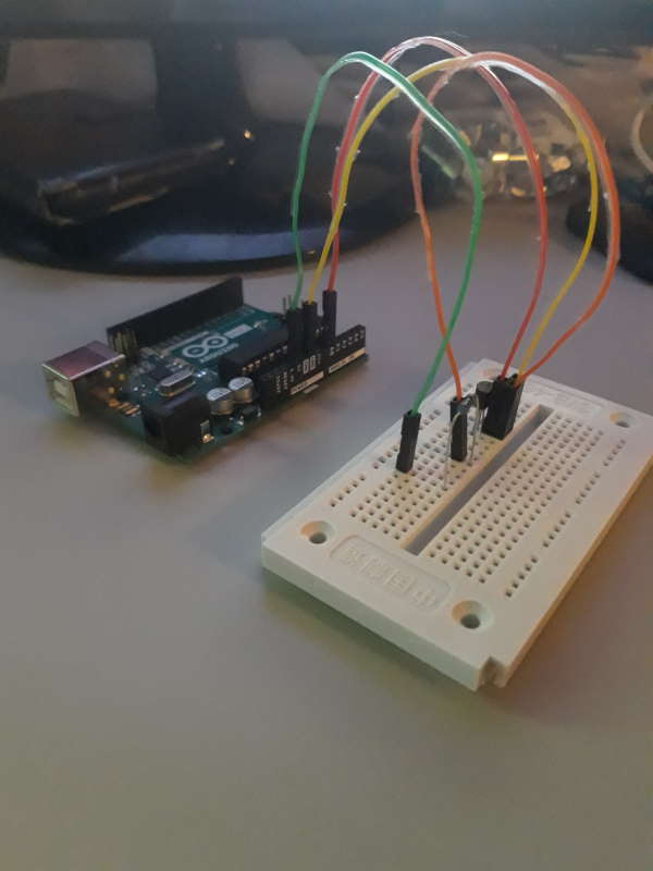
I used 2k ohm resistor and breadboard with this setup. Obviously I saw on the forums which resistor was mostly advised to use, but I wanted to understand why and how to calculate it in the future. With Ohm's law it is possible to calculate voltage, current and resistance required if two of these are known. In this case I am using 5V input from the arduino and LM335 uses 3V. I also know that operating current is 1mA. With this information I can use R = V/I so (5-3)/1=2. Since the current is 1mA (0.001A) instead of 1A the resistor needs to 2000 ohms instead of 2 ohms.
There seems also be a Ohm's law calculator to use.
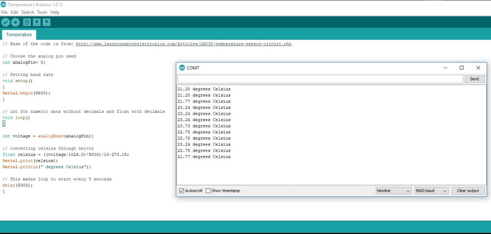
I changed the code a little bit while testing if the sensor works since I don't have need for other prints than celsius. This time sensor worked and it was pretty accurate.
Also started to use Serial monitor (Shortcut: CTRL + SHIFT + M) to see the results instead of PuTTY. Serial monitor can be found under the Tools dropdown menu.
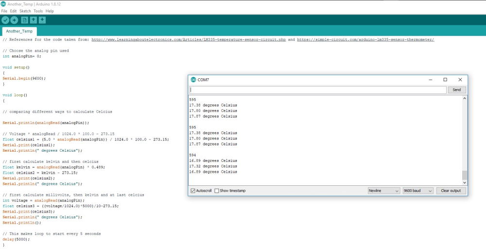
I wanted to see another ways to calculate the temperature and also verify that this code actually works. Found another example and a formula which I filled. After uploading again and opening Serial monitor I noticed that all of these gave different results except on some voltages first and last were equal.
ADC
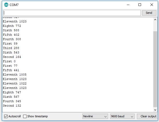
In these previous programs an Analog to Digital Converter (ADC) is the thing. This feature converts an analog voltage on a pin to a digital number. For example Arduino UNO R3 uses ATmega328P microcontroller which has a 10-bit ADC. This means it can detect analog levels between 0 and 1024 (2^10). Because temperature sensor doesn't show conversion that clearly I wrote short code to control the analog levels by using potentiometer. I am also going to use potentiometer in my final project so this was good practice for it as well.
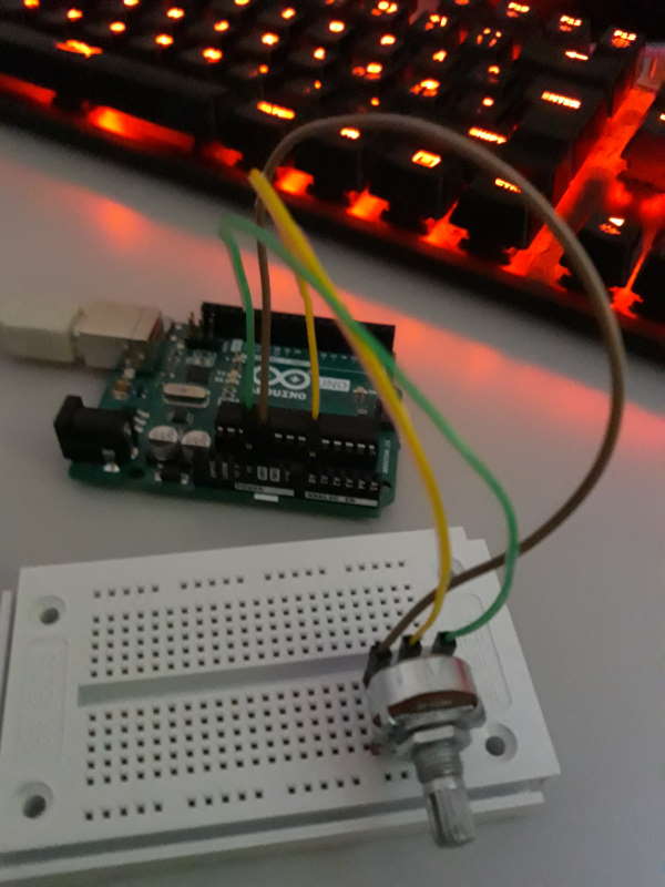
Arduino UNO and potentiometer. Potentiometer has 3 pins which are GND, Output and Input.
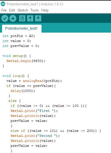
Short sample of the code for potentiometer. With this I wanted to test how to detect certain ranges of values after rotating potentiometer. This worked perfectly for what I wanted to do outside of the fact it takes so many lines of code.
Short video showing the code in action.
Final project
I used pushbuttons and potentiometers on my final project and made a board for them. Documentation for these can be found from my final project page.
Files
temperature1.inotemperature2.ino
potentiometer1.ino