Week 11: output devices
Week eleven's individual assignment was to add an output device to a microcontroller board you've designed, and program it to do something
group assignment: measure the power consumption of an output device
Group assignment
Worked with Achille, Hannu, and Jari in group assignment this week.
We decided to use a led for this week's assignment to understand power consumption and also to test it's limitations. It is also great choice because changes are easily noticeable.
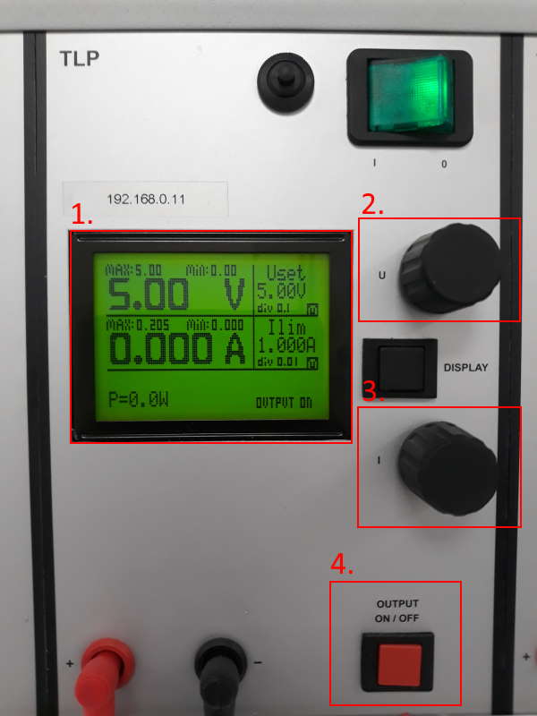
Equipment used on this task was a variable power supply.
- Display showing voltage, current and power. On the left side is output and on the right side maximum available value. Use the voltage (2.) and current (3.) rotating switches to change maximum value on the right side and then press Output (4.) to apply it
- Voltage controller
- Current controller
- Output button
Next we did some tests on different levels of voltage. Current was kept at the same same value, at 0.100A.
| Voltage | Current (Amps) | Power | Result | Image |
| 1.5 | 0 | 0 | Nothing | 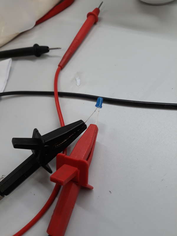 |
| 2.5 | 0 | 0 | Very slight glow | 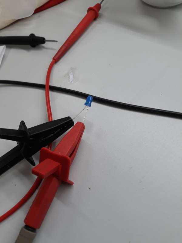 |
| 3.5 | 0.029 | 0.1 | Bright glow | 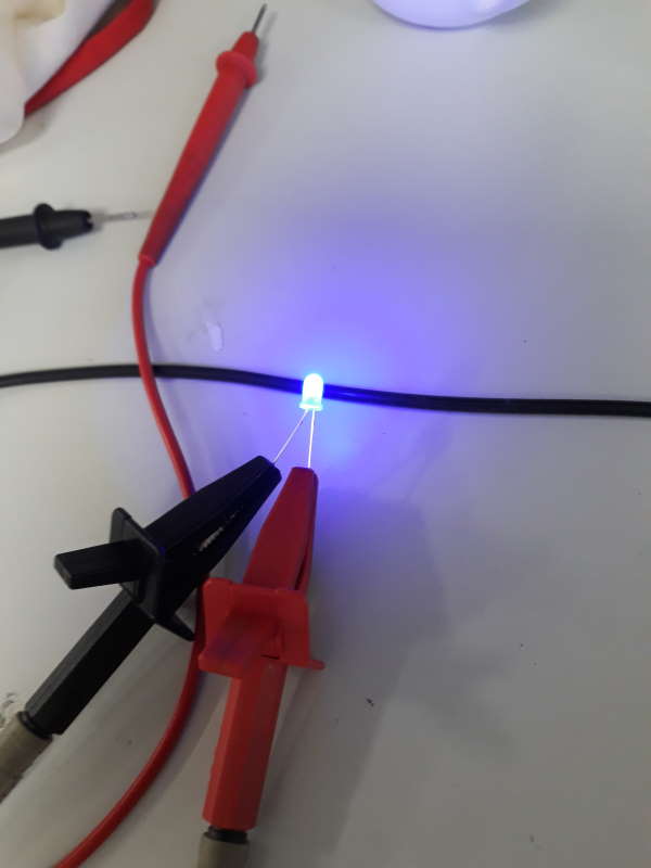 |
| 5 | 0.081-83 | 0.4 | Very bright glow | 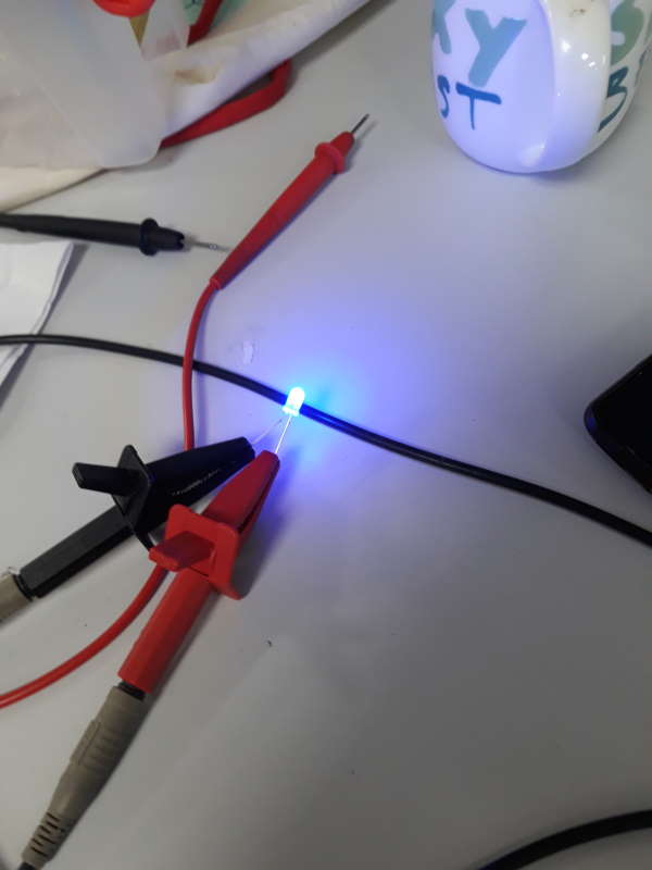 |
Next Jari noticed that, if we increase current too much the LED starts to blink instead of steady glow. When using 5V and 0.34 amps it started to blink. By only adding 0.02 amps (at 0.36) the led burnt.
This group assignment was a great experience since we could gradually see the difference between different settings.
Individual assignment
Lab is still closed due to covid-19. So this week I am going to test Tinkercad first time. My final project will use LCD display so that's going to be my focus. Most likely this will make it easier in future to start using one for real.
Tinkercad is a easy free-to-use collection of softwares to do 3D, electronics and coding.
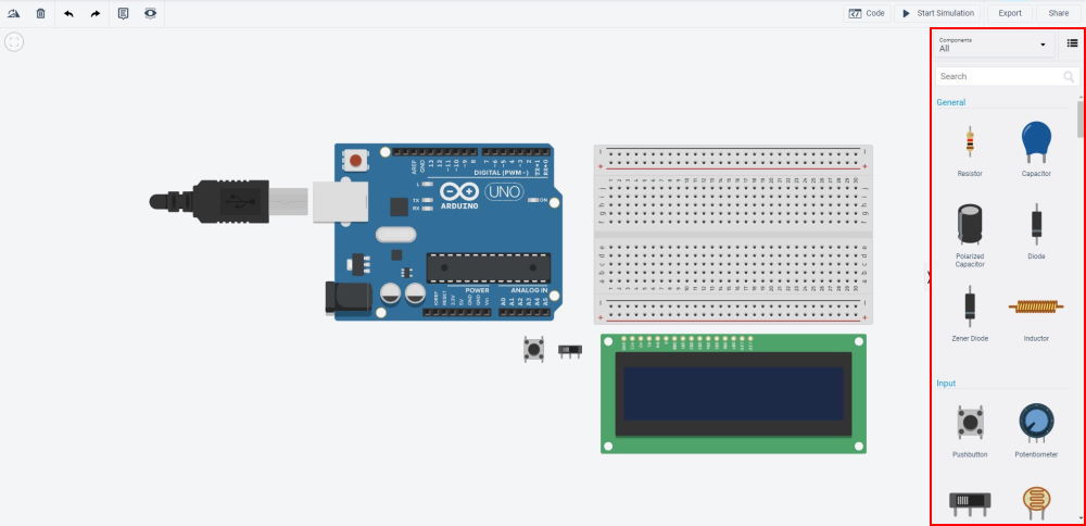
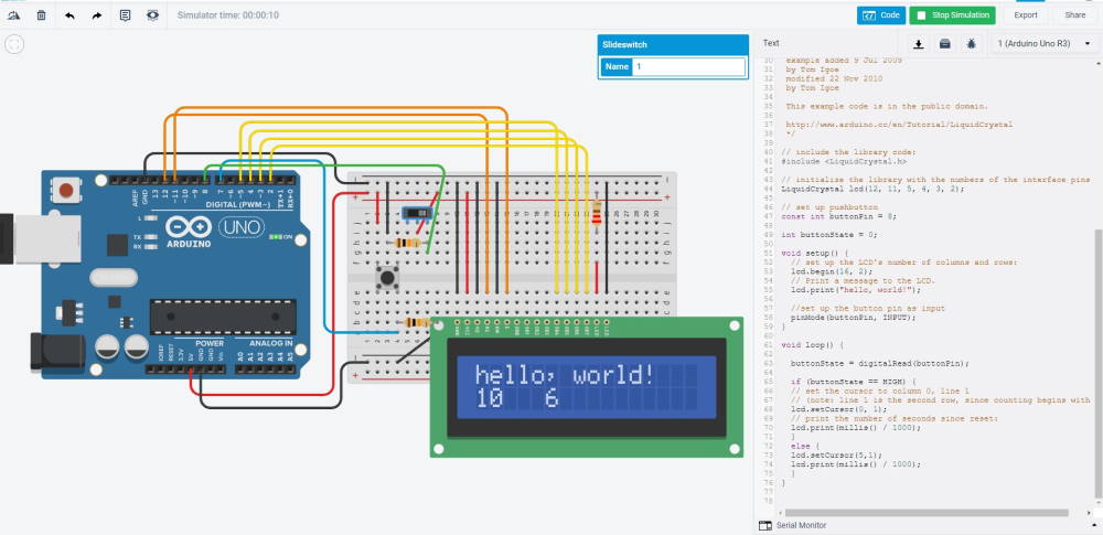
Starting with the a new circuit. With no experience on using LCD so I searched web and found nice example Arduino HelloWorld. This is not exactly what I want to, but it contains wiring for LCD and will add things on top of it what I want to use on final project. I started by picking following parts:
- Arduino Uno R3
- Breadboard Small
- LCD
- Pushbutton
- Slideswitch
I would have preferred Rotary encoder instead of button/switch to control LCD, but Tinkercad didn't have one.
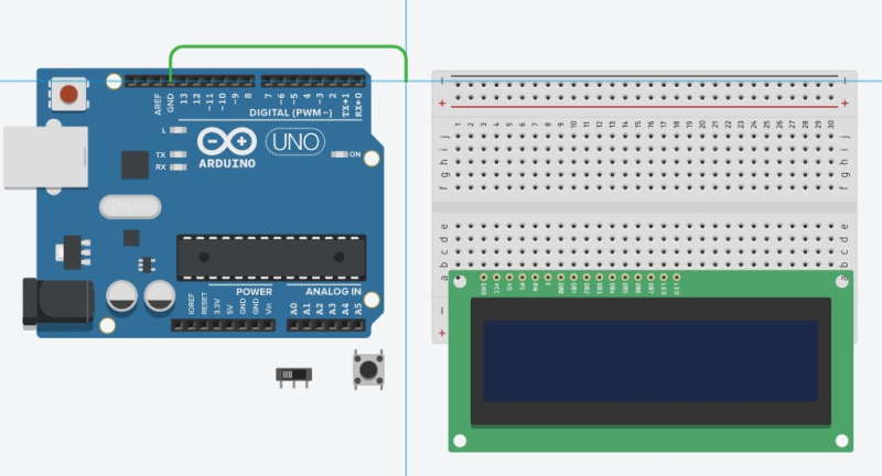
Wiring in Tinkercad is quick and easy. Just press on a pin and then click on the pin you want it to be contacted with. To make circuit easier to read wires can have a multiple points before attaching them from point a to b.
I began by adding 5v and ground to a breadboard. Because LCD was the main focus for this I started by adding wires for it next. First digital pins, gnd and 5v.
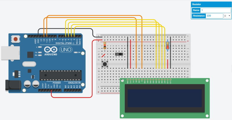
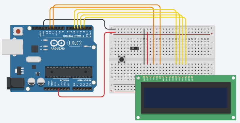
Next went for the LED anode and cathode pins. Cathode goes to GND and Anode to power through 220 ohm resistor.
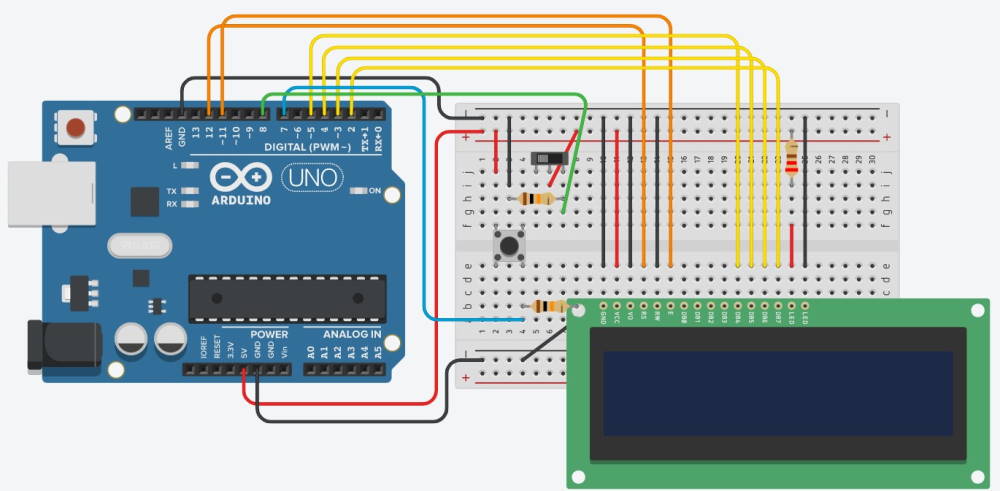
Here is the final circuit. Added voltage, ground and 10k ohm resistor for both slidswitch and button. For these used digital pins 7 and 8.
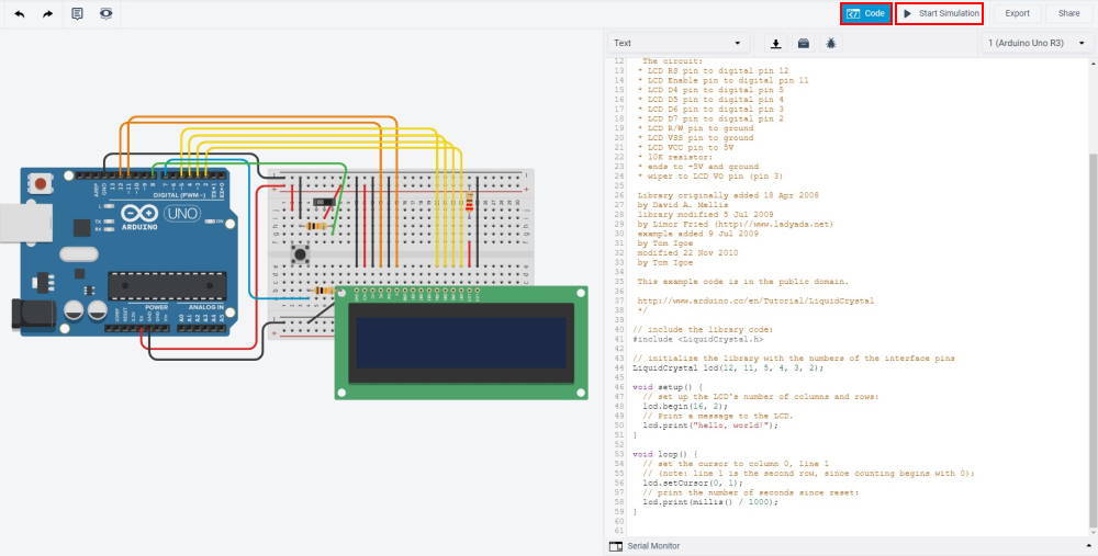
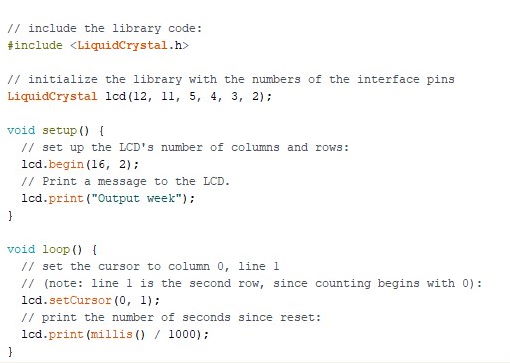
And finally to interesting part which is coding. To begin to understand basics of the LCD I tested the default code with HelloWorld and tuned it little bit at first.
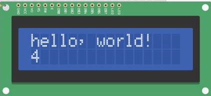
This is the print from original HelloWorld code. This one is only printing "Hello, world!" on column and line 0. And prints +1 in every 1000 milliseconds on column 0 and line 1.
Next I added some code for buttons to test how it is possible control the LCD with buttons. I set a simple if-statement to change output on line 1 if button is pressed. When button is pressed it would print the number at column 0 line 1 and if not it would print it on column 5 line 1.
Testing LCD display
Our lab has been open for few people at a time. Because of this I was able to get LCD display to test for the final project. Model we have is Lumex - LCM S01602DTR/M. It is 16x2 character LCD module.
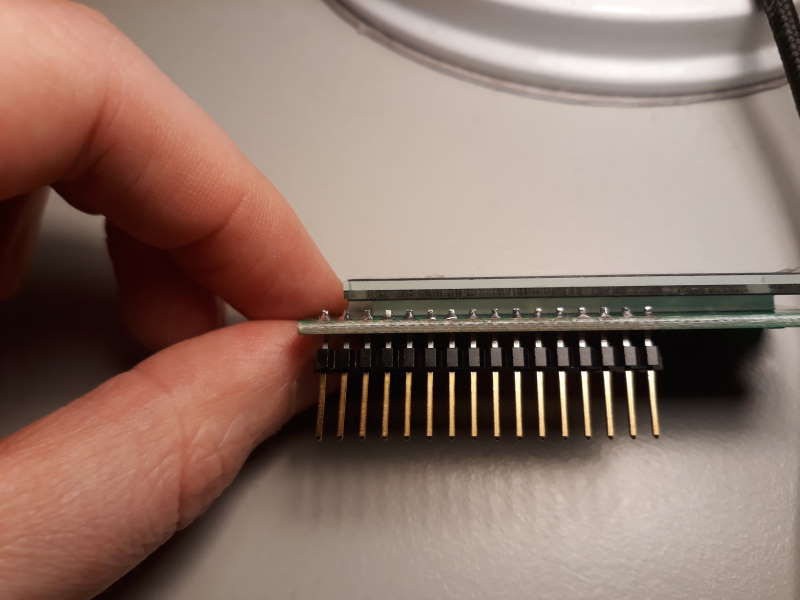
First I took 16-pins of FTDI-header and soldered it carefully im the slots. With this it is easier to work with.
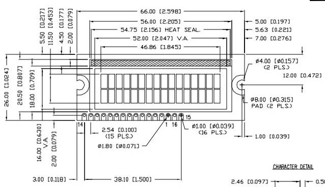
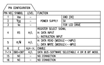
Here are dimensions of the module and pin layout from the datasheet. Pin layout is little strange since it is not sequental. Pins 15 and 16 are empty because this model doesn't have backlight.
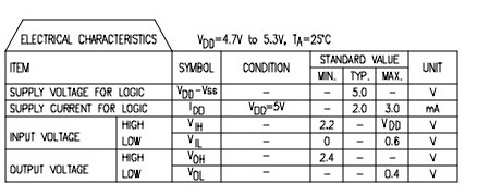
Here are electrical characteristics of the module. Supply voltage is 5V and Supply current is 2-3mA.
This is the Arduino LCD example. This is technically pretty much same as above done with tinkercad, but I dont have buttons to work with this.
video showing the final result.
Final project
I used LCD display on my final project and made a board for it. With research done on this week it was easy to use it on the final project. Documentation for this can be found from my final project page.