10. Input devices
This week I used The Arduino uno to program a light dependent resistor and control 4 LEDs depending on the Light conditions .
Implementation
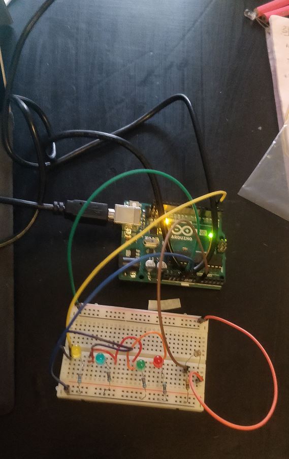
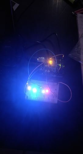
- For this assignment I used 4 LEDs along with 4x560 ohm current limiting resistors, a light dependent resistor with a 1k ohm resistor. The setup is as shown in the image. I connected all LEDS to common Arduino pin 2 and the LDR was connected to the Analog pin A0.

Connectionsetup
- After connecting everything I used the USB cable to connect the Arduino board to the PC. I opened the Arduino IDE and set all settings as shown in the tool setings below.
Toolsettings
-
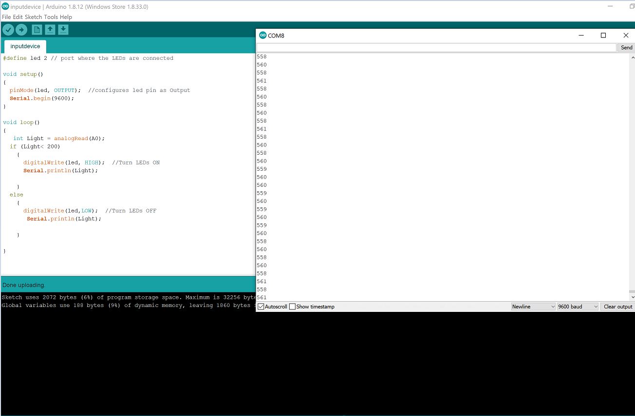
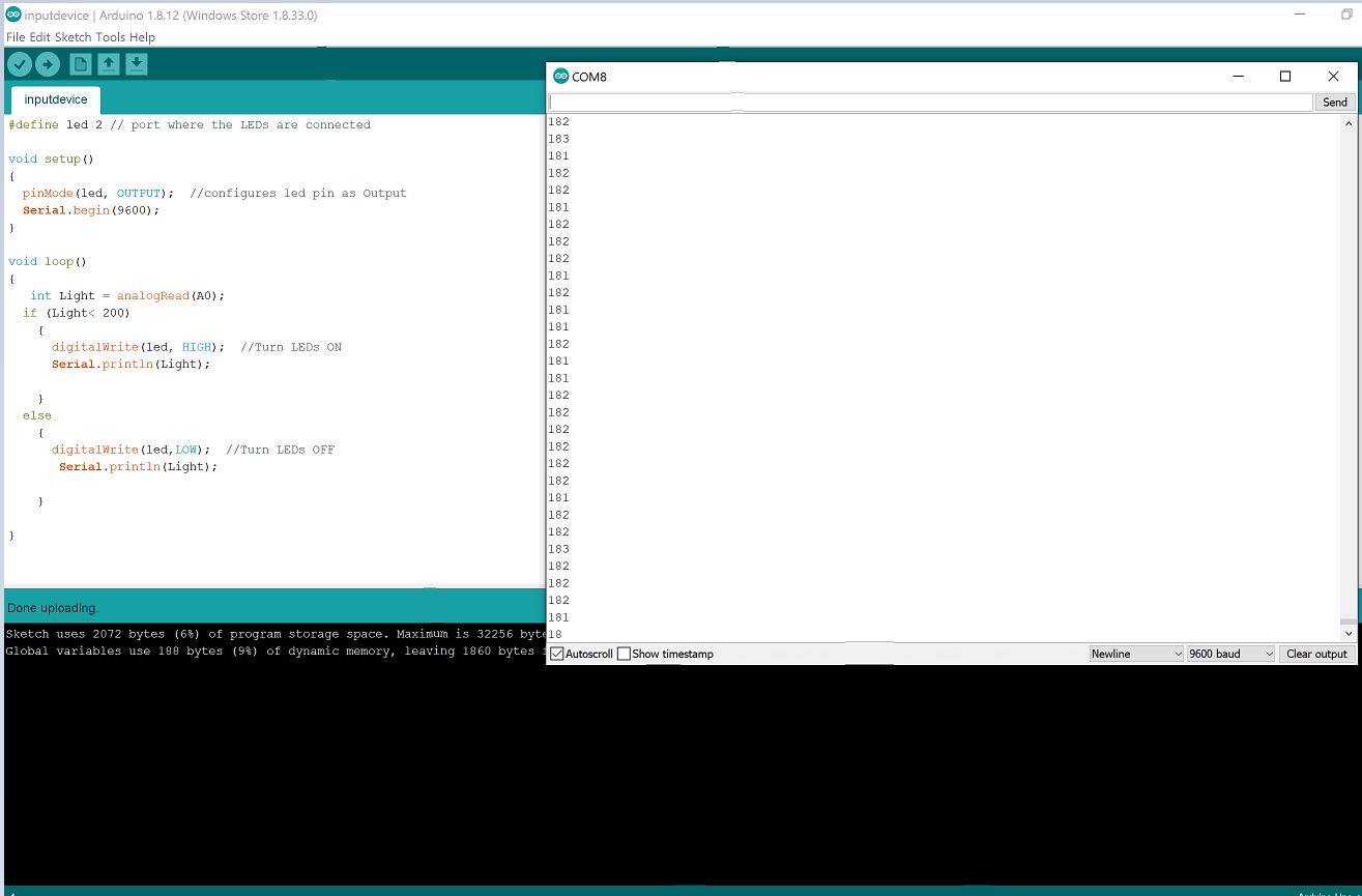
The program for the system was simple. I just declared pin 2 as an output port and and analog 0 A0 as input sensor port. After reading the sensor value I set the condition that if the light condition is less than 200 the LEDs should be turned ON or OFF otherwise. I also made use of the serial port to print the sensor values and analyse the lighting conditions that make the LEDs turn ON. The results are as shown below.
-
The ATtiny 412 has a 10 bit ADC therefore it can map any analog voltages to (2^10)-1=1024 values therefore since the value going to the ADC is represented by values from 0-1023 depending on the brightness.
Sensor values for Bright environment
LEDs Turn OFF when it’s Bright
Sensor values for Dark environment
LEDs Turn ON when it’s Dark
Final project
- In my Final project I designed and manufactured my own board and used the DHT11 sensor as input device, to record and display humidity and temperature values on an LCD and a smartphone, the documentation can be found here.
Group Work
For the Group assignment we used Fritzing with an LED as input device in order to test analog levels and digital levels. The documentation Can be found here