12. Output devices
This week I worked I experimented output devices and how to program them using PWM( Pulse Width Modulation)
Implementation
-
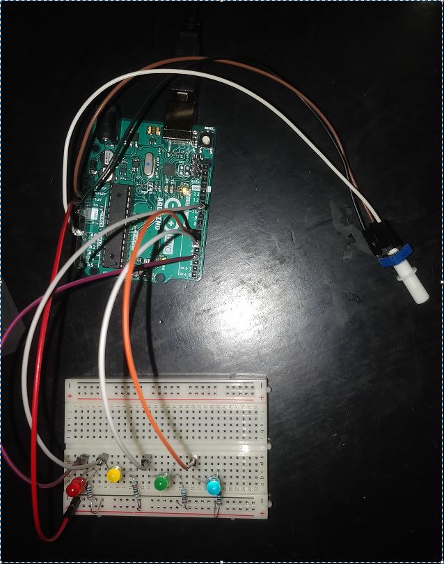
In this design I wanted to vary the Brightness of an LED using a potentiometer through PWM( Pulse Width Modulation). I used 4 different color LEDs 4x560 current limiting resistors and a 10K potentiometer. The goal is to turn the potentiometer knob and change brigthness of LEDS.
-
The image below shows the hardware setup.The 4 Leds are connected to 4 PWM output pins. The potentiometer’s 3 pins are connected as follows: The two front pins are connected one to a 5V output pin and the other to ground, the remaining pin at the back is connected to Analog input Ao.
 Hardware setup
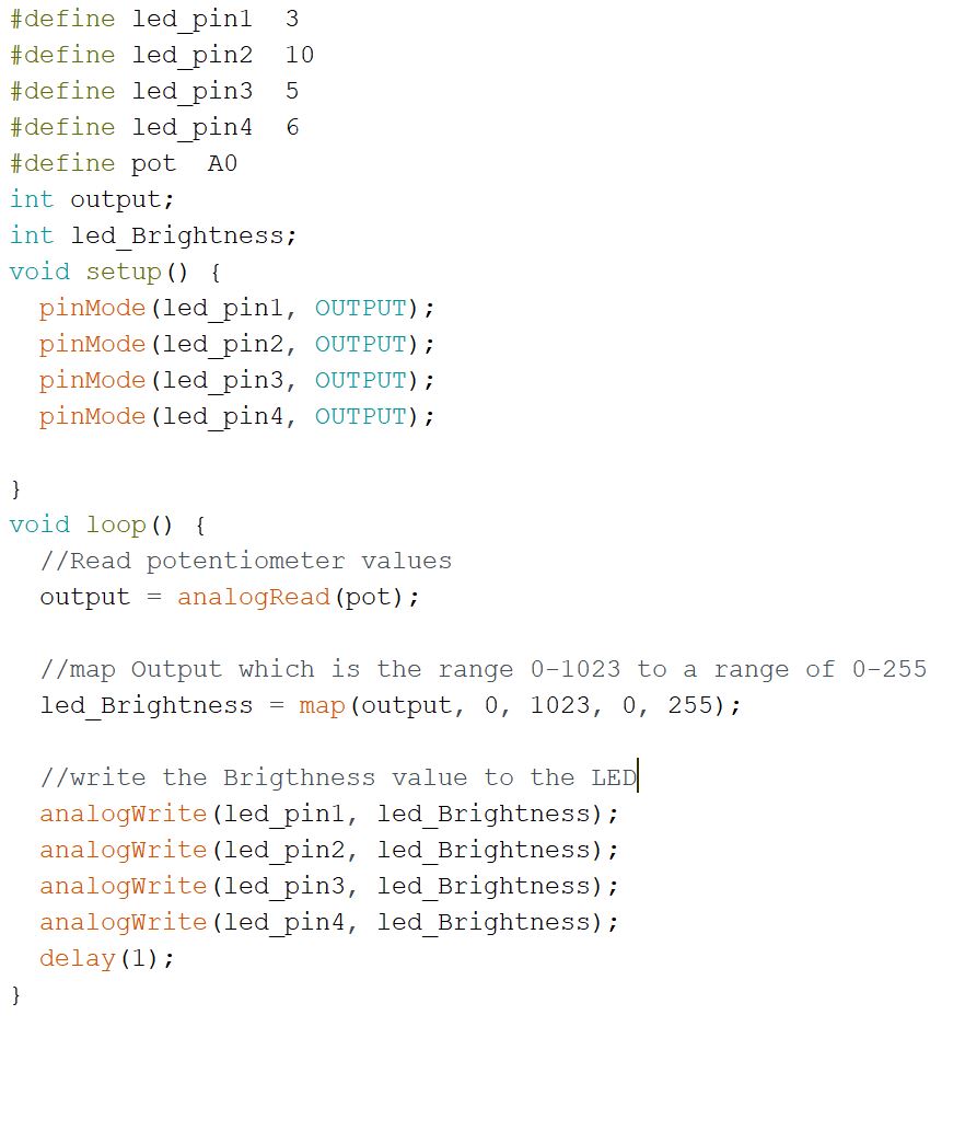
- To write the code I first declared 4 PWM pins and the analog pin. I then declared two variables one called output to hold values measured from the potentiometer using the analog and the other is Led_brightness the duty cycle of the PWM.
-
The potentiometer is connected to 5v input meaning that with each variation the volatage is reduced from 5 to 0 and hence these variations are sent as duty cycle values to the LEDs and change the brightness accordingly.
-
The potentiometer values are read through an analog pin and the Arduino uses a 10 bit ADC, therefore the values are in the range from 0-1023 but the Duty cycle of the PWM is from 0 to 255 therefore a map() functon is used to map the values from the potentiometer to a 0-255 scale. Then used the analogWrite() to write the Duty cycle values to the LEDs and vary the brightness
 Program
 -
The output observed is as shown below
Output
Final project
- In my final project I designed and manufactured my own board and used an LCD as output device in order to display humidity and temperature values recorded by the DHT11 sensor. Documentation can be found here
Group Work
- In the Group assignment we measured power consumption of an LED. detailed work can be found here