Week 16 :Machine Design - Vidya CNC PLOTTER
The group assignment of this week is to actuate and automate our machine and to document the group project and individual contributions.
Our Machine
Choice of machine
The first thing we tackled was to make the decision about which machine it was that we want to develop, with the resources available in the lab. We checked out the machines developed by previous students and also explored other possibilities, with this, we made a list of possible machines to develop.
In India all preschoolers start learning alphabets by writing on the sand. The teacher would write on the sand and the students would repeat it. But due to COVID-19, as children are at home learning from the television sets this was not possible. We wanted to make a machine that can substitute the teacher and the kids can learn the same way from home.
Nanditha found these videos on YouTube and we were inspired by them
And this viedo about Sisyphus table, a meditative kinetic sculpture that doubles as a side table or coffee table.
But on doing further research we realised it was not possible to get the required components like smooth sand, magnetic ball etc that is required to make this due to the COVID-19 restrictions at place.
When we bounced off this idea, Jogin told us to check out Core XY. This gave us the idea to come up with a machine that draws on paper rather than sand and we decided to use Core XY as our design reference.
“Vidya”-The name
We needed a name for our machine and since it is connected with education we decided to name it “Vidya”, which means learning in the local language, malayalam.
Specification
| Plotting area: 40 x 30 cm |
| XY moving precision: Not specified |
| Machine size : 60 x 60 x 10cm |
| Supported instruments: All types of pens, chalk, stick to draw on sand, large markers |
| Supported file format: GCode |
| Open source? Yes |
| Cost: Rs 2000/- |
What it does?
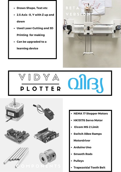
Vidya is a pen plotter or an XY plotter, It is a computer-controlled machine that draws graphics or text with precision over any media like paper, wood, plastic, cardboard or any flat sheet material. An image can be created by a pen of any size, which is raised, lowered, and moved over the printing media to draw. Its sole function is to guide a pen (or other implement mounted in the pen holder) along the set of vector lines, curves, and paths that you ask it to follow. Everything that the machine is ultimately capable of, such as drawing graphics, writing text, or signing documents, are expressions of this basic function. It is capable of drawing essentially anything that can be composed from a set of lines. In practice, this is much like using a traditional printer, except that you need to take care that your documents are made of paths, rather than pixels. This means that Vidya is a vector graphics device, rather than a raster graphics one. Vidya can recreate the appearance of hand drawing, and can consistently create high-quality prints. By attaching a the plain side of the pen and filling sand underneath Vidya instaed of flat sheet we can recreate the experience of a teacher writing on sand as well.
How does it work?
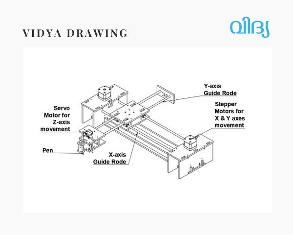
The way Vidya plotter works is similar to a 3D printer in that the movement of both is precisely controlled using XY coordinates. However, instead of the Z-axis that controls the up-and-down movement of a 3D printer, Vidya uses a precise servo motor to simply raise and lower the pen.
For XY movement, Vidya has two precision stepper motors in its base. Together, they drive a single looped belt that moves the carriage around in the XY plane. The high-performance linear stages feature custom-designed wheels that roll smoothly on custom aluminum extrusions, specially designed for high stiffness and light weight.
Upon giving the command of Pen Up (500, 500), the pen will move to the coordinate X=500, Y=500 without drawing anything, and if by giving the command of Pen Down (1200, 600), the pen will move to the coordinate X=1200, Y=600 while drawing a line.
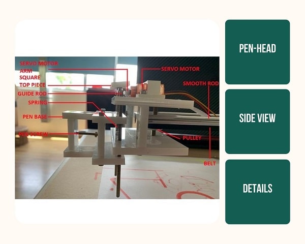
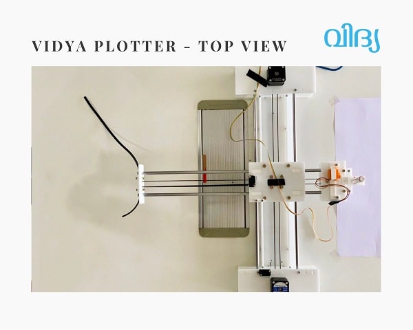
Vidya has an extendable drawing head, which can extend beyond the body, making it possible to work on flat objects bigger than the machine itself.
The header is attached to the metal rod arm and the belt. This arm moves left and right creating the movement along the Y axis.
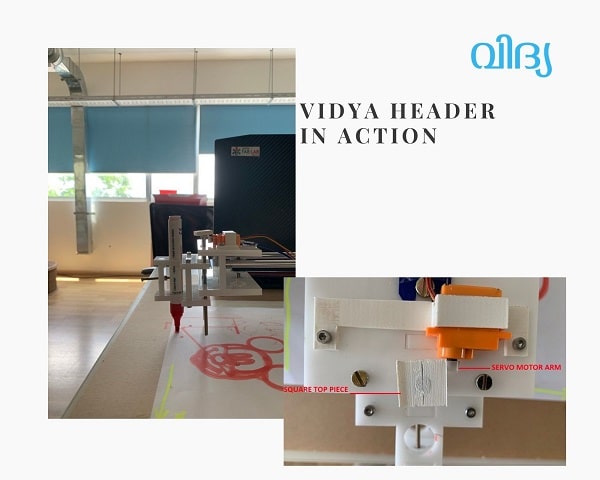
On that header the servo motor (Z axis) and the pen base is attached. Two guide rods on either side and a tension spring on a guide rod in the middle connects the pen base to the header. One part of the spring is grounded to the header and the other part is connected to a ‘Square top piece’ kept right above the servo motor.
Servo motor Movement(z-axis):
Position 1-When the servo motor raises its arm, the ‘Square top piece’ moves up, creating tension in the spring and extending it. This makes the entire pen base with the pen to move up causing the Z-axis movement.
Position 2-When the servo motor lowers its arm, the header moves down with it causing the spring to bring back the pen base and the header together again.
Materials Required:
| No | Item | Quantity |
| 1 | 6 mm Acrylic Sheet- 60 cm x 30 cm | 2 |
| 2 | NEMA 17 Stepper Motors | 2 |
| 3 | HL15178 Servo Motor | 1 |
| 4 | Elcom MS-2 Limit Switch | 2 |
| 5 | Xbee Ramps Motor Driver | 1 |
| 6 | Arduino Uno | 1 |
| 7 | Smooth Rod L-20cm , 8mm dia | 4 |
| 8 | Pulleys | 7 |
| 9 | Trapezoidal Tooth Timing Belt | 4 mtr |
Tools Used:
| No | Item |
| 1 | Autodesk Fusion 360 |
| 2 | Trotec Speedy 100 Laser Cutter |
| 3 | Ultimaker 2+ 3D Printer |
| 4 | Bosch GSB 180 Li Hand Drill |
| 5 | Arduino IDE |
| 6 | Inkscape |
| 7 | JTP Laser tool inkscape plugin |
| 8 | Universal GCode Sender |
Who did what?
Anooj's Documentation
Link to Anooj's Page - Anooj designed the X-axis and Y-axis housing
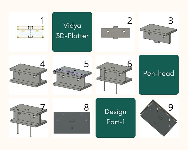
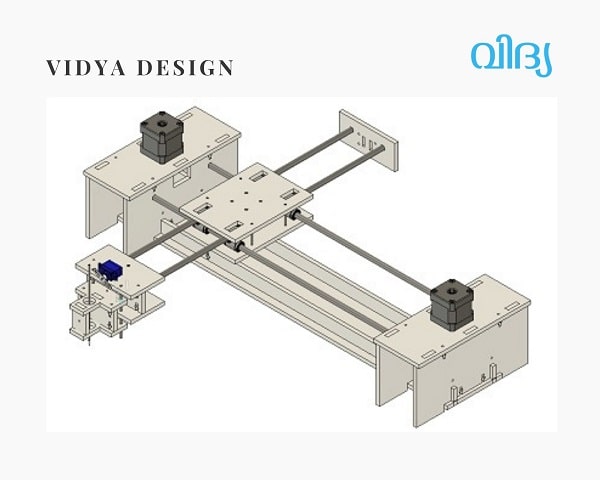
Designing
The designing part was done by 3 of us. We all used Fusion 360 for designing each individual part, so that we could combine it later to obtain the final model.
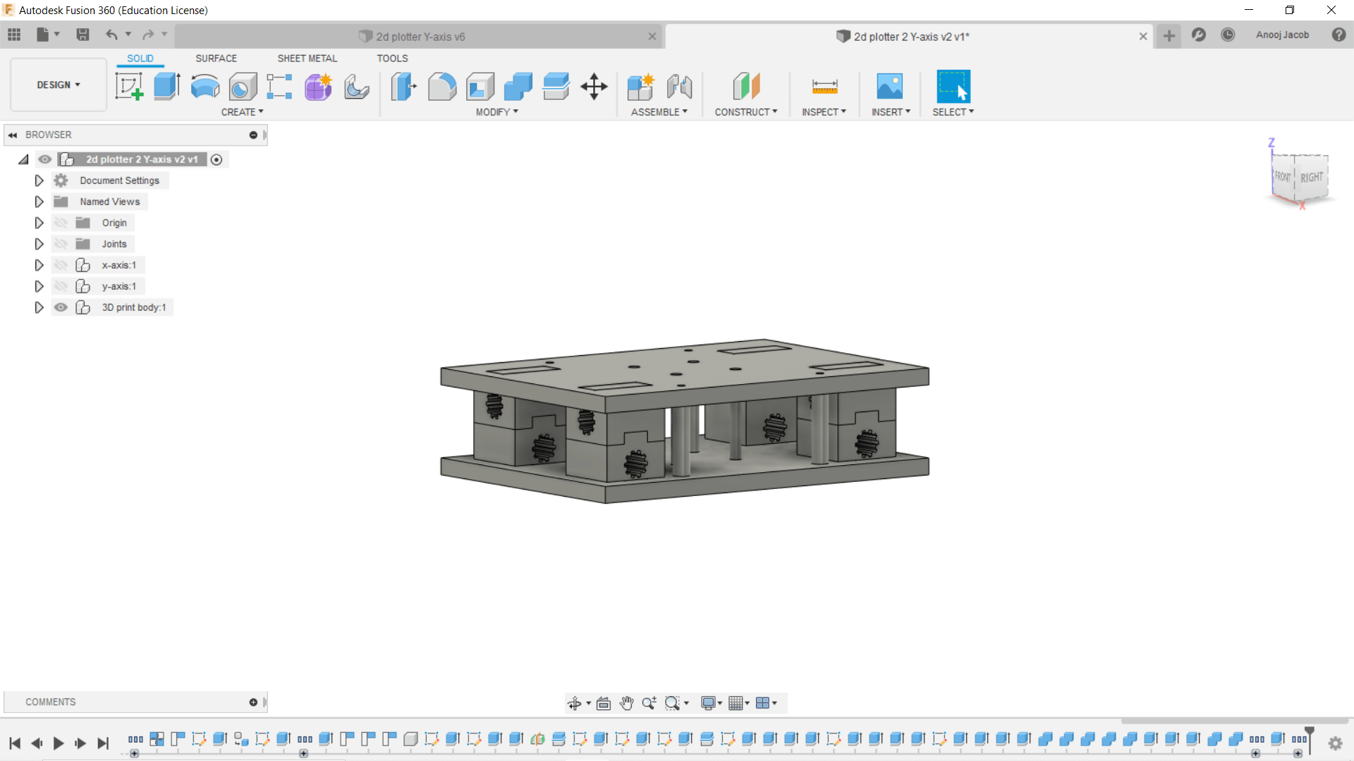
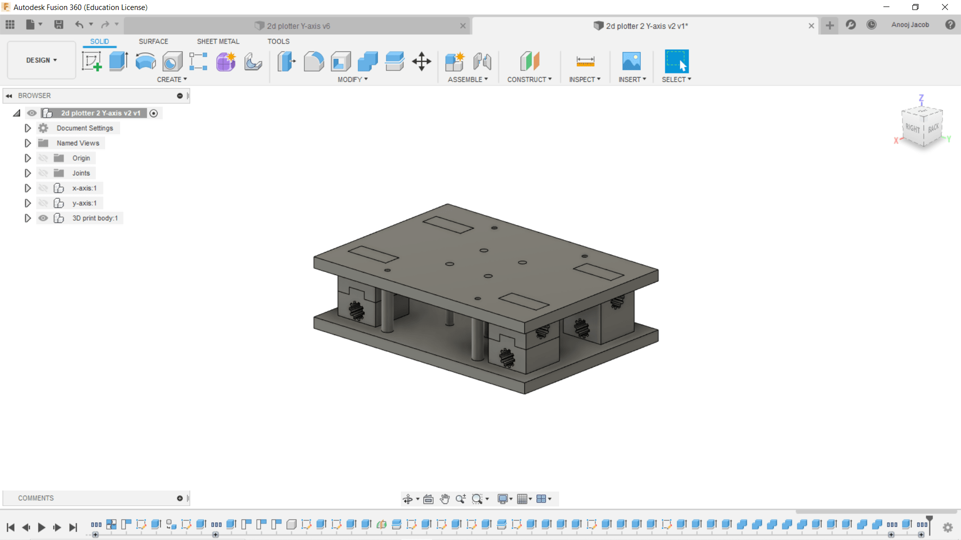
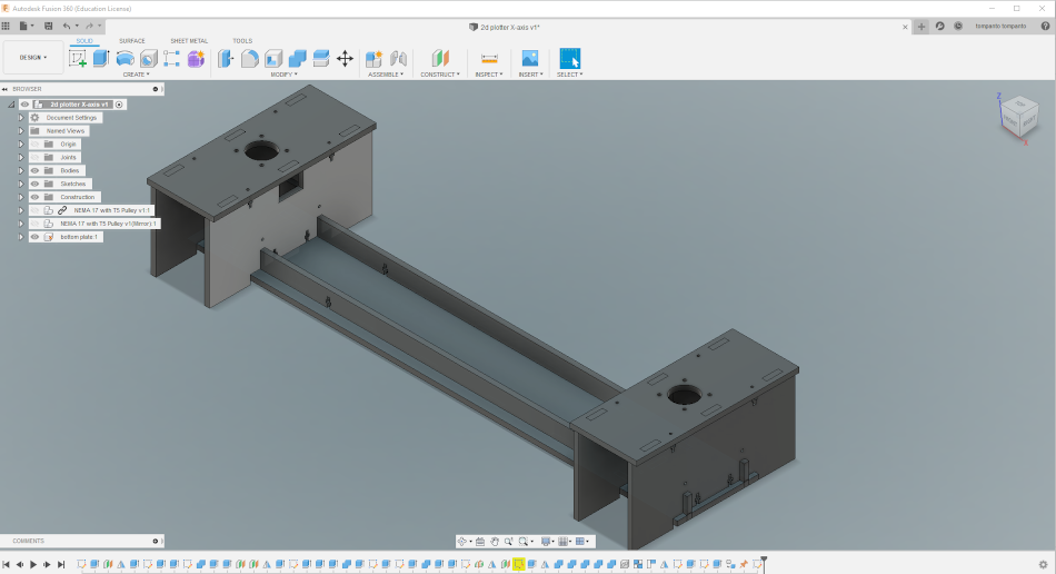
My contribution was to design the X-axis and Y-axis houseing. In our fablab inventory we had 8mm thick smooth rod and 6mm thick acrylic sheets, so keeping these values as the parameters I designed the houseing.
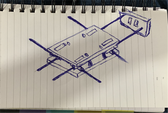
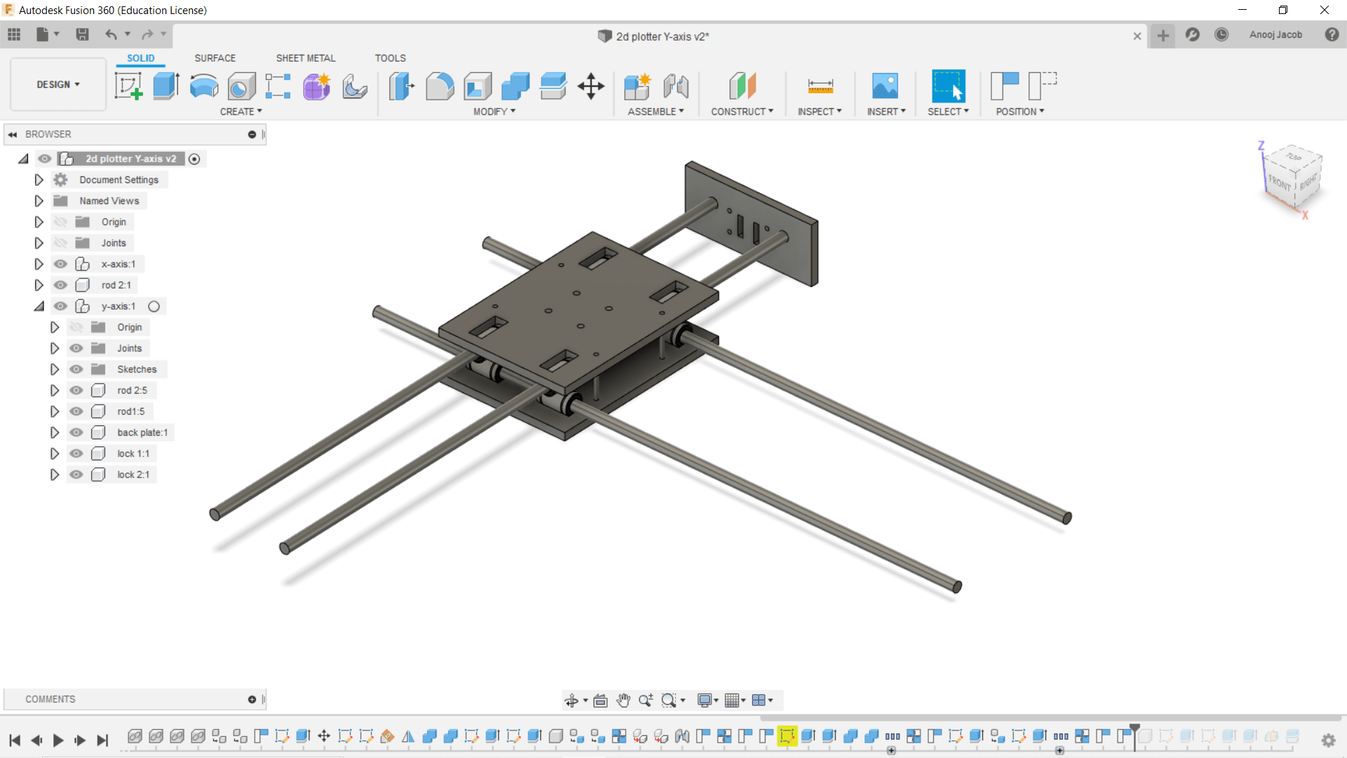
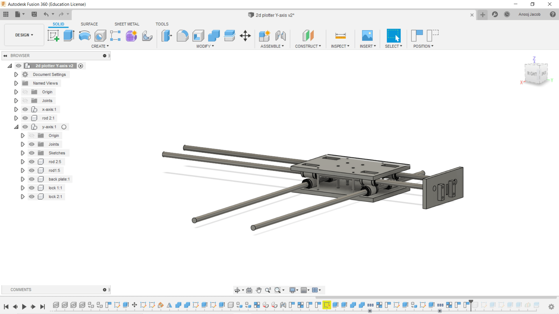
The design was in such a way that the top and bottom piece of the housing are acrylic sheets and linear bearing will partialy go inside the slots on the acrylic sheet and this assembly is tightened using 4 screws. The end plate on the Y-axis is where the belt will be locked.
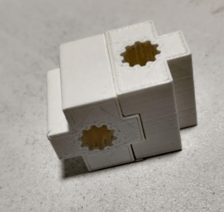
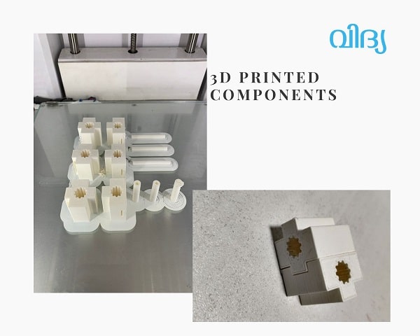
Unfortunately we couldn't get the linear bearing, so I had to change the design and 3D print a component that can freely move though the smooth rod. I then designed a bearing like component that can be attached to each other and to the acrylic sheet like a lego block.
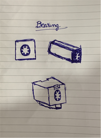
I then 3d printed to check the fit. luckily it worked well!!!!
Nanditha's Documentation
Link to Nanditha's Page - Nanditha designed the Pen Holder on Y-axis, designed the poster, created the video and documented this page
What I did Step-By-Step:
I did the design of the header on which the pen is kept. This header is attached to the metal rod arm and the belt. This arm moves left and right creating the movement along the Y axis.
On that header I attached the servo motor (Z axis) and the pen base. Two guide rods on either side and a tension spring on a guide rod in the middle connects the pen base to the header. One part of the spring is grounded to the header and the other part is connected to a ‘Square top piece’ kept right above the servo motor.
Servo motor Movement(z-axis):
Position 1-When the servo motor raises its arm, the ‘Square top piece’ moves up, creating tension in the spring and extending it. This makes the entire pen base with the pen to move up causing the Z-axis movement.
Position 2-When the servo motor lowers its arm, the header moves down with it causing the spring to bring back the pen base and the header together again.
I also made the poster and part of the video as I’m way more faster in these softwares. Tom helped me with poster and video by giving elements required for adding to it.
I also wrote the documentation.
Design
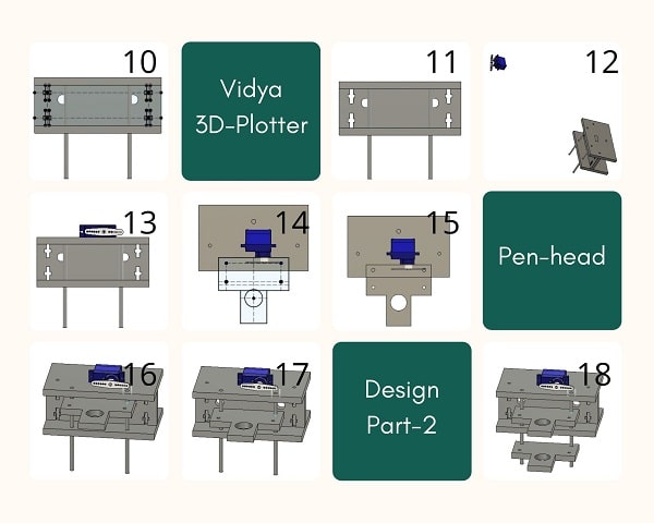
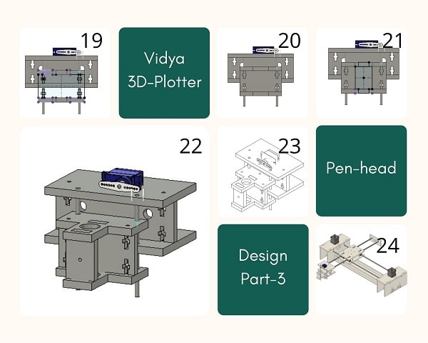
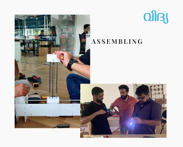
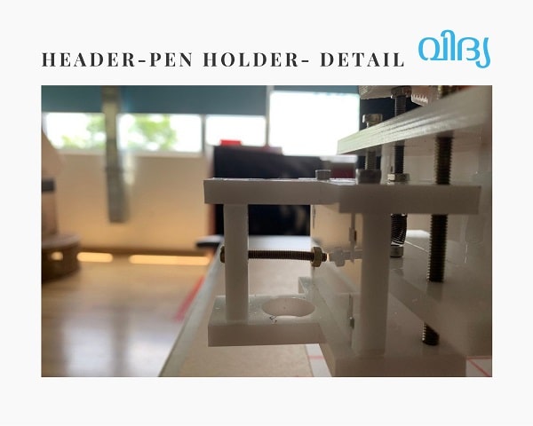
Assembly
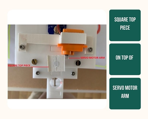
‘Square Top Piece’ that rests on top of the servo motor arm.
Pen is kept in the hole and screwed in. This mechanism allows any size pen to be kept in the hole.
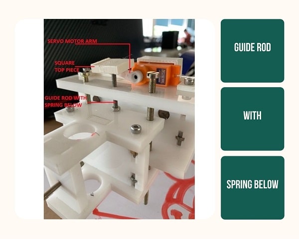
Guide rods that keep the pen base on to the header. The entire weight of the pen base is holded down to the screw on the guide rod. The pen base can freely move up and down on the guide rod.
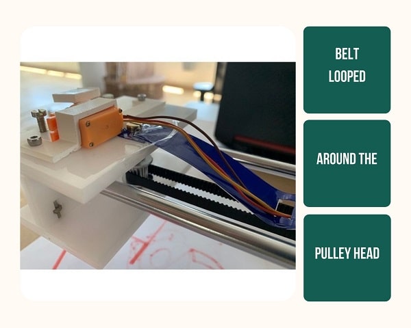
The belt is looped around the pulley kept on the backward facing side of the pen header between the two metal arm rods. When the pen has to move along the y axis, the stepper motors moves the belt causing the rods to jet out in the back which causes the pen header to move with it.
The two stepper motors move in two speeds causing the belt, that is looped along them and along the two arms, to move. It is the speed difference in these two stepper motors that creates the motion along the x-axis and y-axis.
Mistakes and Learnings
In the initial design, there was no spring. The servo arm raises the pen; when the arm goes down, gravity lowers the pen. It was since then that we created the better, more precise pen holder that uses the spring action to raise the pen base. This avoids the pen base from getting stuck.
Tom's Documentation
Link to Tom's page - Design the Y-axis and assist in poster creation.
Designing X axis arm of CNC plotter
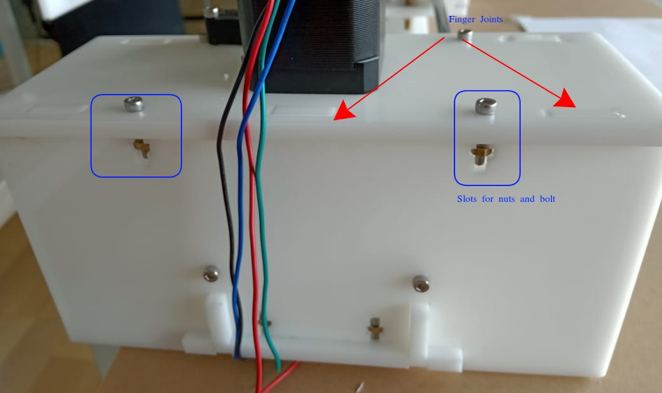
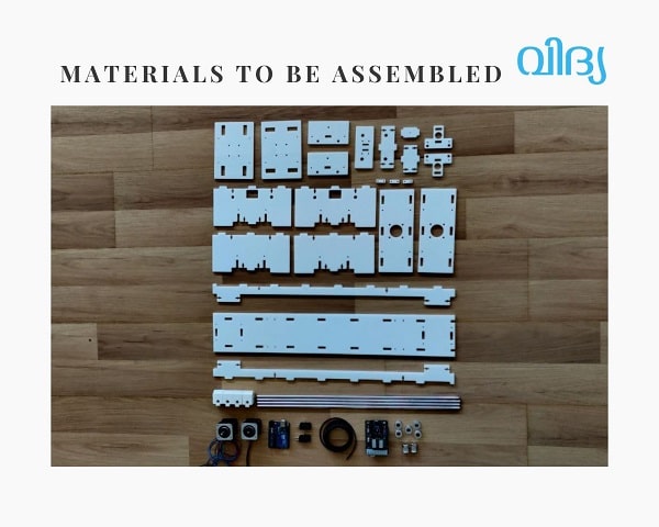
We did parametric designing in fusion 360. My design part consists of two housings for holding two NEMA 17 stepper motors and two 8 mm smooth rods. Components/parts are joined through finger joint mechanism . I also provided slots to accommodate nuts and bolts , this is also for joining parts and hopes it will give more rigidity to the machine. For giving holes for stepper motors I imported nema 17 design file to fusion 360 and did necessary extrusion- cut operation for accommodating motor's shaft from top side.
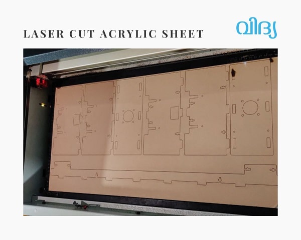
We used acrylic sheets for fabrication.After completing the design I shared the file with anooj and later we assembled all parts . We used laser cutting machine for making parts from acrylic sheets. And also used 3D printer for printing some critical components
3D Printing and Laser Cutting
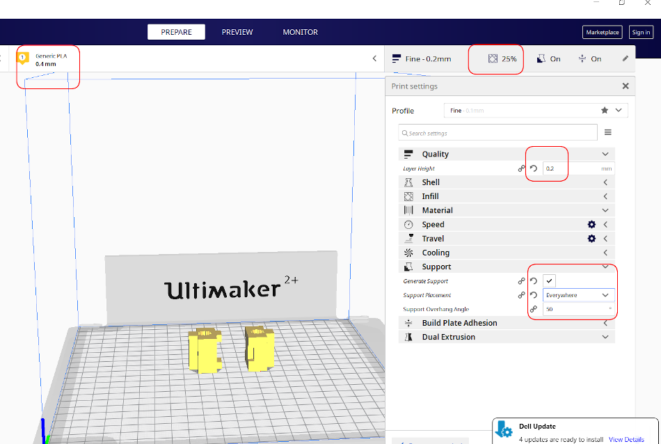
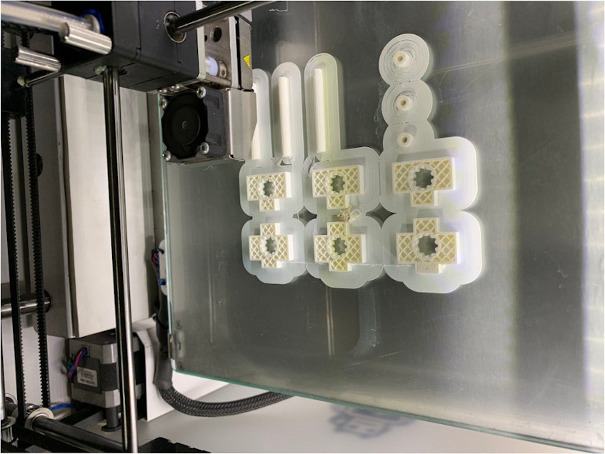
Linear Bearings at the junction of X axis and Y axis arm are designed by Anooj and I 3D printed the bearings.The hole dia of linear bearing is given as 8 mm (dia of smooth rod). After doing some post processing job on linear bearing, we were able to get a desirable fit Settings for 3d priner is shown below. Print settings are 0.4 mm nozzle, 0.2mm layer height etc.
3D printing in progress
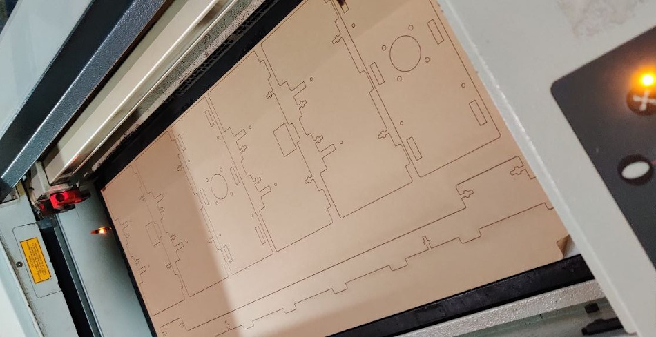
I used a 6 mm acrylic sheet to laser cut the main frame components.A test cutting was done for understanding the Fit and tolerance required for joints. Without giving kerf value we got desired fit for the joints.
Eldho's Documentation
Link to Eldho's Page- Electronics and movement
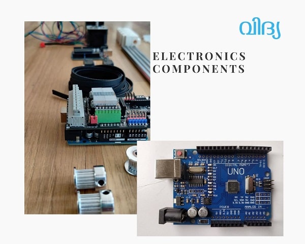
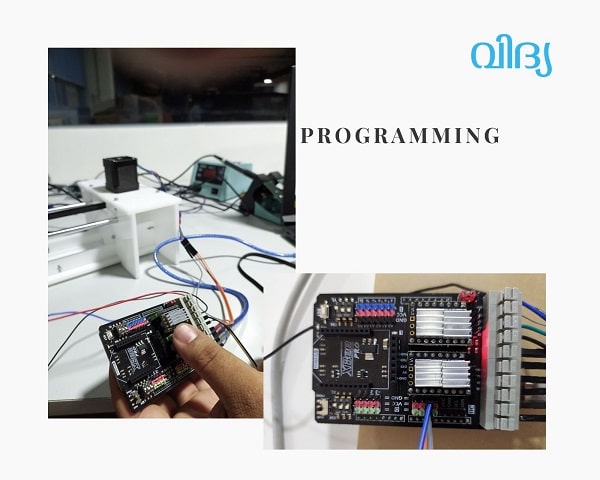
Arduino and motor shield
Arduino Uno is a microcontroller board based on the ATmega328P (datasheet). It has 14 digital input/output pins (of which 6 can be used as PWM outputs), 6 analog inputs, a 16 MHz ceramic resonator (CSTCE16M0V53-R0), a USB connection, a power jack, an ICSP header and a reset button. It contains everything needed to support the microcontroller; simply connect it to a computer with a USB cable or power it with a AC-to-DC adapter or battery to get started.
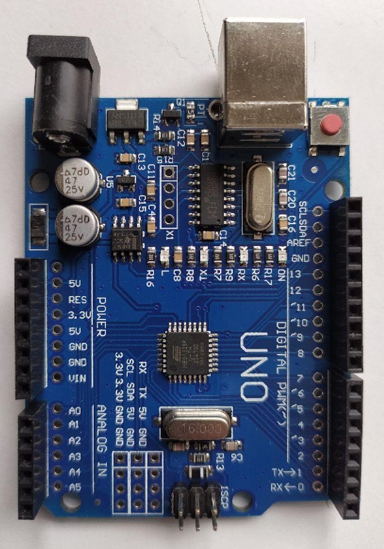
SO vidya works on a Arduino Uno platform. All the instructions for the movement of the machiene is fed into this board.
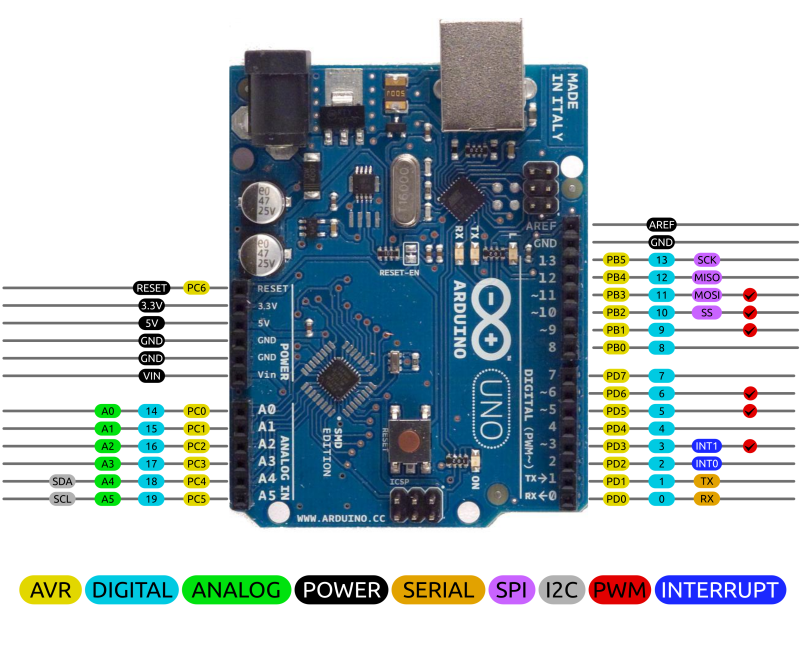
So its important to know the complete pin mapping of the Arduino board to place the step-motor shield.
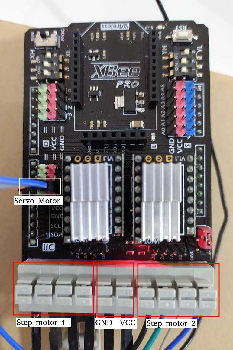
The Arduino Motor Shield allows you to easily control motor direction and speed using an Arduino. By allowing you to simply address Arduino pins, it makes it very simple to incorporate a motor into your project. It also allows you to be able to power a motor with a separate power supply of up to 12v.
Motor shield used here is Xbee pro which can be directly placed over the ardunio uno board and programmed for the desired movement.More information on the shield used can be found here .
GRBL FIRMWARE
After assembling the machine the next step is to set the movement of the machine, i need to assign a firmware for precise movement of the machine.
WHAT IS GRBL FIRMWARE?
The firmware is basically a preloaded set of codes and command which detects the input and outputs of the device. Now one device can only do work if its firmware can detect other commands. GRBL is an in-built software or firmware used in Arduino. Through this, one can use the Arduino easily. Now, this GRBL firmware can be installed in any version of the Arduino controller. For instance; Arduino UNO, Nano, Duemilanove, etc.
So, it is now understood what a GRBL is! Now the question is, how GRBL will be connected to the device? The simple answer is it uses the G-Code to control the hardware. So again, one question comes around. What is G-Code? So, G-code is a set of instructions through which one can design the code according to the necessity. Then they can port the instruction into the controller using the GRBL software. The most important point about the GRBL controller is it uses a simple USB port, where the other CNC controller uses the red or pink big pins to supply power as well as information. So, it is comparatively very handy. Because USB is very commonly available in the market, Arduino is not an exception to it. Additional information on CNC machienes can be obtained from this website.
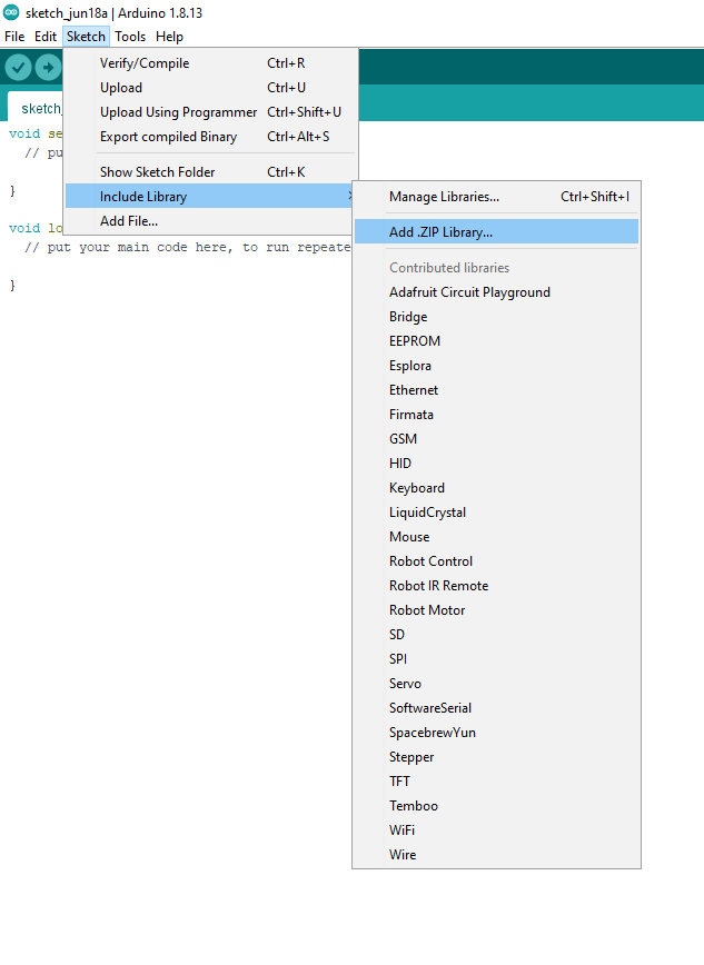
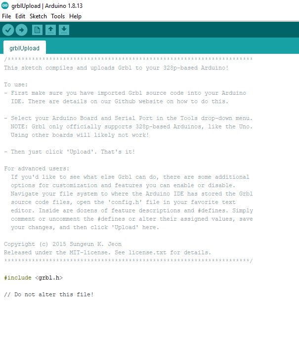
1) First step is downloading a firmware grbl. After reading a lot about differnt firmwares and after long search i downloaded a firmware . After the download, the file should be added in arduino as a library.Sketch => Include library => Add. Zip library- And add the downloaded library.
2)After this process we have to edit the pins in the library, for that
go to the arduino folder => libraries => grbl servo master => cpu map and select cpu map atmega328p.h.
The pin should be changed in the cpu.map file which are selected regions in the upload file as shown below.
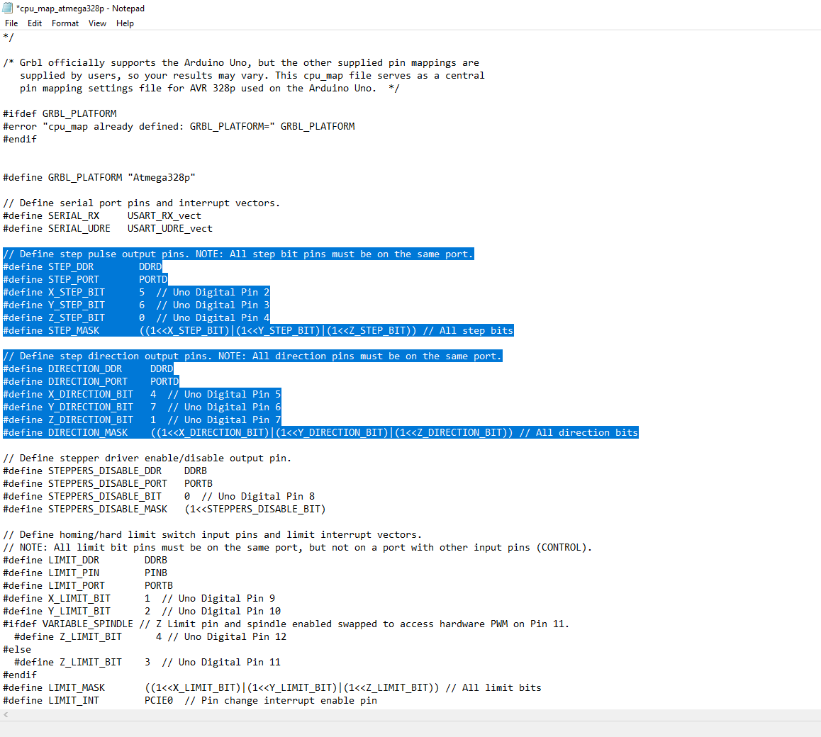

3) Next step is editing the pins in the selcted area.These pins are deicated pins to the various step motors used.
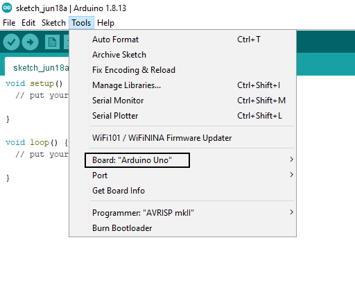
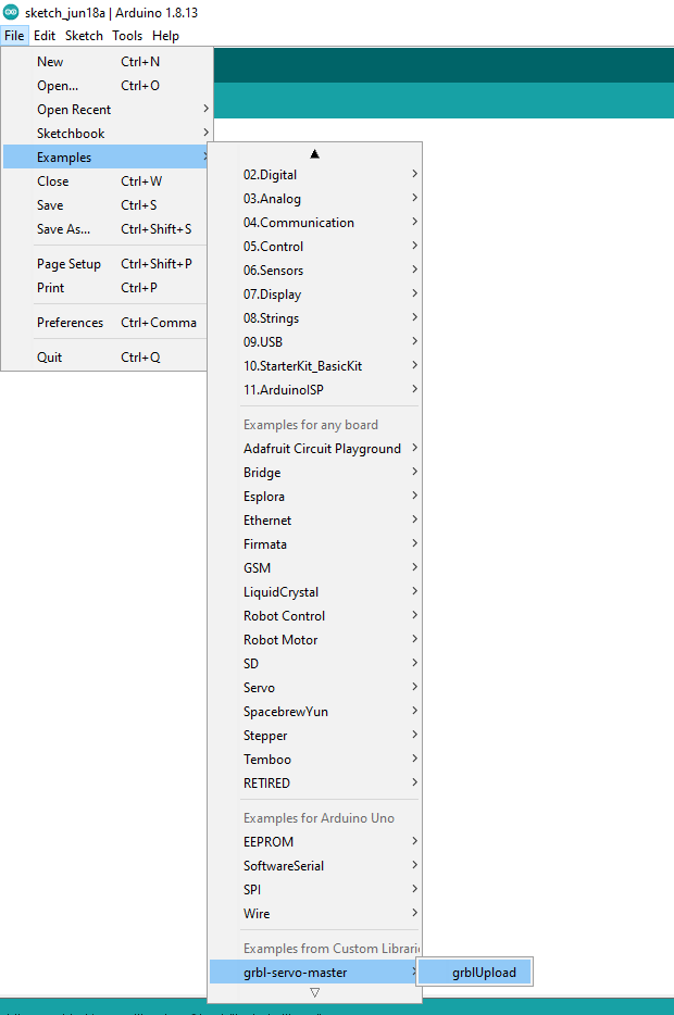
4) After assigning the pins open Arduino go to tools and change the board to ardunio uno as shown in the above pic. And then open examples => grbl servo master => grbupload as shown below. Once all this is done upload the program to arduino uno.
After grb-upload.
- Compile and upload
Grbl-coreXY-servoto your Arduino. - Connect your Arduino Uno to the computer.
- Make sure your board is set to the Arduino Uno in the
Tool => Board menuand the serial port is selected correctly inTool => Serial Port. - Click to Upload the program, and Grbl-coreXY-servo should compile and flash to your Arduino! (Flashing with a programmer also works by using the Upload Using Programmer menu command.)
Callibration
- The next main step is caliberating the machine since the movement of the machine needs to be quantified so that the program understands the distance moved by each axis.
- For that we have to calculate the distance covered by the belt when the step motor covers one 360 degree rotation.
- For nema17 step motor 1 revolution is 200 step
- since we used microstepping for smooth flow the step increases by 8 times and becomes 1600 step
- Next we need to know the distance covered for 1600 steps
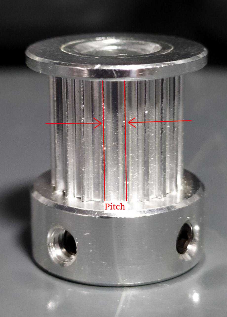
- For that pitch of the pully is measured and is 2 mm and is also confirmed from pulley datasheet.
- Numer of tooth in the pulley is 20. so distance covered is 20* 2 mm = 40 mm.
- So steps taken to cover 1 mm distance 1600/40
- So 40 step is taken to cover 1 mm distance
- This value can be used to caliberate the plotter.
Nibin's Documentation
Link to Nibin's Page- Programming and movement
Electronics and programming
In electronics and programming part our task was to program the Adruino UNO board and the DFrobot stepper motor shield board inorder for the stepper motors and servo to work,and to generate the gcode
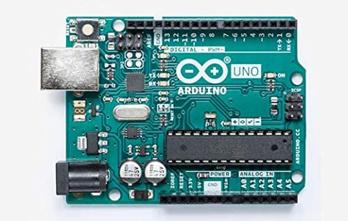
Arduino Uno Board
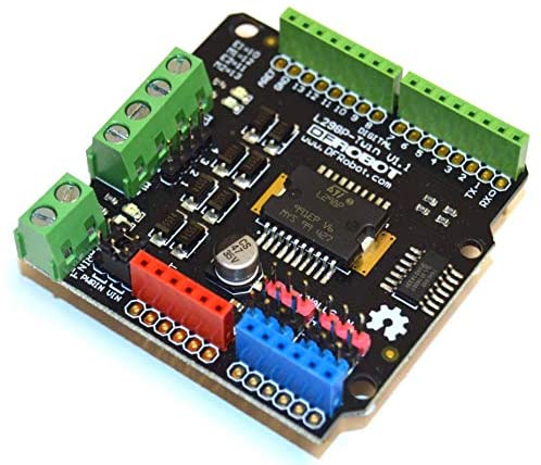
DFrobot stepper motor shield
Generating G code
There are many softwares for generating gcodes,and many gcode generating softwares are available online.I used the vector design software Inkscape for generating gcodes becase i was familiar with software.Inkscape has got inbuilt Gcode generating extension for the new version .
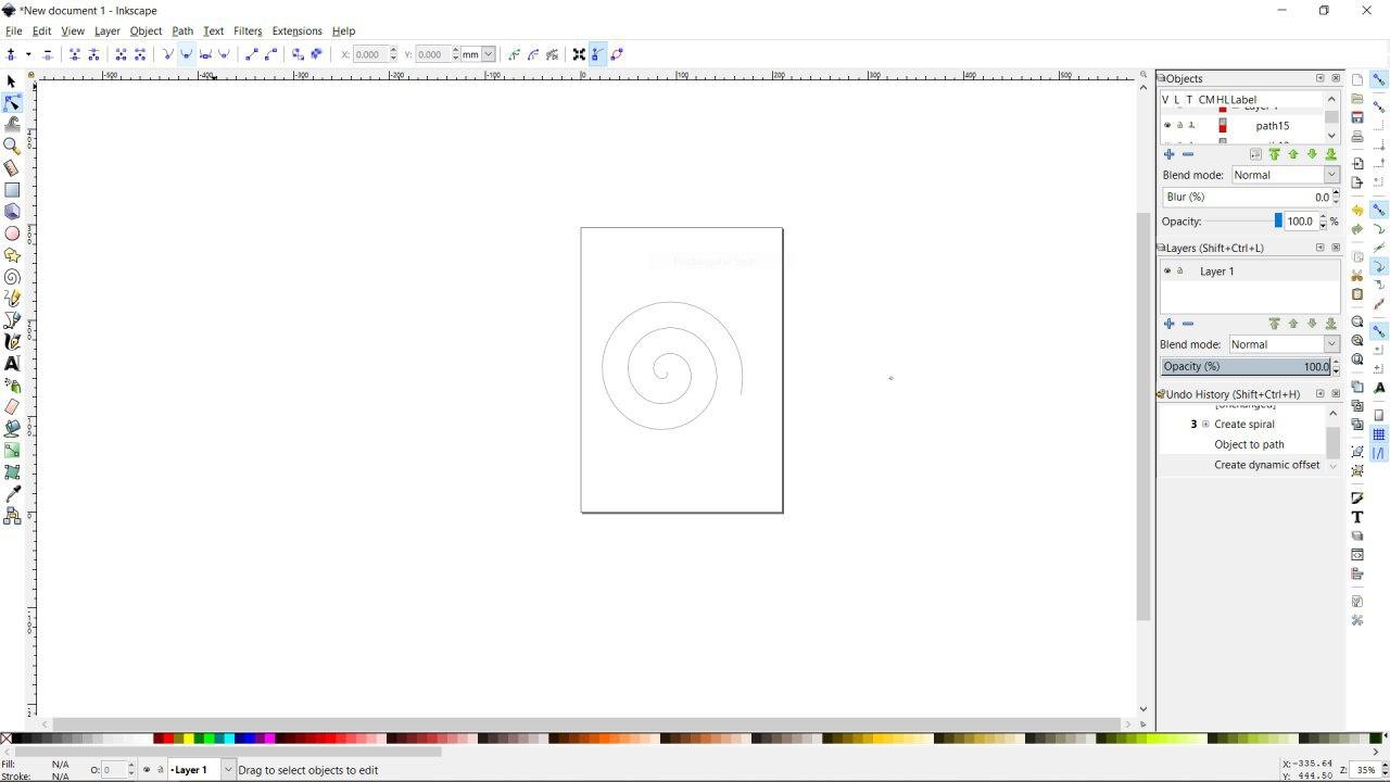
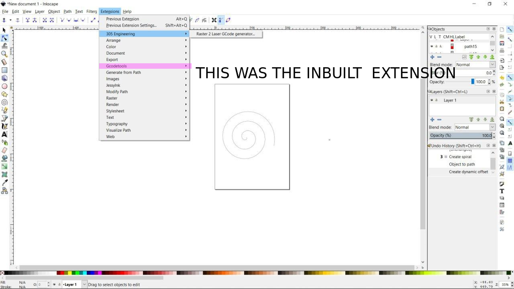
Luckly, for me it didnt work so i had to download anathor extension for generating gcode for inkscape.
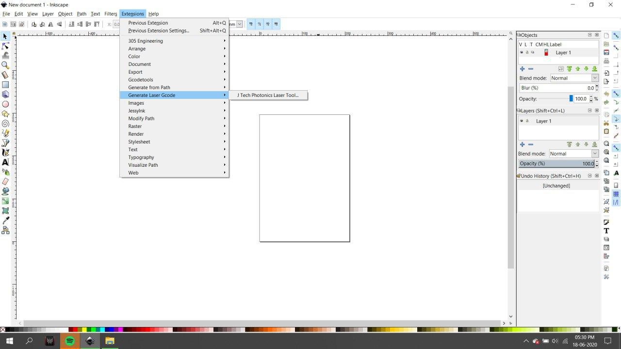
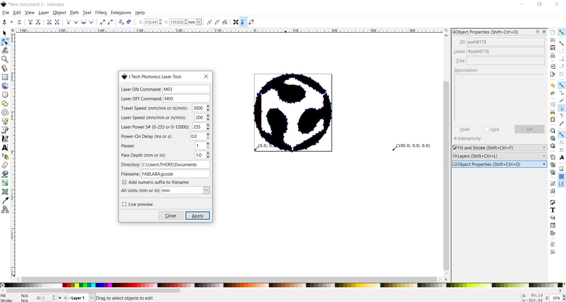
The extension i used is JTP Laser Tool Inkscape Plugin
[This Inkscape plugin will convert paths/drawing to G-Code for Vector Printing]
• Download the plugin from JTP Website
• Extract it using any good unzipping software.
• Put the contents of this .zip folder into the “inkscape\share\extensions” folder in installation directory.
• Once it is there it will show up under the “extensions” tab in Inkscape.
For processing gcode from Existing JPG/PNG Image in Inkscape
• Open Inkscape.
• Open the template you have downloaded in previous step according to your paper size.
• Click on File -> Import then select the JPG or PNG file from your drive and click open.
• Resize and position the image according to your page size.
• Image must be inside the boundaries of the page or G-code will not be generated properly.
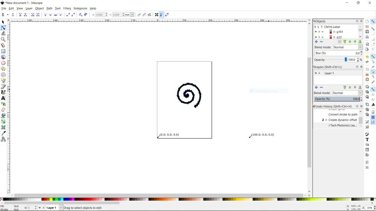
• Right Click on the image and select Trace Bitmap.
• Select any of the Three Option [ Experiment and You will know the working] Brightness Cutoff, Edge Detection, Colour Quantization.
• Change the threshold according to the details you want in the drawing.
• Click on Update.
• Click OK and close the window.
• The Vector Bitmap will be overlapping the original picture.
• Drag out the original picture and delete it. You are ready to generate G-code.
• Now See G-code Generation Step.
Processing from Custom Drawing in Inkscape
• Open Inkscape.
• Open the template you have downloaded in previous step according to your paper size.
• Start drawing or writing text inside the work area.
• Select all the objects by Ctrl+A shortcut.
• Group then together by Object -> Group from menu or by Ctrl+G shortcut.
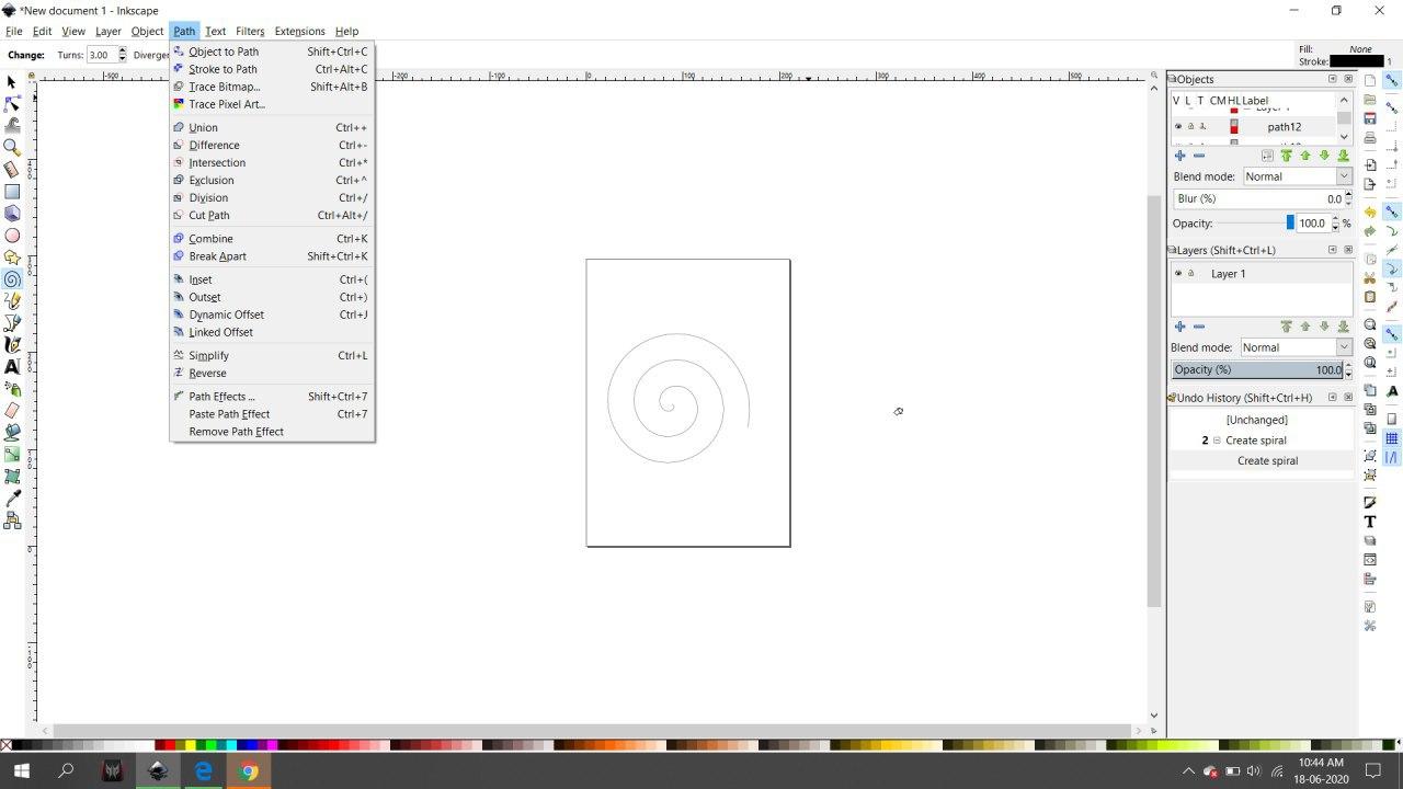
• Then you have to convert object to path from menu Path -> Object To Path or by shortcut Shift+Ctrl+C. [ Important Step]
• Now See G-code Generation Step.
Gcode Sender
The next task is to send the generated Gcode to machine so that it draws the design.For this i used the platform Universal Gcode Sender.
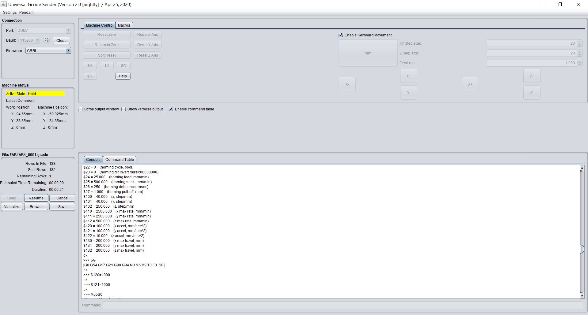
The Universal Gcode Sender will send G-Codes from laptop to Arduino UNO via USB Serial Port
• Download and install the version of Java listed on the download page according to your OS and system configuration. Requires Java 8.
• Download UGS Platform UGS Download
• Extract it using any good unzipping software.
• In the extracted folders locate bin in the ugsplatform directory.
• On Windows run ugsplatform.exe or ugsplatform64.exe, on Linux or Mac OSX run ugsplatform.
• No need of any installation or build.
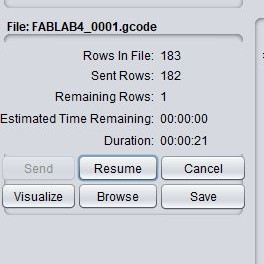
After setting up the Universal gcode sender we have to upload the previosly gcode file to the platform and send to the machine.
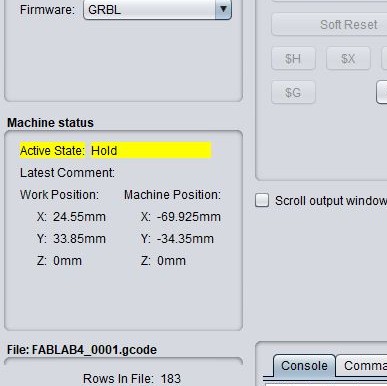
The machine status colimn will show the current status of the machine which is the position of the X,Y and the Z axis.
Applications
Vidya is an extremely versatile machine, designed to serve a wide variety of everyday and specialized drawing and writing needs. It can be used for almost almost any task that might normally be carried out with a handheld pen.
Some uses are:
- As a signature machine for checks, diplomas, headshots, etc
- As a "handwriting" machine for various purposes
- Digital artists can use Vidya to plot their artwork
Powered by w3.css