Week 10 : Input Devices
This weeks group assignment is to probe an input device digital and analog values.
- Digital Input: Digital input signals are used to represent items that only have two (2) states, such as... ON (binary 1) or OFF (binary 0) states. A digital signal is something like telling if a door is open or not.
- Analog Input: Analog signals are variable, they have multiple states. Analog input signals can represent such items as temperature or level or rate of flow. An analog signal is something like telling how much the door is open (or closed).
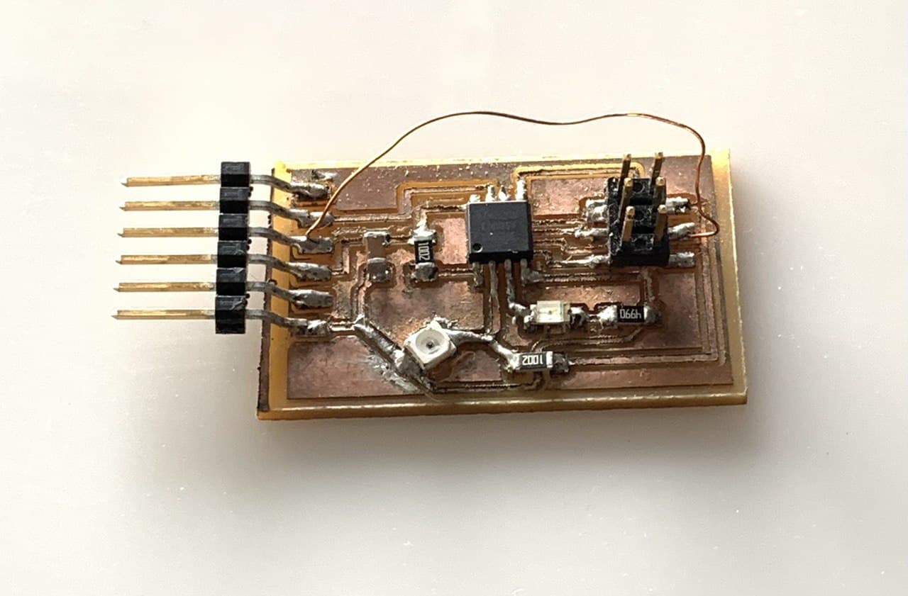
For conducting this weeks assignment we used a board with a phototransistor that was available in our lab.
Arduino Code
              #include <SoftwareSerial.h>
              #define RX 2
              #define TX 0
              #define photoTran 3

              int analogread = 0;
              int digitalread = 0;

              SoftwareSerial window(RX, TX);

              void setup(){
                pinMode(photoTran,INPUT);
                window.begin(9600);
              }

              void loop(){
                analogread = analogRead(photoTran);
                digitalread = digitalRead(photoTran);
                window.print("Analog value : ");
                window.println(analogread);
                window.print("digital value : ");
                window.println(digitalread);
                delay(300);

              }
We then flashed the program into the board and then connected the board to the computer using FTDI cable. We showed a torch light on the phototransistor from varying distances and the result in the serial monitor is as shown below.
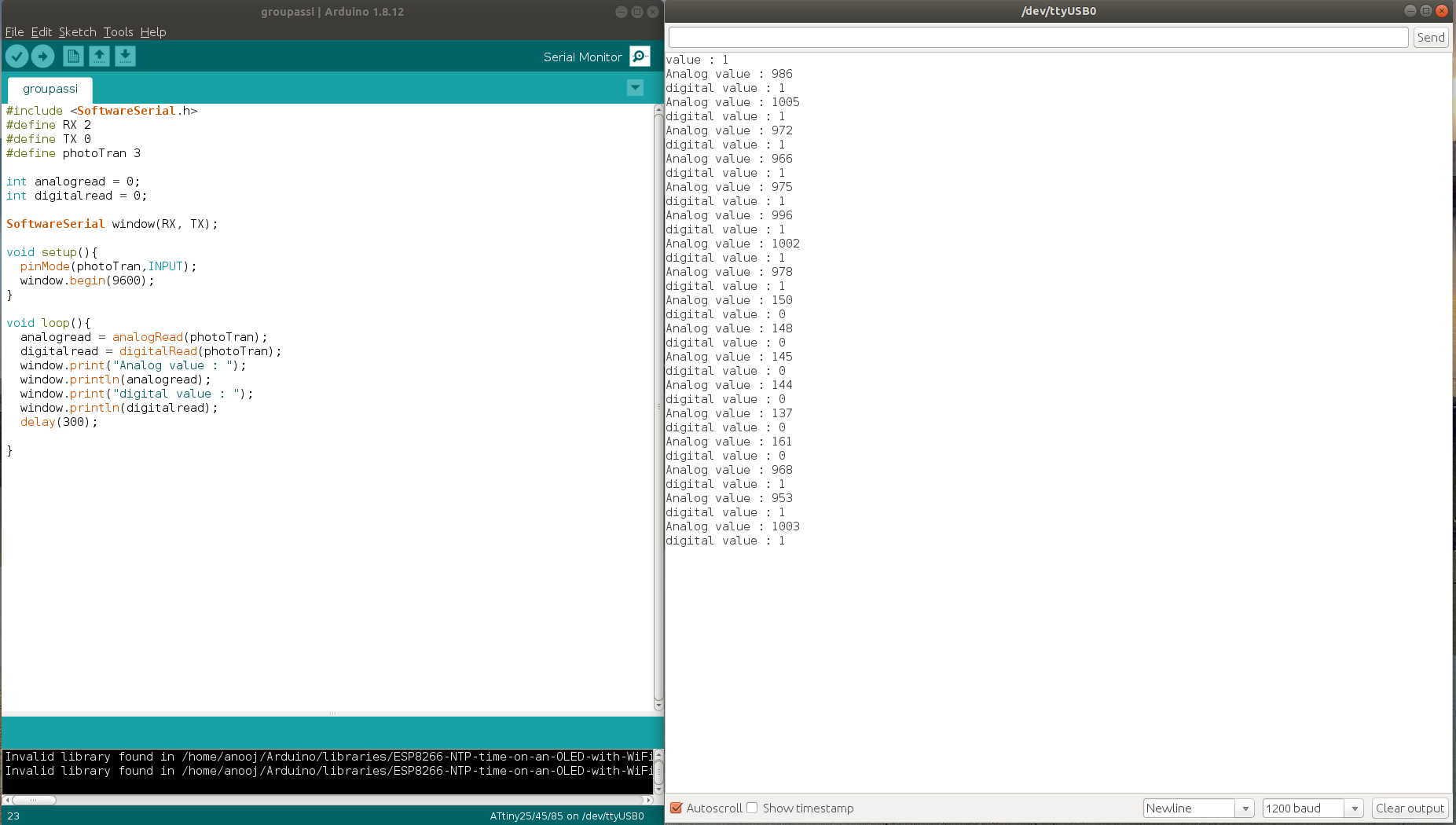
- The analog values where varying from a range of 130-1000 as we moved the light away from the phototransistor.
- The digital value was 0 when the light intensity was high and when the intensity was reduced the digital value became 1.
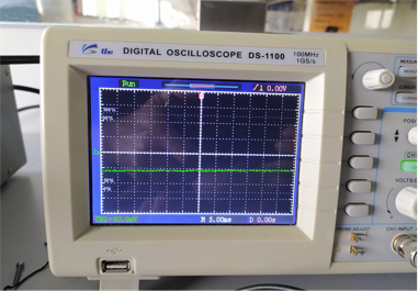
We then checked the analog signal using the Digital Oscilloscope
- When the light intensity is reduced by covering the phototransitor

- When the light intensity is increased by allowing light to fall on the phototransistor
Powered by w3.css