Fab Academy 2020
Introduction
This week main task is to build a group project and all the details of the project is mentioned in the group page. The machine which we built is a plotter "VIDYA" which as the name suggests, the plotter machine obviously draws or plots a drawing as per given instruction. It can draw most of the basic shapes, texts and even cartoons. It's operation is similar to the way a human hand writes. It is basically a 2.5 axis CNC machine, it has two stepper motors on both X & Y axis and a servo motor at Z axis. The pen is connected on the arm that makes the Y-axis, the servo motor that moves the pen up and down makes the z-axis. For my individual contribution i did electronics part of the plotter and nibin did the programming part and both of us together worked on effective movemnet of the machine. Additional informations can be found in the group page.
Arduino and Motor shield
Arduino Uno is a microcontroller board based on the ATmega328P (datasheet). It has 14 digital input/output pins (of which 6 can be used as PWM outputs), 6 analog inputs, a 16 MHz ceramic resonator (CSTCE16M0V53-R0), a USB connection, a power jack, an ICSP header and a reset button. It contains everything needed to support the microcontroller; simply connect it to a computer with a USB cable or power it with a AC-to-DC adapter or battery to get started
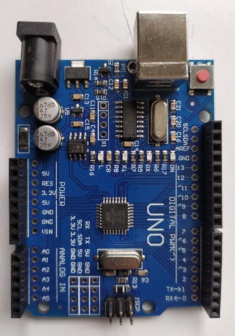
SO vidya works on a Arduino Uno platform. All the instructions for the movement of the machiene is fed into this board.
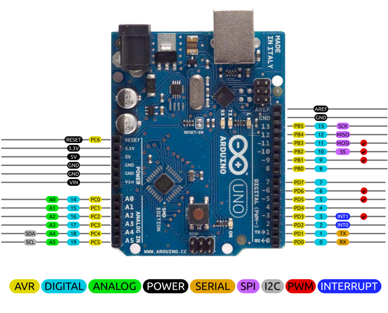
So its important to know the complete pin mapping of the Arduino board to place the step-motor shield.
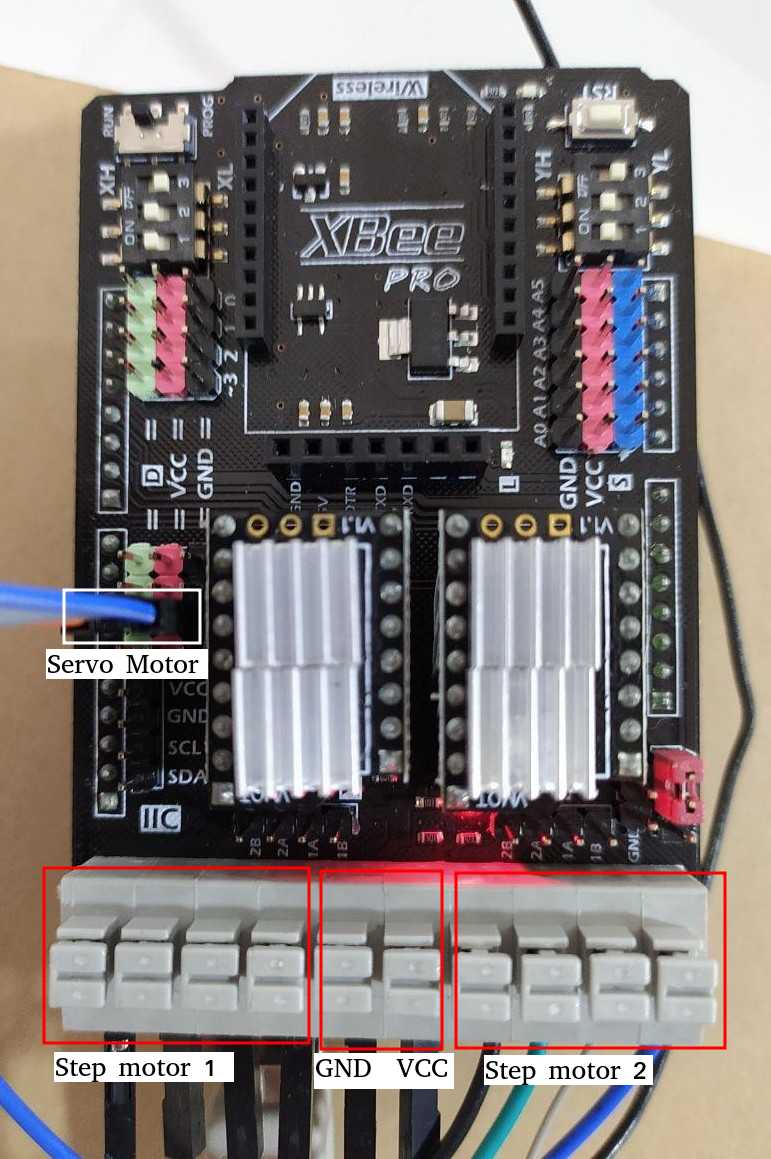
The Arduino Motor Shield allows you to easily control motor direction and speed using an Arduino. By allowing you to simply address Arduino pins, it makes it very simple to incorporate a motor into your project. It also allows you to be able to power a motor with a separate power supply of up to 12v.
Motor shield used here is Xbee pro which can be directly placed over the ardunio uno board and programmed for the desired movement.More information on the shield used can be found here .
GRBL Firmware
After assembling the machine the next step is to set the movement of the machine, i need to assign a firmware for precise movement of the machine.
What is Grbl Firmware?
The firmware is basically a preloaded set of codes and command which detects the input and outputs of the device. Now one device can only do work if its firmware can detect other commands. GRBL is an in-built software or firmware used in Arduino. Through this, one can use the Arduino easily. Now, this GRBL firmware can be installed in any version of the Arduino controller. For instance; Arduino UNO, Nano, Duemilanove, etc.
So, it is now understood what a GRBL is! Now the question is, how GRBL will be connected to the device? The simple answer is it uses the G-Code to control the hardware. So again, one question comes around. What is G-Code? So, G-code is a set of instructions through which one can design the code according to the necessity. Then they can port the instruction into the controller using the GRBL software. The most important point about the GRBL controller is it uses a simple USB port, where the other CNC controller uses the red or pink big pins to supply power as well as information. So, it is comparatively very handy. Because USB is very commonly available in the market, Arduino is not an exception to it. Additional information on CNC machienes can be obtained from this website.
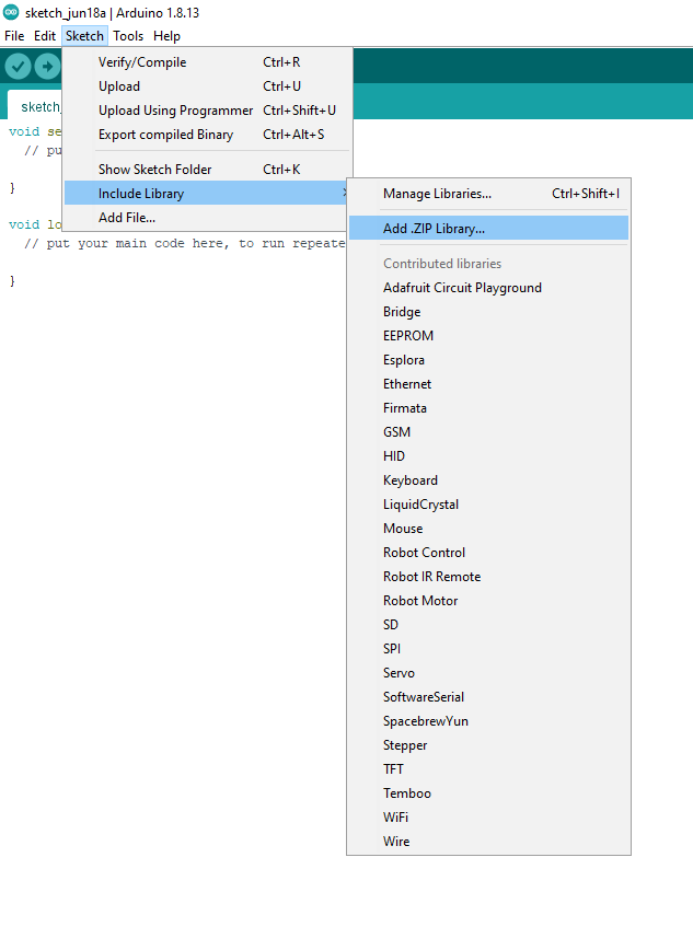
1) First step is downloading a firmware grbl. After reading a lot about differnt firmwares and after long search i downloaded a firmware . After the download, the file should be added in arduino as a library.Sketch => Include library => Add. Zip library-
And add the downloaded library.
2)After this process we have to edit the pins in the library, for that
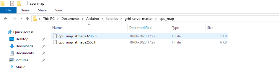
go to the arduino folder => libraries => grbl servo master => cpu map
and select cpu map atmega328p.h.
The pin should be changed in the cpu.map file which are selected regions in the upload file as shown below.
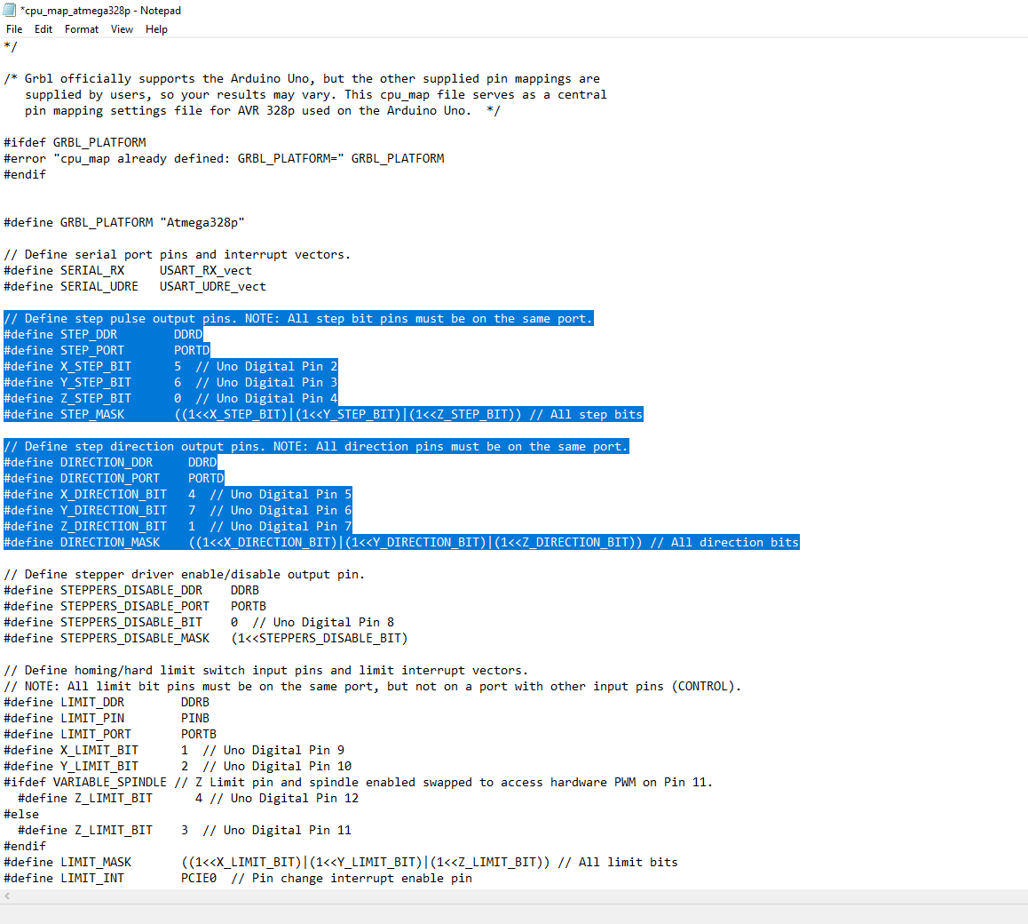

3) Next step is editing the pins in the selcted area.These pins are deicated pins to the various step motors used.
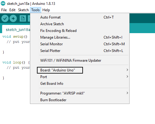
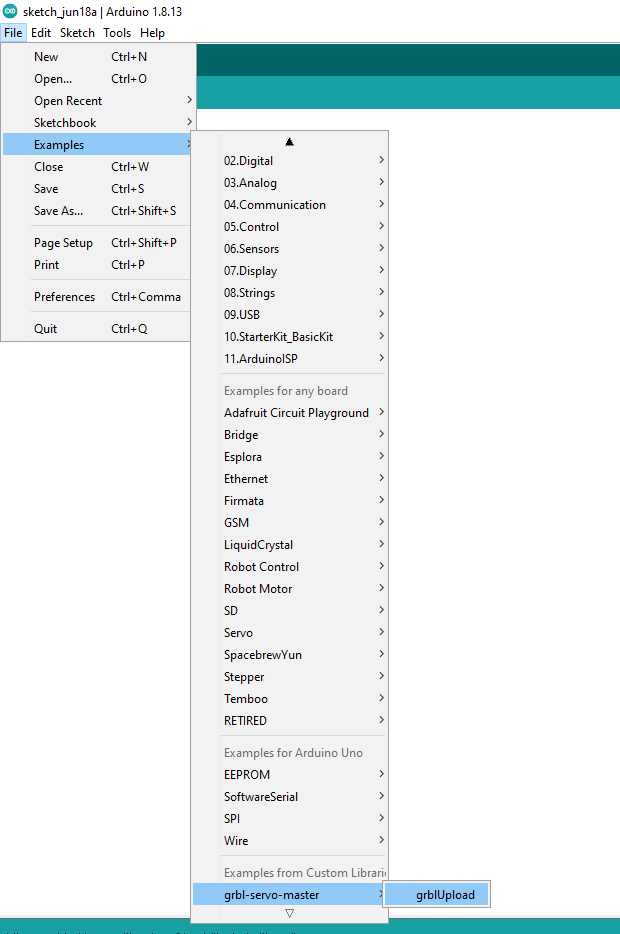
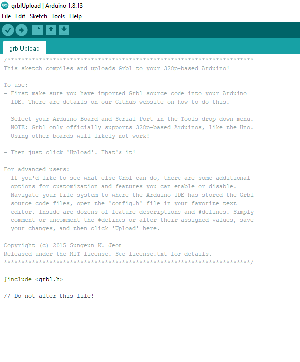
4) After assigning the pins open Arduino go to tools and change the board to ardunio uno as shown in the above pic. And then open examples => grbl servo master => grbupload as shown below. Once all this is done upload the program to arduino uno.
After grb-upload.
5.
Grbl-coreXY-servo to your Arduino.Tool => Board menu and the serial port is selected correctly in Tool => Serial Port.Calibration
After the caliberation process this values are entered into the interfacing software which is explained thoroughly in Nibins page.