MECHANICAL DESIGN MACHINE DESIGN.
So this weeks group assignments was to
- design a machine that includes mechanism+actuation+automation
- build the mechanical parts and operate it manually
- document the group project and your individual contribution
INTRODUCTION
So for this week we plnned to build a plotter which can draw shapes and texts.It is a 2.5 axis CNC machine which concists of two stepper motors both on X and Y and a servo motor for the movement of Z axis.
We divided the tast of building the plotter among the 5 of us,were me and Eldho Kurian were assigned to do the Electronics and Programming part.
Electronics And Programming.
In electronics and programming part our task was to program the Adruino UNO board and the DFrobot stepper motor shield board inorder for the stepper motors and servo to work,and to generate the gcode
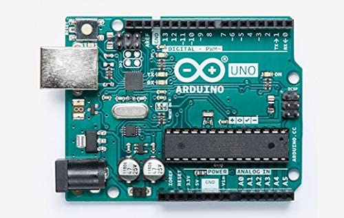
Adruino uno board
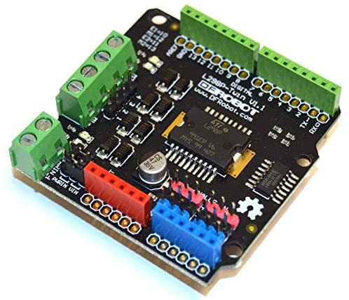
Dfrobot stepper motor shield
>
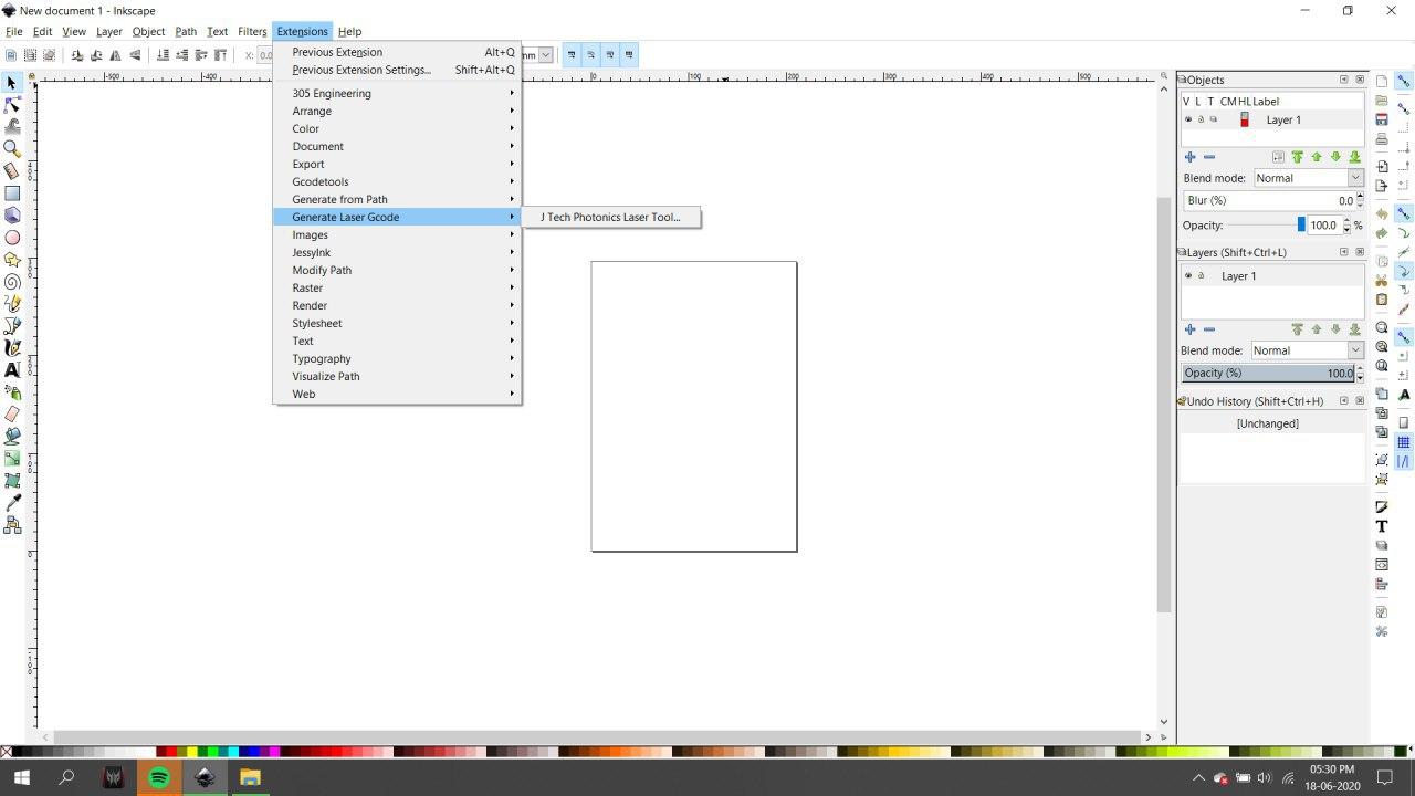
Generating Gcode
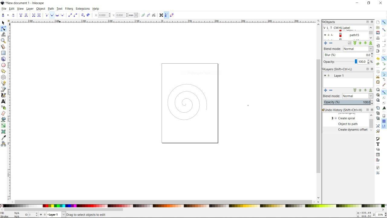
There are many softwares for generating gcodes,and many gcode generating softwares are available online.I used the vector design software Inkscape for generating gcodes becase i was familiar with software.Inkscape has got inbuilt Gcode generating extension for the new version .
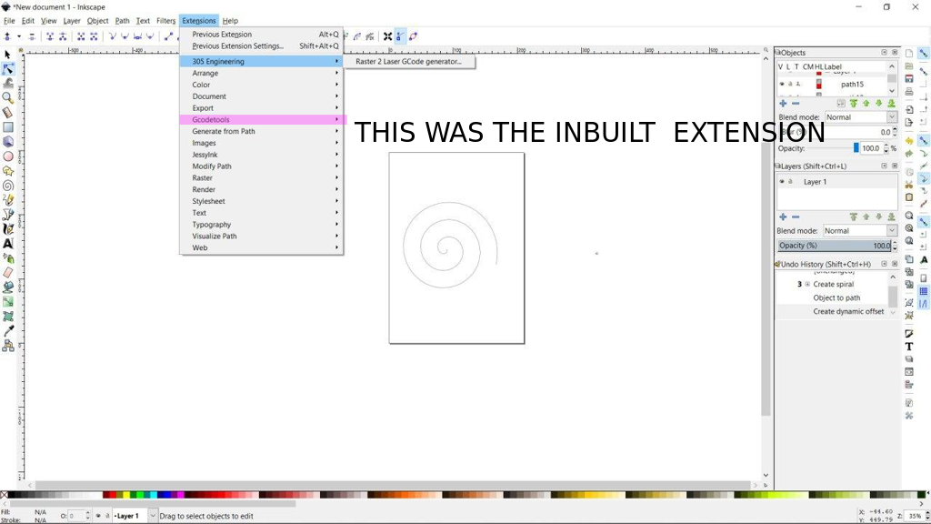
Luckly, for me it didnt work so i had to download anathor extension for generating gcode for inkscape.
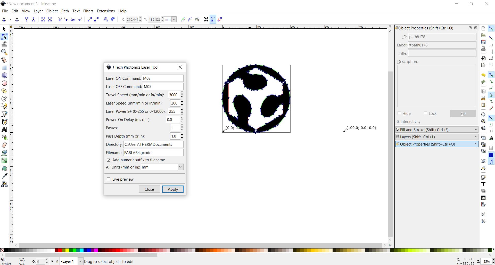
The extension i used is JTP Laser Tool Inkscape Plugin
[This Inkscape plugin will convert paths/drawing to G-Code for Vector Printing]
• Download the plugin from JTP Website
• Extract it using any good unzipping software.
• Put the contents of this .zip folder into the “inkscape\share\extensions” folder in installation directory.
• Once it is there it will show up under the “extensions” tab in Inkscape.
For processing gcode from Existing JPG/PNG Image in Inkscape
• Open Inkscape.
• Open the template you have downloaded in previous step according to your paper size.
• Click on File -> Import then select the JPG or PNG file from your drive and click open.
• Resize and position the image according to your page size.
• Image must be inside the boundaries of the page or G-code will not be generated properly.
• Right Click on the image and select Trace Bitmap.
• Select any of the Three Option [ Experiment and You will know the working] Brightness Cutoff, Edge Detection, Colour Quantization.
• Change the threshold according to the details you want in the drawing.
• Click on Update.
• Click OK and close the window.
• The Vector Bitmap will be overlapping the original picture.
• Drag out the original picture and delete it. You are ready to generate G-code.
• Now See G-code Generation Step.
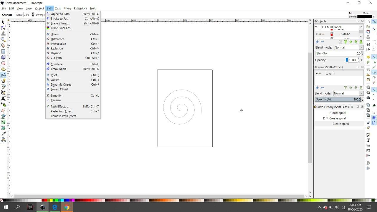
Processing from Custom Drawing in Inkscape
• Open Inkscape.
• Open the template you have downloaded in previous step according to your paper size.
• Start drawing or writing text inside the work area.
• Select all the objects by Ctrl+A shortcut.
• Group then together by Object -> Group from menu or by Ctrl+G shortcut.
• Then you have to convert object to path from menu Path -> Object To Path or by shortcut Shift+Ctrl+C. [ Important Step]
• Now See G-code Generation Step.
Gcode Sender
The next task is to send the generated Gcode to machine so that it draws the design.For this i used the platform Universal Gcode Sender.
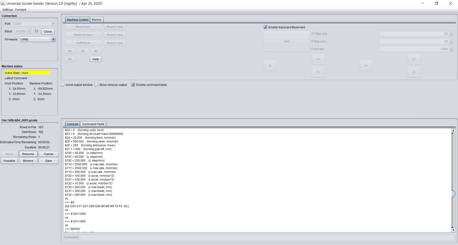
The Universal Gcode Sender will send G-Codes from laptop to Arduino UNO via USB Serial Port
• Download and install the version of Java listed on the download page according to your OS and system configuration. Requires Java 8.
• Download UGS Platform UGS Download
• Extract it using any good unzipping software.
• In the extracted folders locate bin in the ugsplatform directory.
• On Windows run ugsplatform.exe or ugsplatform64.exe, on Linux or Mac OSX run ugsplatform.
• No need of any installation or build.
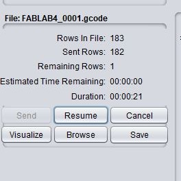
After setting up the Universal gcode sender we have to upload the previosly gcode file to the platform and send to the machine.
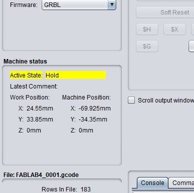
The machine status colimn will show the current status of the machine which is the position of the X,Y and the Z axis.