Fabacademy 2020
Week 1
Actually i have several projects in my mind. But i am not sure which one would fit the criteria of fablab.
1) Air conditioning is an expensive process and in developing countries its hard for common people to access airconditioning after coming back to home from scroching heat. At the same time the quality of air we breath is compromised due to pollution. So this project is on air purifying bladeless cooling fan which relies on venturi effect which consumes less energy and also innovation from nature.
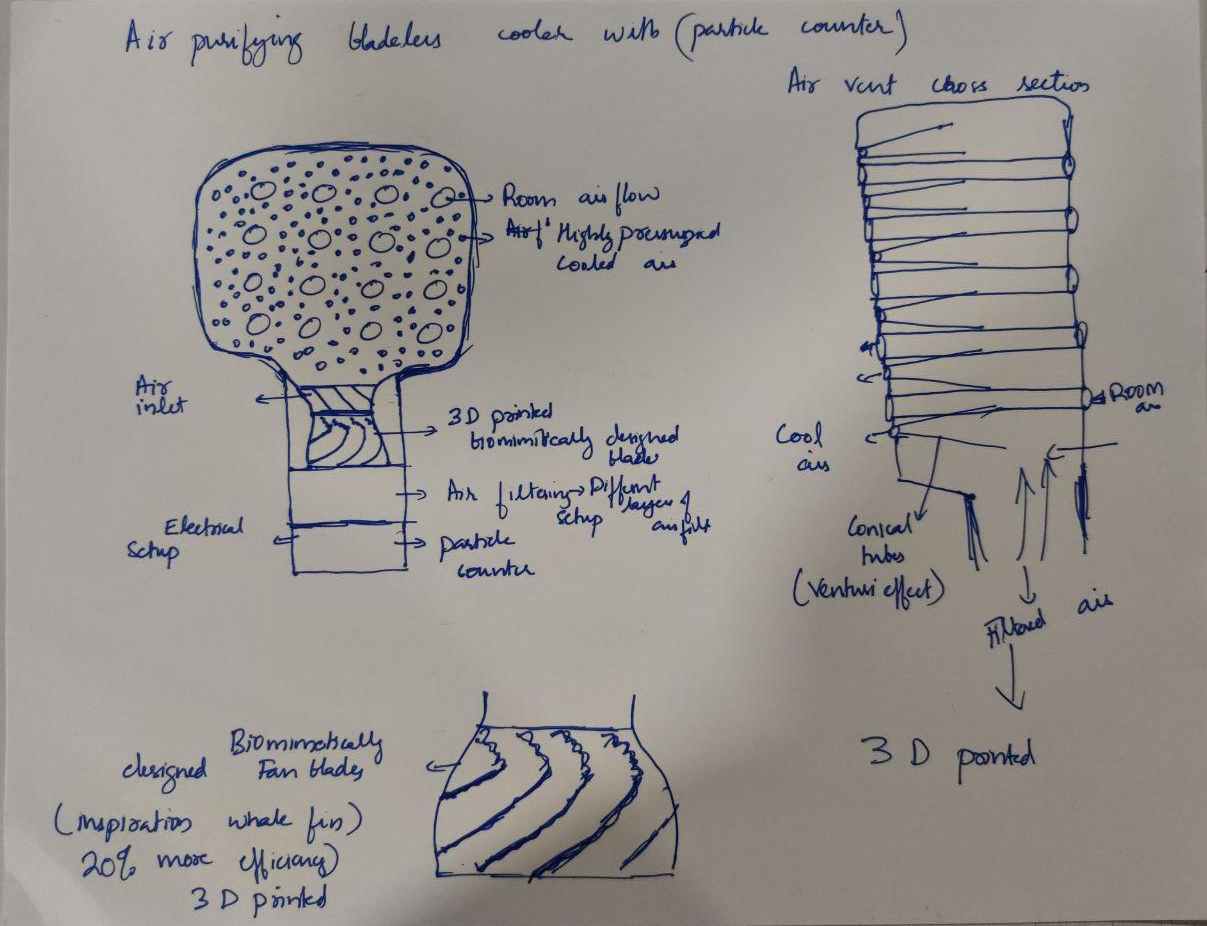
My idea here is to use resin 3d printing to print the fan blades and rest of the process i havent yet decided.
week 2
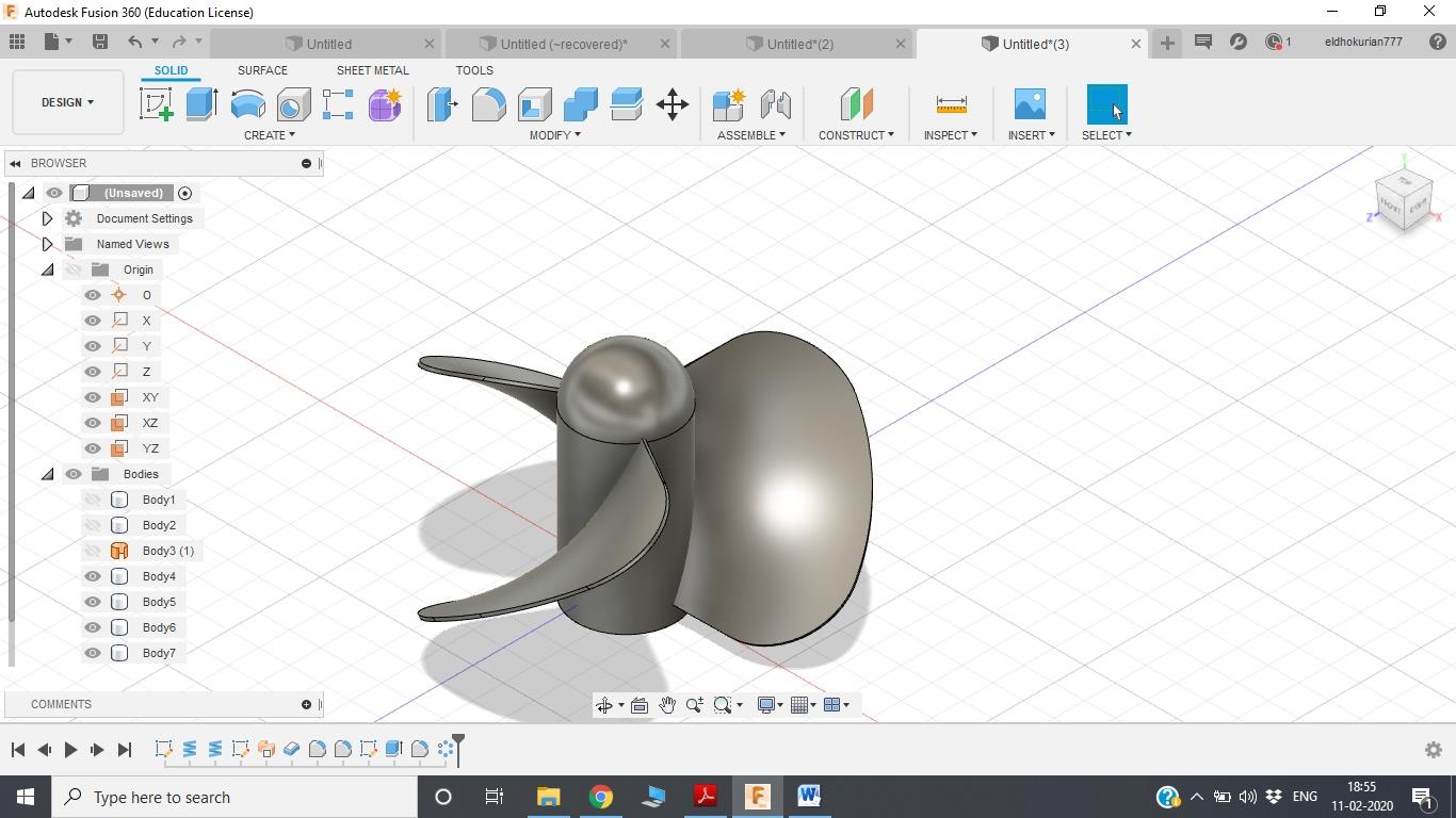
This week of designing. I learned a lot about different softwares and how important designing is to bring our imagination to the reality. Its a form of manifestation where we start to bring the imgination into life slowly. Since i have my final project in my mind i decided to make design a propellor . It was a hard process since i am new to fusion360.
week 3
I find vinyl cutting really interesting and i would defiently use some of these for my final project. It gives an artistic touch to the project.

week 4
I droped my previous project since i felt, it wont be feasible to make it the way i think.
So i decided to make an electrospinner which has multiple outlets for nano. micro fibers.
Electrospinning technology for nanofiber production is a widely used technique for the electrostatic production of nanofibers, during which electric power is used to make polymer fibers with diameters ranging from 2 nm to several micrometres from polymer solutions or melts. This process is a major focus of attention because of its versatility and ability to continuously produce fibers on a scale of nanometres, which is difficult to achieve using other standard technologies. Electrospinning is a relatively simple way of creating nanofiber materials, but there are several parameters that can significantly influence the formation and structure of produced nanofibers.
week 8 embedded programming
I started to think more about how to to execute my electrospinner project. Everything was working out fine, thats when it came to my notice DC to DC high voltage convertors are really expensive. Since i have to use very high DC voltage and low current, it cannot be possible for a handheld device to do that. So i decided to drop it, i had no other choice.
Lockdown time
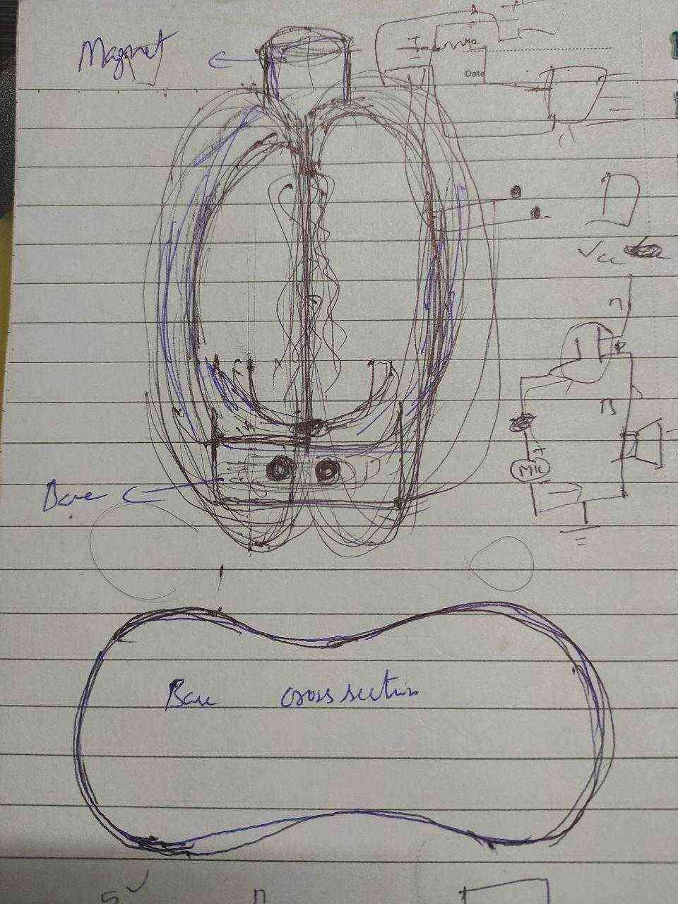
During lockdown i had plenty of time to think about a new project. I was constantly looking for new project and i saw random video. I came up with 2 new projects one dealing with ferrofluid and one with water both with music visualizing principle.
In ferrofluid project i wanted to move the fluid by varying the magnetic field and also move the fluid with music. Since i am from material science background i thought of synthesizing it myself, since its expensive to buy from external sources.
I got inspired from these videos and felt if this could be made in real life as an optical illusion, because watching water do crazy things is a stress reliever. I saw similar projects with light but didint fully understand the mechanism behind it.
week 9-Input devices
I did my input devices on rotary encoder, while doing rotary encoder i had in mind to use it as an input device which can be used to vary paramters in my final project.
week 11- Output devices
I used RGB board as my output device. For my final project i want to pulsate the led to certain frequency to achieve the optical illusion which i am looking for. It would be helpful to understand the basic functioning of LED. while doing this i understood the importance of PWM pin LED. And it helped me lot in my final project.
Interface and applications
Actually i started my final project during these week. Due to corona we where in strict lockdown for 3 months and even though i had lot of time to think about my project theoretically.
Project Development
A water based music visualizer based on cymatics, i have seen several videos in youtube where an illusion can be created using a video camera, speaker and a water hose.
Initial idea
As far as now i have seen several videos on how to create an optical illusion with water moving in certain patterns. Next step would be recreating this myself and see how this phenomenon works.
For this setup to work initially i would need a speaker-which can be colleted from any old speakers, an ampifier for the speakers, a water hose, a dc water pump, a signal geneartori- used a mobile app,a dc power source, and a mobile camera with settings to vary the frame rate.
First spiral
To execute the base idea i removed the magnet with diaphram from an old speaker. After that i attached a hose with 3 mm radius to the diaprgam using a glue gun and one end of the hose is connected to a 12 V DC water pump which is submersed in a water reservoir. The pump is connected to a DC power supply and once the pump is switched on water flows through the hose and the flow can be controlled by varying the voltage. To power the speaker a 12 volt amplifier is connected to the speaker and also to an aux cable.
The frequencies are gnerated using a mobile app. The aux cable is connected to the mobile and the app is switched on to produce low frequency sound waves.
4 types of sound waves can be produced using tone generator
when the complete setup is switched on the hose vibrates according to the frequency which is fed but no patterns are observed visually with naked eyes. But when recorded in a camera the effects and patterns can be seen clearly. So lets say if i use 30 frames per second to record the video and starting the frequency lets say sinewave. till 15 HZ only slight distrubences can be observed but with increasing the frequency the waves start to appear to move faster and in upward direction the waves slows down from 25 hz and stands still at 30 hz and moves in downward directinn with increasing frequency and also faster. When the frequency is increased beyond 50 hz the vibration become really fast with less movement and pattern. By increasing the amplitude the wave amplitude increases
Initially i made a trial setup to experiment with the pattern formation, which consisted of an amplifier, a speaker, and aux cable to connect with a device for frequency generation.
Later on, to improve the transfer of vibrations effectievly i 3d printed a small holder which is glued to the memabrane of the magnet. It helped to hold and position the hose properly asshown below..
Since there are different types of waves, i tried using sinewave first time and it showed really interesting results as shown above. It showed spiralling effects, conical spiral, and wavy motion.
After that i tried using square wave, in case of qaure wave the water showed effects like freezing drops. THe formation of drops is due to the energy distribution of square wave is differnt from sinewave.
By this initial experiment i understood the basics of this process, and was confiednt that it can be done using a speaker and pulsating the light.
Designing
The visualizer setup can be divided into 3 major portions
The base region should conist of an area for electrical board, an area for pump and water storage , and a slot for speaker(if possible or for future upgradation.). So while designing i should keep this in mind, the base should be wide enough to hold all this together and should be sealed from each other.
The midportion should be designed in the way, so that it can hold the setup by giving structural stability, it should have a path to route the wire and a base to place led.
The top portion should consist of a setup to hold the actuator on place so that the vibration does not affect the complete setup.
.jpg)
I actually designed my ferrofluid project with a glass upperpart and bottom part also but, i dropped the project since my ferrofluid synthesis process failed. And since i didnt have much time to continue synthesis i decided to go with my music visualizer project. So i gained some experinace designing something similar.
.jpg)
I got inspired from previously done projects and wanted to use balsa instead of acrylic. But with design since the parts i am using wont fit inside this design, i decided to make something bigger. WHich can fit all the components easily and later make it much more compact.
.jpg)
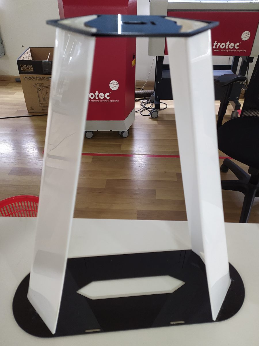
I decided to make a design with acrylic in mind. I made the base more broader and made the upper portion more parametric than the earlier organic design.So i decided to fit the water tank , pump and the electronic board in the bottom portion and the actuating system on the upper part.
Designing the complete setup was a such a complicated process.
3d printing
The water collecting setup was 3d printed using clear PLA. i felt that it would look good on the setup with lights shining.
Assembly process
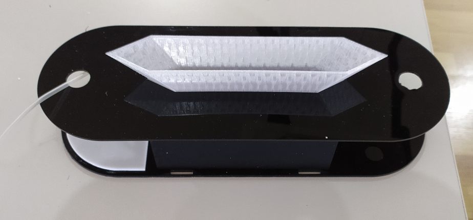
Main structure of the setup is made of acrylic and laser cutting is used to cut the acrylic. For the body i plan to use 2 mm thick acrylic and also plan to 3d print someparts. I used black and white sheets for the body.
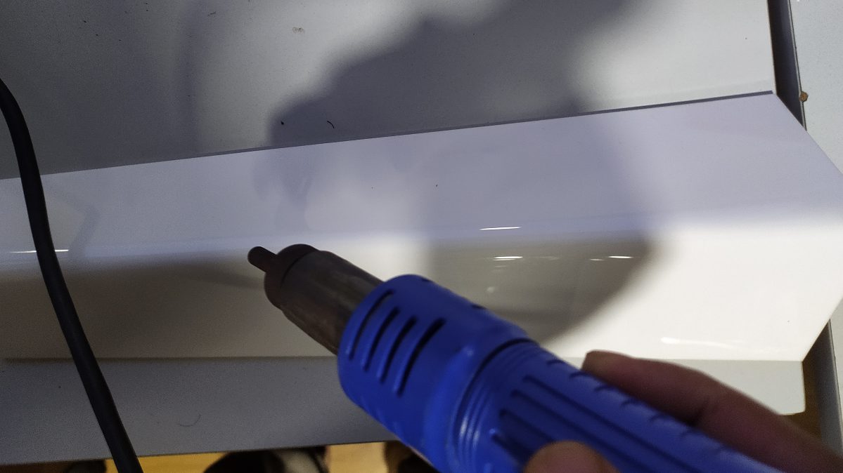
The mid part of the device was bent using a hot air blower and which was a long process since i need to bent 4 sheets. The blower is blowed throgh the midline of the sheet slowly for several times and when the the surface is hot.Its slowly bend by applying pressure at one side and for accuracy for how much to bent, i cut an acrylc sheet with an angle and used it to see how much more to bent.
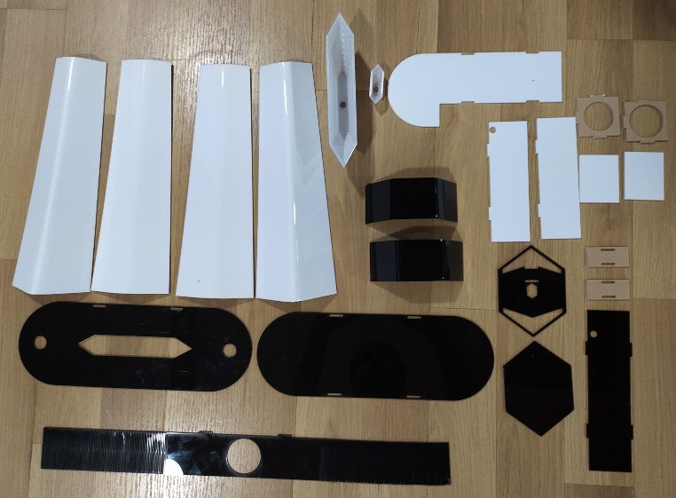
All the needed parts to assemble tthe body.
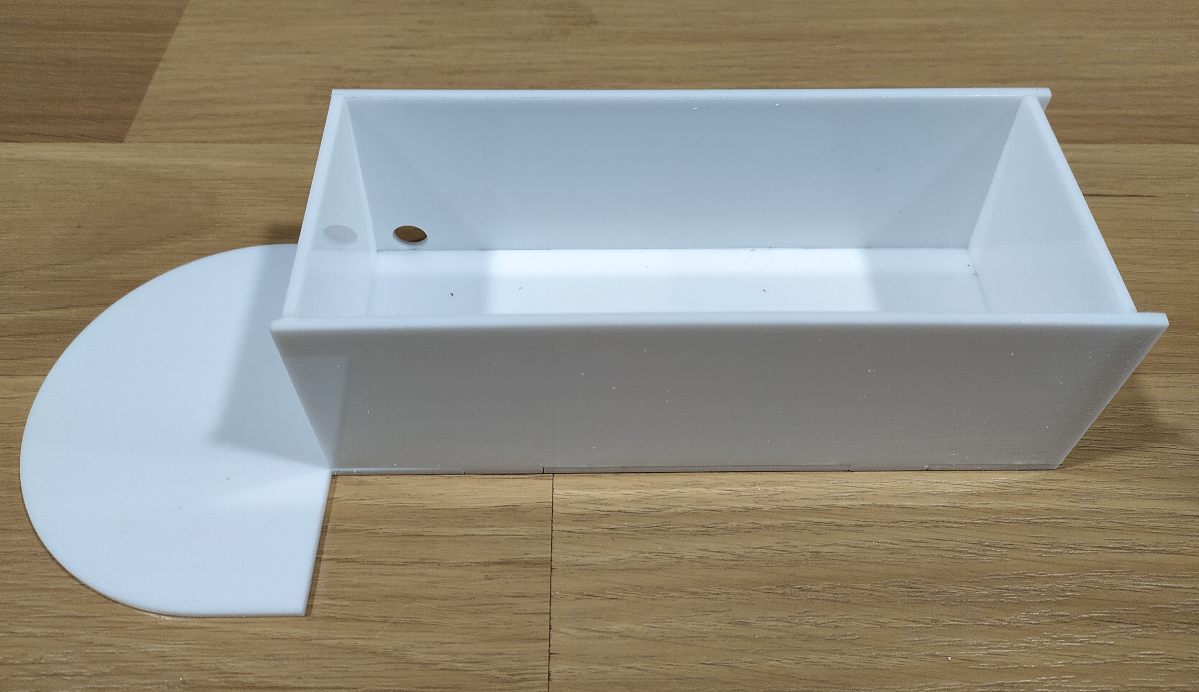
So i decided to start the assembly from the base. THe main part of the base is a watertank which is in the center and left and right side where i can place electronic components. I made a hole in the tank which can be used to remove water from the tank but later on i felt it was a bad idea. The tank is sealed by using a glue gun where all the edges are sealed by glue by a special technique of sealing. where the glue gun is moved in the forward direction at constant speed.
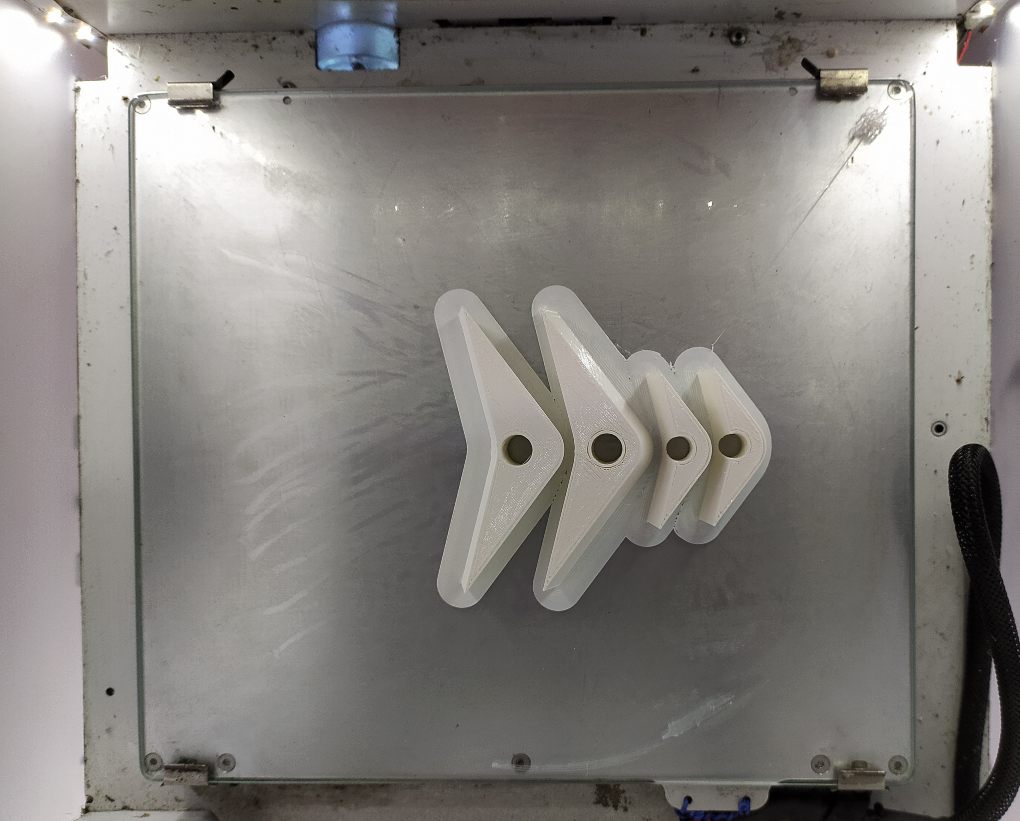
TO join the four mid section which was bent earlier i decided to print four pieces with required angle and a hole in the middle for passsage of wire and water tube.
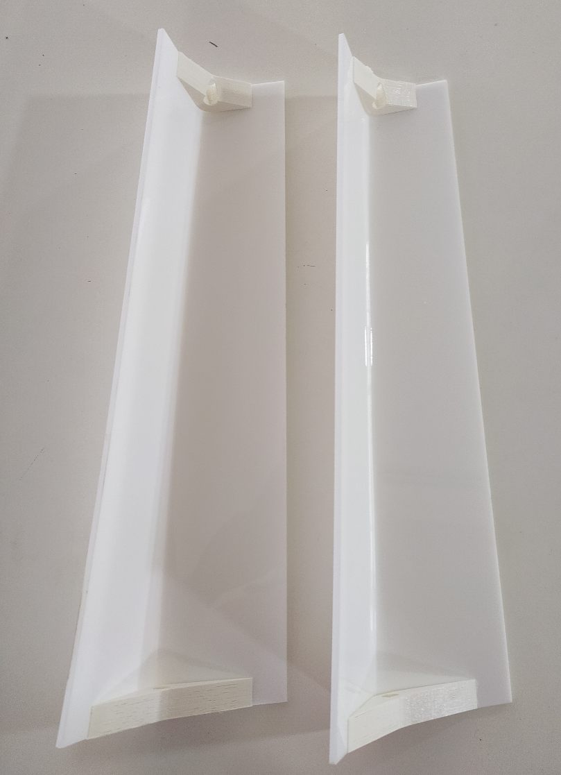
The 3d printed pieces where stuck to the midsection using glue. Later on i felt i could have done this in a different way.
THe bottom setup with all the necessary components. The central water collector which is 3d printed by PLA filment.
The water colletor has a hole in the center so that the water can flow to water tank.
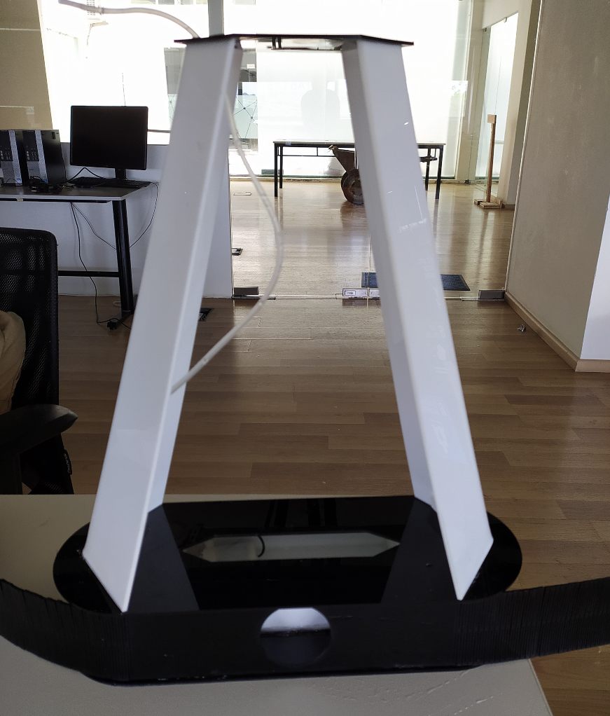
The mid section with an attachment for the top and bottom portion.
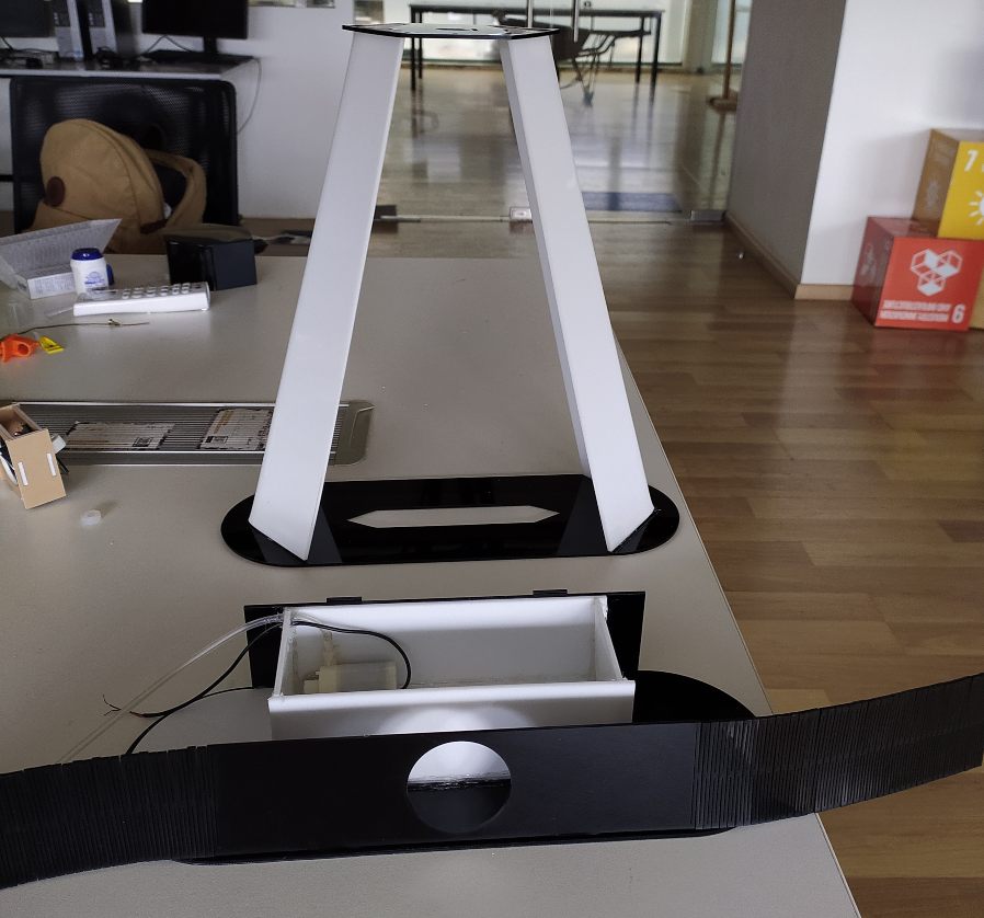
THe bottom section with the water pump pump and exit for the wire and the tube attached to the pump.
After attaching the base to the midsection.
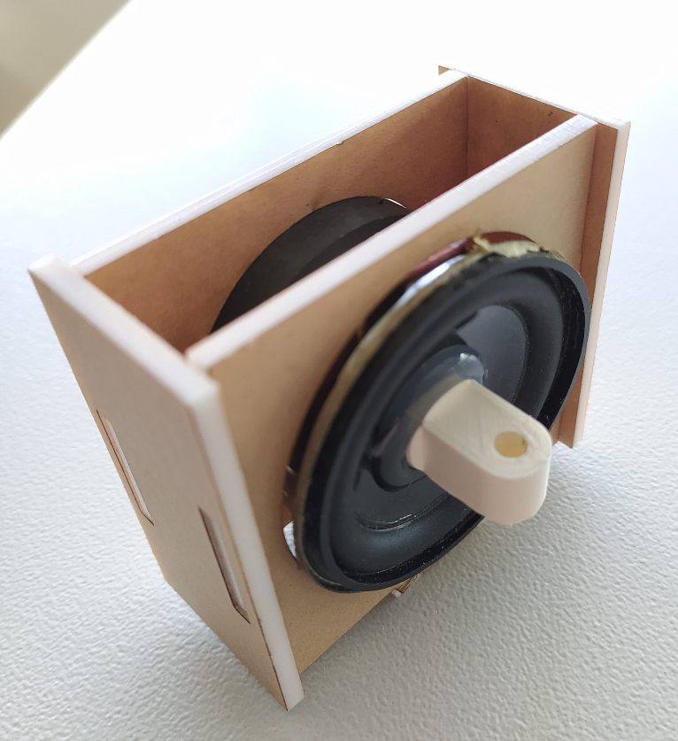
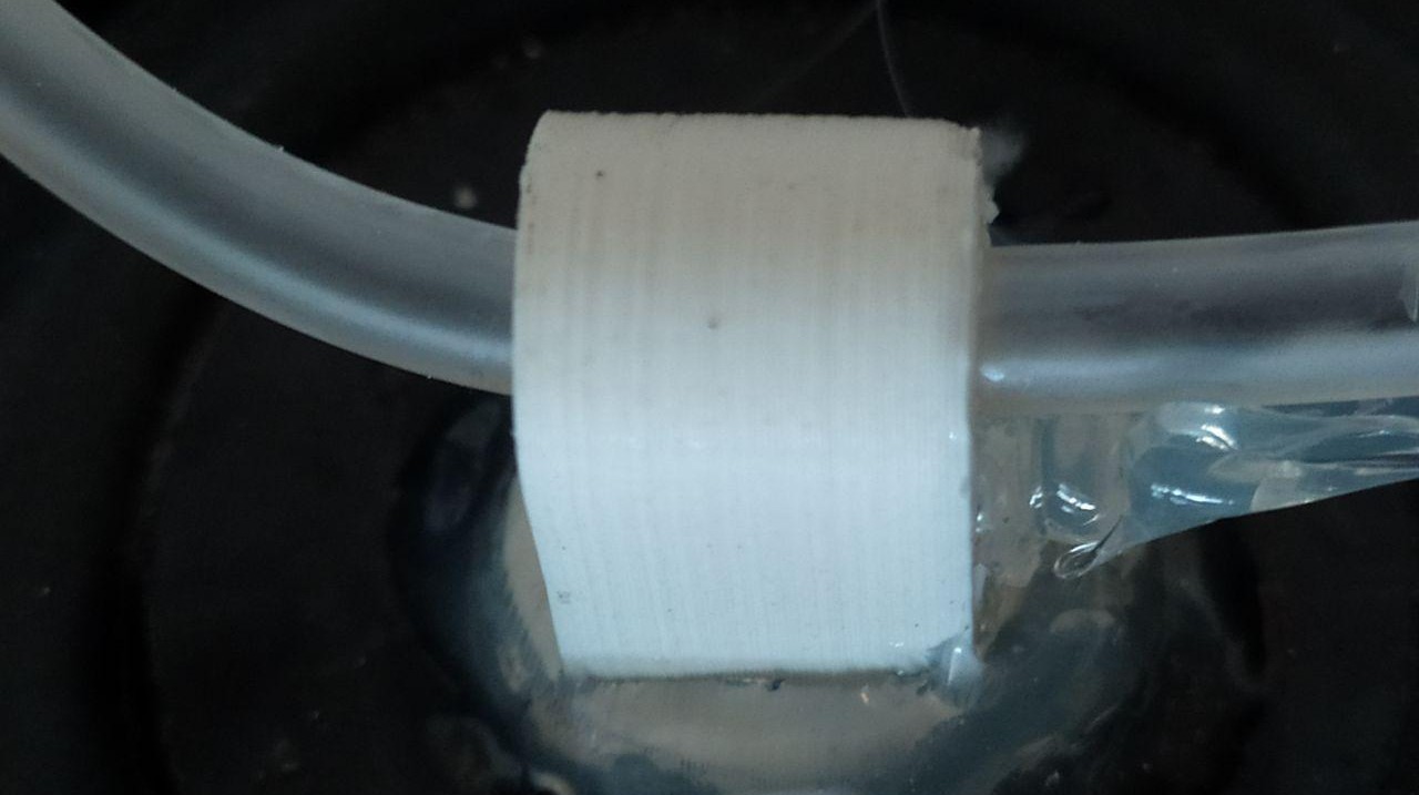
A setup to hold and magnet which can be fixed on to the top section. A 3d printed water tube hoder is attached to the diaphram using a glue gun.This holder helps in effecievly trasnfering the vibrational displacemnt of diaphram
Electronic Designing
After completion of the external setup to an certain extent. I kept it aside and started working on making electronics board.
Inorder to start the electronics portion i need a rough estimation of what all components are required.
So the main components which i need to connect are
The main fucntions which i need to execute is
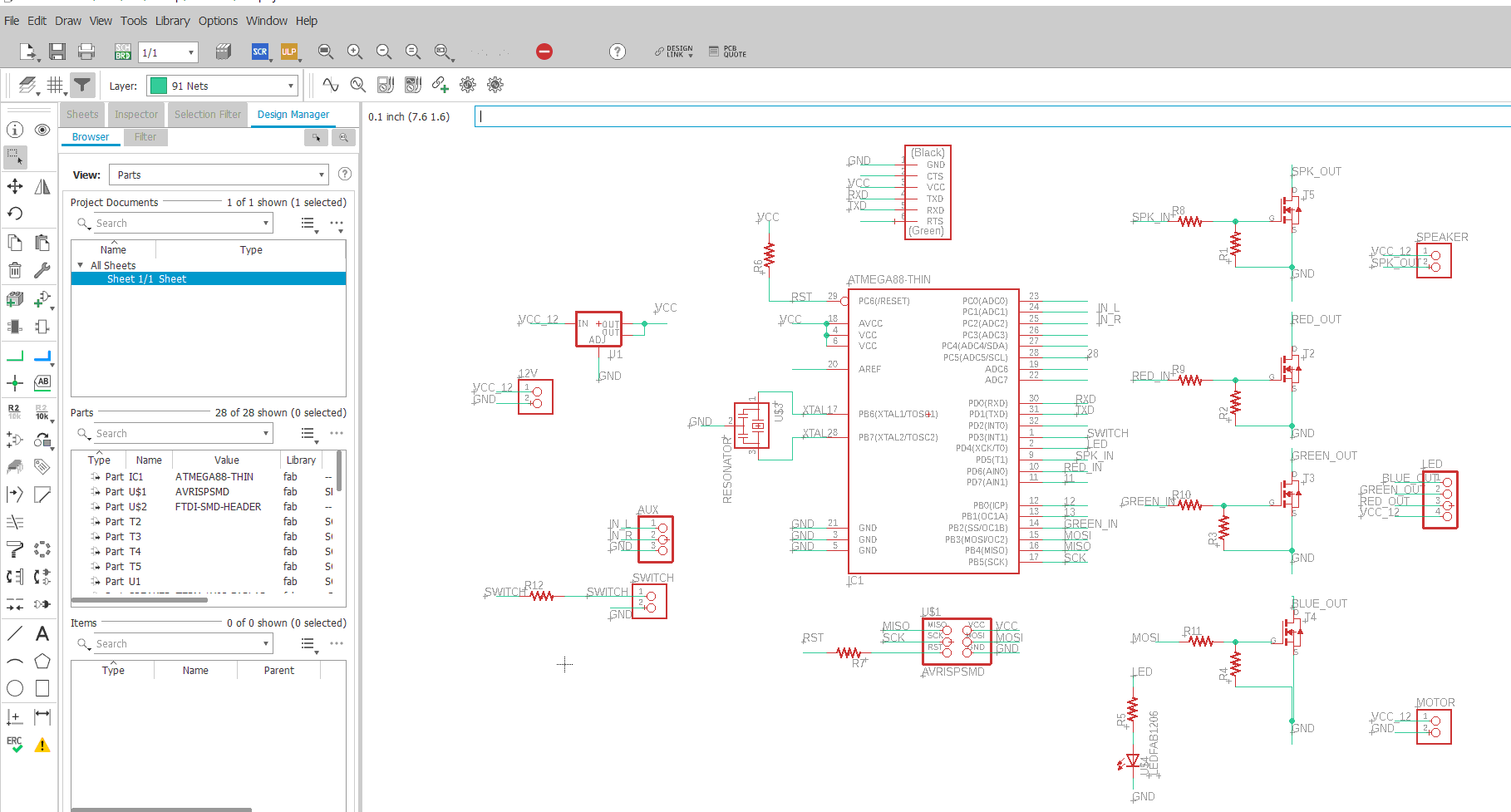
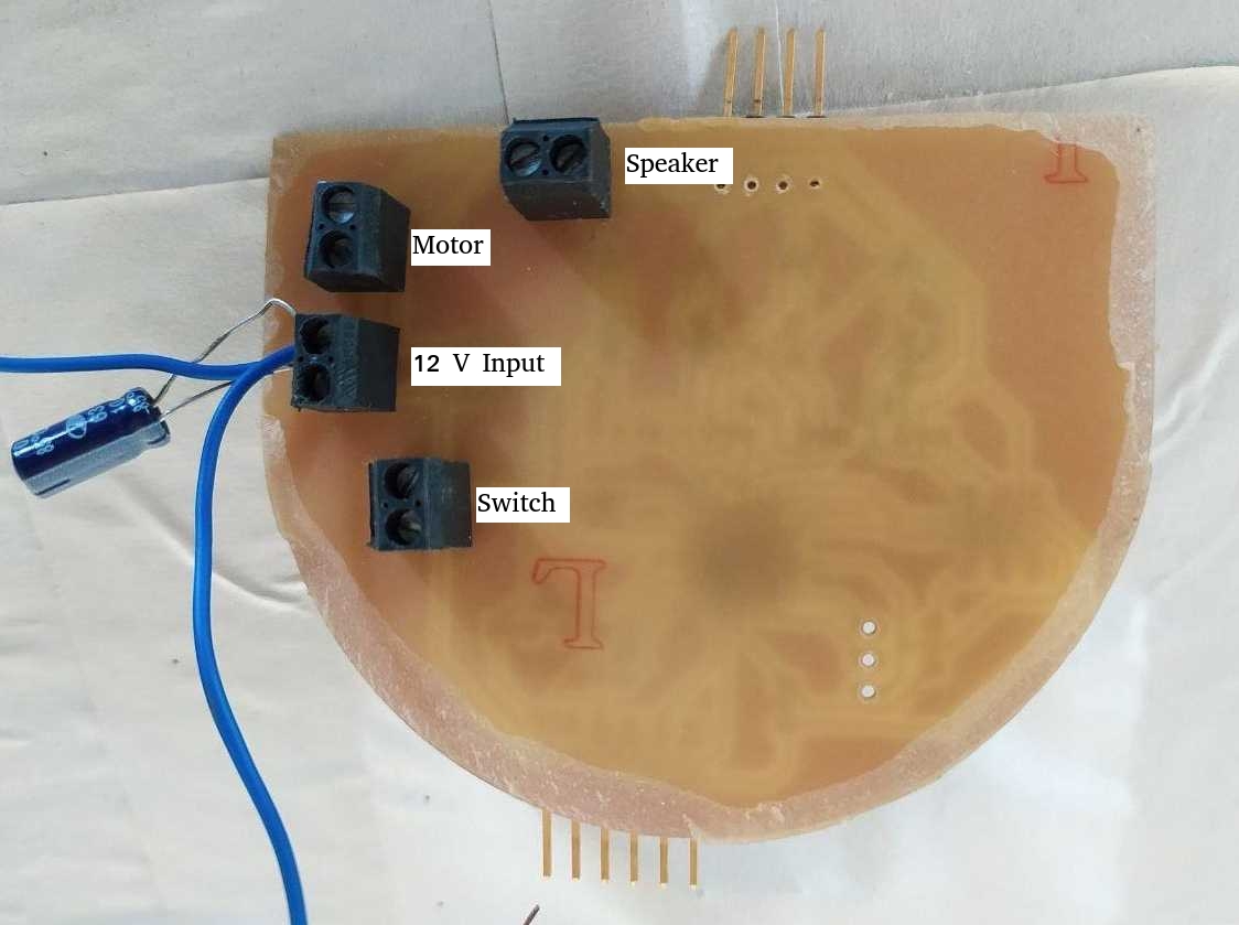
Inorder to incorporate all this i decided to use atemga 328p. Since i cannot use microcontroller to power up and pulsate 12 V RGB LED( microcontroller works at 5V). I need MOSFET to pulsate the LED and the speakers. I have to use a voltage regulator to supply voltage to microcontroller since i am using power from external source. And some termnial blocks to connect the different components to the board. Keeping all this in mind i started to make the schematics.
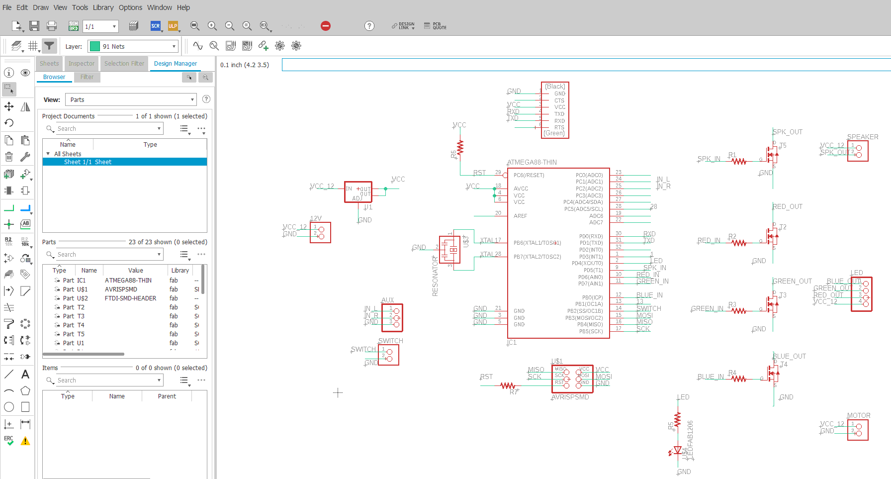
After the schematics is done i have to make the board,considering the main design.
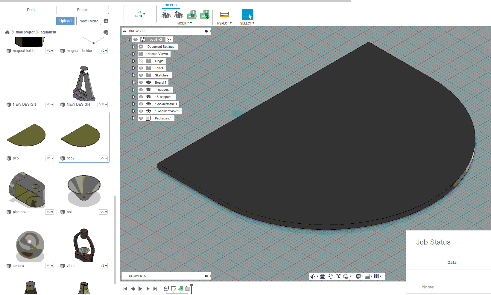
For that i first made a PCB board in fusion 360. WIth a required parameter which can be easily fit into the setup.
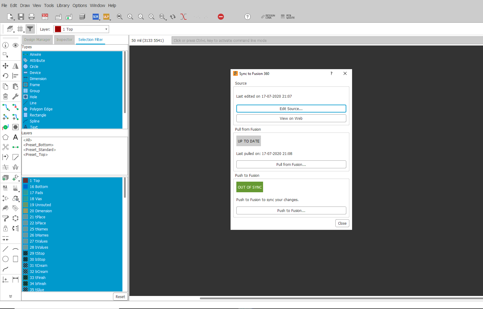
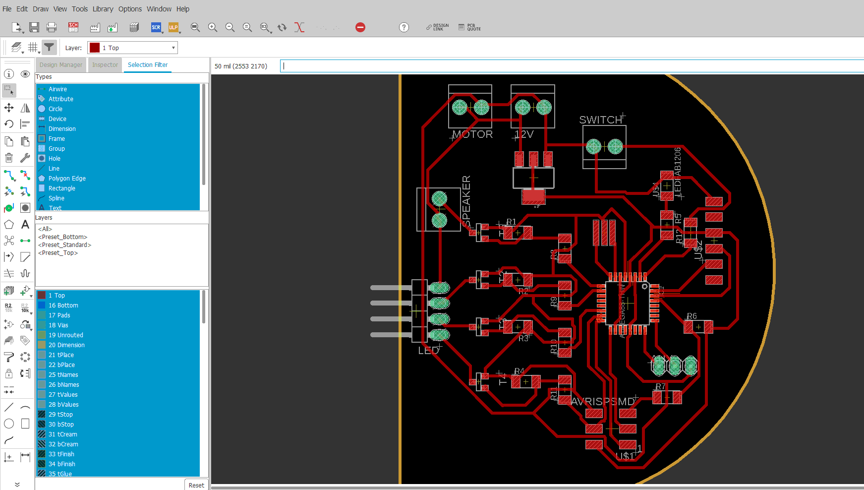
In the next steps, I opened eagle and using the pull design from fusion option i got work space with a sketch of the board.
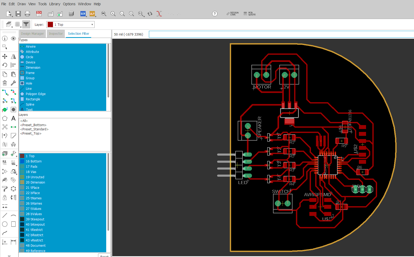
After manually routing the board diagram.
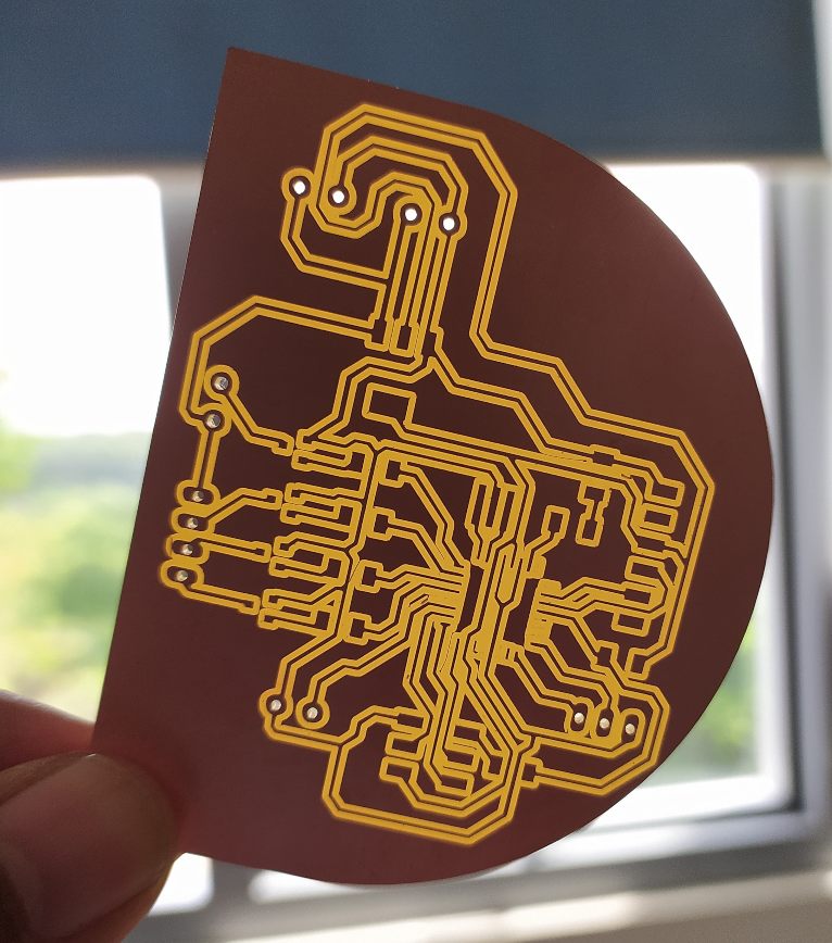
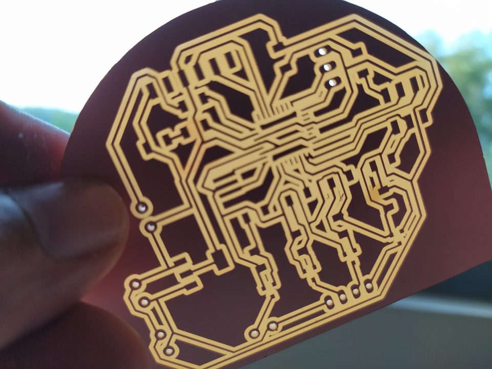
After PCB milling. the path can be clearly seen.
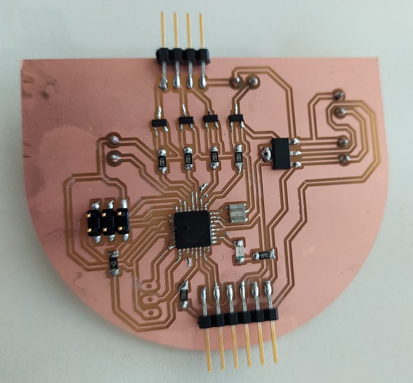
After soldering the board. Everything looks perfect. But there is a problem with the transistors used. When using the board for testing some errors happend and after some analysis there is some correction needed for the transistor circuit. I misplaced the resistor for the mosfet circuit and mosfet didint work properly.
I started working on the new board with revised circuit.
After correction to the transsitor circuit.
After milling
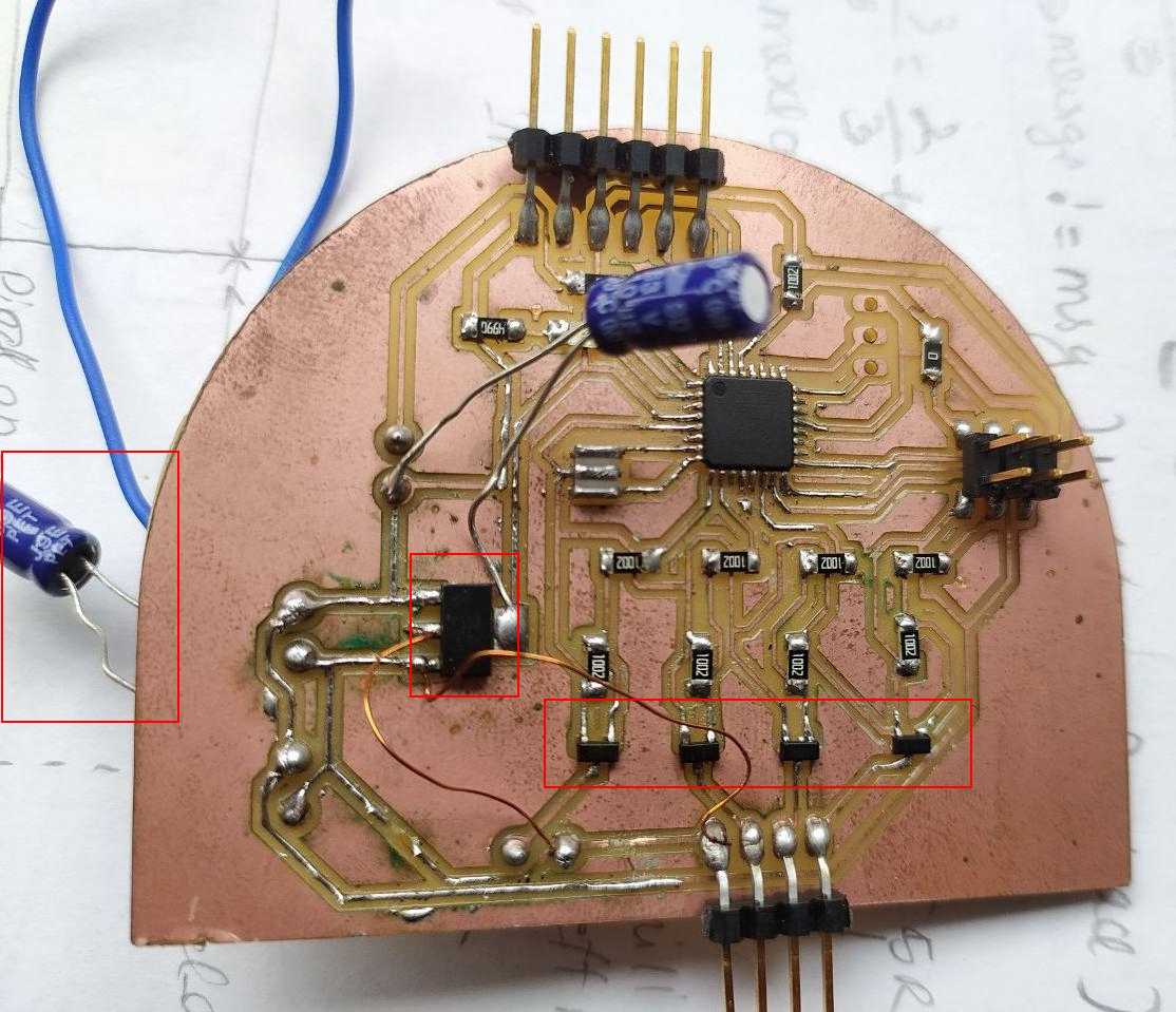
The main components here is Mosfet, which switches on and off to produce frequency.A voltage regulator to control voltage.
Capacitor is placed across the input power to avoid voltage spikes when the board is switched on. This is due to presence of water pump which can cause voltge drop.
Programing
Inorder to give the frequency to the speaker and to the led we have to write a program. I did the programing using arduino. So inorder to do the programing we have to first add the Atmega 328p library to the board manager.
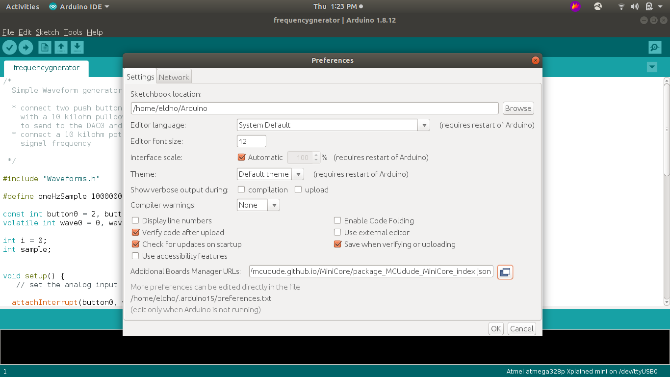
Board manager installation
File > Preferences menu item.https://mcudude.github.io/MiniCore/package_MCUdude_MiniCore_index.json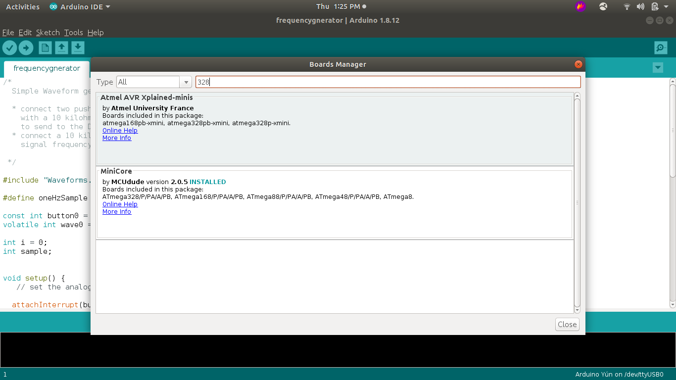
Tools > Board > Boards Manager... menu item.
Minicore and click InstallFOr information about the installation and atmega minicores can be found here.
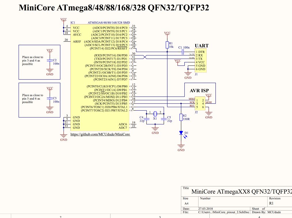
A schematic of a simple closed circuit using Atmega328p. this helps to identify the basic connections.
Atmega328 has one 16 bit timer, which is more powerful comparing to 8-bit timers. A 16-bit timer is called Timer/Counter1. Counter1 has twice more bits than 8 bit Counter0, so you get more counts leading to longer duration and more precise timings. I used 16 bit timer for pulsating purpose.
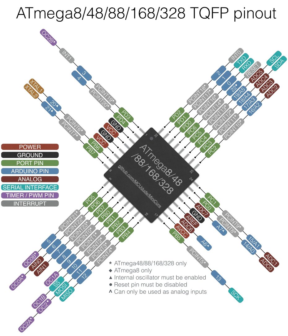
Atemga 328p pin map, it is necessary to cross check the pin map to have a clear cut idea of pins, since it has lot of pins.
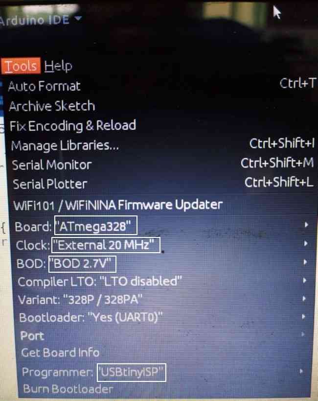
As shown above enter the neccessary configurations to burn Bootloader
After burning the bootloader, since i have placed an led in the circuit i tried to test program the led to see if the board works properly.
The main program is divided into different parts
bool flag = 0;


	void setup() {
	  Serial.begin(9600);
	  pinMode(10, OUTPUT);
	  pinMode(6, OUTPUT);
	  pinMode(11, OUTPUT);

	  digitalWrite(6, LOW);
	  digitalWrite(11, LOW);
	  init_PID();
	}

	void loop() {


	}

	void init_PID() {
	  cli();               //stop interrupts

	  // set timer1 interrupt at 1Hz------------------------
	  TCCR1A = 0;          // set entire TCCR1A register to 0
	  TCCR1B = 0;          // same for TCCR1B
	  TCNT1  = 0;          //initialize counter value to 0

	  // set compare match register for 1hz increments------
	  OCR1A = 651;         //(16*10^6) / (40*1024) - 1 (must be < 65536)

	  // turn on CTC mode ----------------------------------
	  TCCR1B |= (1 << WGM12);

	  // Set CS12 and CS10 bits for 1024 prescaler ---------
	  TCCR1B |= (1 << CS12) | (1 << CS10);

	  // enable timer compare interrupt --------------------
	  TIMSK1 |= (1 << OCIE1A);

	  sei();               //allow interrupts
	}

	ISR (TIMER1_COMPA_vect)
	{

	  digitalWrite(10, flag);
	  flag = !flag;


	}
		#define switch1 3
		#define ledr 10
		#define ledg 6
		#define ledb 11
		#define speaker 5
	   bool flag1 = 0,flag2=1,flag3=0;
		 int sw=1,ocr1;
		 int tim=10;

	   void setup() {
		 Serial.begin(9600);
		 pinMode(ledr,OUTPUT);
	   pinMode(ledg,OUTPUT);

		 pinMode(speaker,OUTPUT);
		 pinMode(switch1, INPUT_PULLUP);

		 pinMode(ledb,OUTPUT);
		 digitalWrite(6,LOW);
		 digitalWrite(10,LOW);
		 digitalWrite(11,LOW);
		 digitalWrite(speaker,LOW);

	   attachInterrupt(digitalPinToInterrupt(switch1),updateocr1, FALLING);

		 init_PIDt1();

	   }

	   void loop() {
		 digitalWrite(ledb,(flag3||flag2));
		 digitalWrite(ledr,(flag3||flag1));
		 digitalWrite(ledg,LOW);

		 delayMicroseconds(abs(10-tim));

		 flag3=!flag3;


	   }


	   //Timer interrupt 1
	   void init_PIDt1() {
		 cli();               //stop interrupts

		 // set timer1 interrupt at 1Hz------------------------
		 TCCR1A = 0;          // set entire TCCR1A register to 0
		 TCCR1B = 0;          // same for TCCR1B
		 TCNT1  = 0;          //initialize counter value to 0

		 // set compare match register for 1hz increments------
		 OCR1A = 217;         //(16*10^6) / (40*1024) - 1 (must be < 65536)

		 // turn on CTC mode ----------------------------------
		 TCCR1B |= (1 << WGM12);

		 // Set CS12 and CS10 bits for 1024 prescaler ---------
		 TCCR1B |= (1 << CS12) | (1 << CS10);

		 // enable timer compare interrupt --------------------
		 TIMSK1 |= (1 << OCIE1A);

		 sei();               //allow interrupts
	   }
	   void updat_PIDt1() {
		 cli();               //stop interrupts

		 // set timer1 interrupt at 1Hz------------------------
		 TCCR1A = 0;          // set entire TCCR1A register to 0
		 TCCR1B = 0;          // same for TCCR1B
		 TCNT1  = 0;          //initialize counter value to 0

		 // set compare match register for 1hz increments------
		 OCR1A = ocr1;         //(16*10^6) / (40*1024) - 1 (must be < 65536)

		 // turn on CTC mode ----------------------------------
		 TCCR1B |= (1 << WGM12);

		 // Set CS12 and CS10 bits for 1024 prescaler ---------
		 TCCR1B |= (1 << CS12) | (1 << CS10);

		 // enable timer compare interrupt --------------------
		 TIMSK1 |= (1 << OCIE1A);

		sei();               //allow interrupts
	   }
	   ISR (TIMER1_COMPA_vect)
	   {
		 digitalWrite(speaker, flag2);


		 flag1 = !flag1;
		 flag2= !flag2;


	   }

	   //Timer interrupt


	   //UpdateOCR1

	   void updateocr1()
	   {

		 switch(sw)
		 { case 1:
		 ocr1=651;
		 sw=2;
		 tim=10;
		 break;
		 case 2:
		 ocr1=673;
		 sw=3;
		 tim=11;
		 break;
		 case 3:
		 ocr1=697;
		 sw=4;
		 tim=15;
		 break;
		 case 4:
		 ocr1=630;
		 sw=5;
		 tim=8;
		 break;
		 case 5:
		 ocr1=610;
		 sw=6;
		 tim=5;
		 break;
		 case 6:
		 ocr1=434;
		 sw=7;
		 tim=7;
		 break;
	   case 7:
		 ocr1=325;
		 sw=8;
		 tim=8;
		 break;
		 case 8:
		 ocr1=217;
		 sw=1;
		 break;
		tim=9;
	   }
	   updat_PIDt1();
	   }
Vinyl cutting
Previously in the computer controlled cutting week, I got familier with vinyl cutting and found it very interesting. I did lot of cuts and came across these african tribal symbols, each of which mean a a unique personailty trait a person should have. I found it interesting anfd thought of using it for my project.

I decided to use a vinyl cutting to stick this pattern on the midsection. So when the light shines through the vinyl there is a shadow effect.
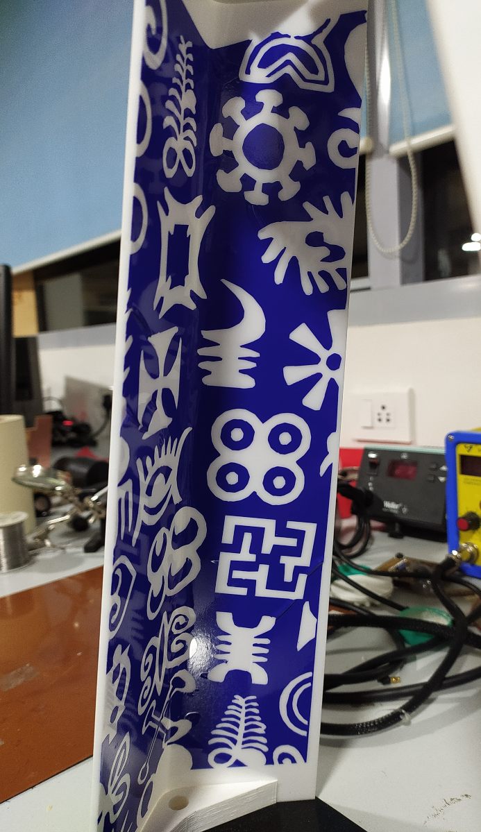
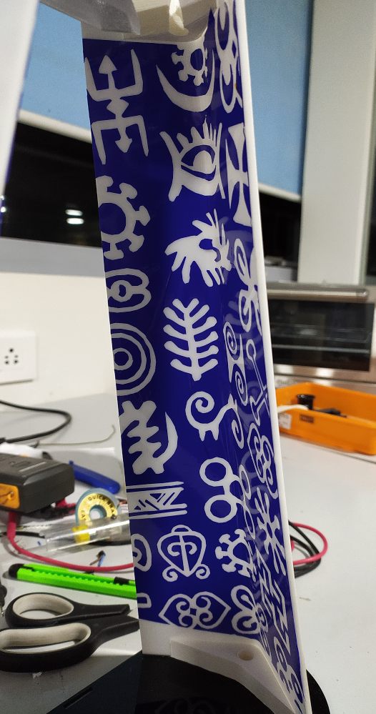
It was a hard process to transfer the vinyl on mask to the midsection. Mainly due to the angular shape. but after some trial and error i made it.
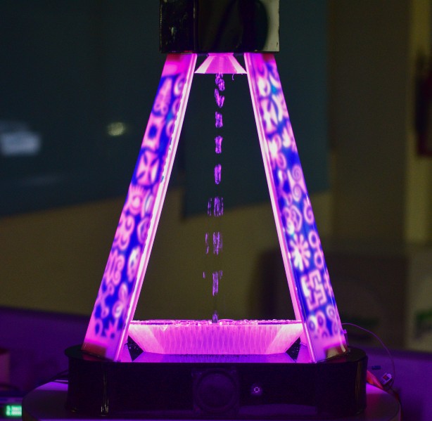
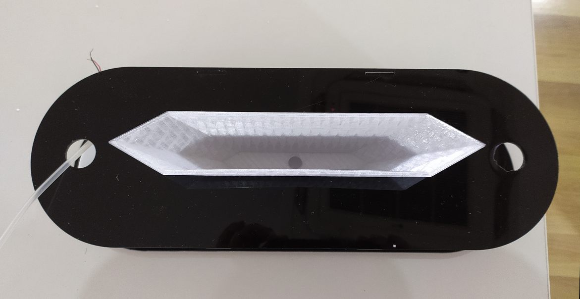
This is how vibradrop looks in the dark.