Mechanical Design, Machine Design. (WEEK 17 )
           *Assignment*

           ‣ Design a machine that includes mechanism + actuation + automation
           ‣ Build the mechanical parts and operate it manually.
           ‣ Actuate and automate your machine.
Introduction
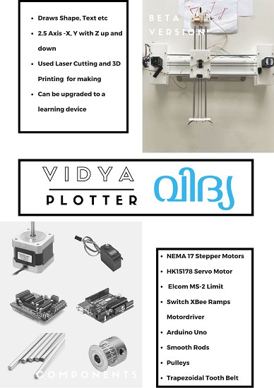
This week's assignment is all about fabricating a machine and its team work. The 5 members of the kochi super fab lab had come up with different ideas for machine week assignment but considering the time constraint and other factors we decided to build a 2.5 Axis CNC Plotter and we named it as ‘ VIDYA’. We split our work to each member and finally with our team work we could demonstrate our machine - VIDYA.
↠ Visit our GROUP PROJECT PAGEfor more details
My Contributions
After preparing the work plan for machine building, myself with Anooj and Nanditha have got the opportunity to design the machine. We chose Auto Desk FUSION 360 as our design platform and w e all have some experience in this designing software. We decided to use Core XY Mechanism for the movements of arms.After a small discussion about the axis of the machine we split design works into 3 modules. I got the opportunity to design X axis arm , anooj designed Y axis and nanditha designed pen holder.
Designing X axis arm of CNC plotter
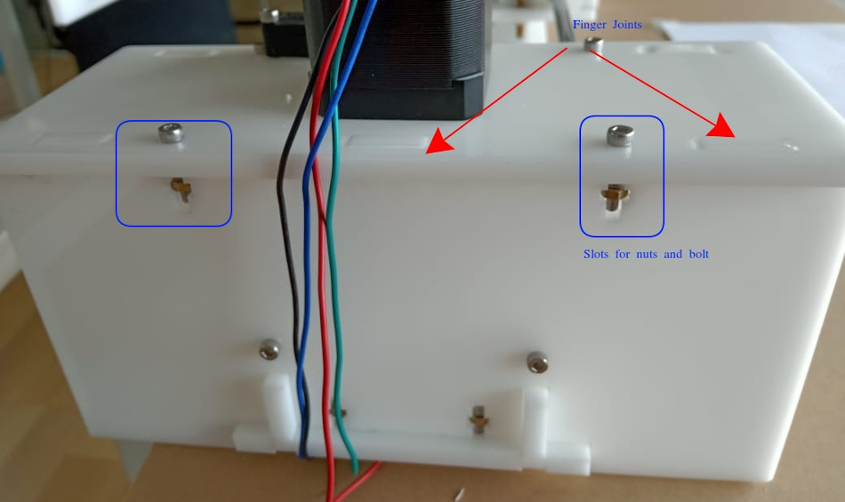
We did parametric designing in fusion 360. My design part consists of two housings for holding two NEMA 17 stepper motors and two 8 mm smooth rods. Components/parts are joined through finger joint mechanism . I also provided slots to accommodate nuts and bolts , this is also for joining parts and hopes it will give more rigidity to the machine. For giving holes for stepper motors I imported nema 17 design file to fusion 360 and did necessary extrusion- cut operation for accommodating motor's shaft from top side.
We used acrylic sheets for fabrication.After completing the design I shared the file with anooj and later we assembled all parts . We used laser cutting machine for making parts from acrylic sheets. And also used 3D printer for printing some critical components
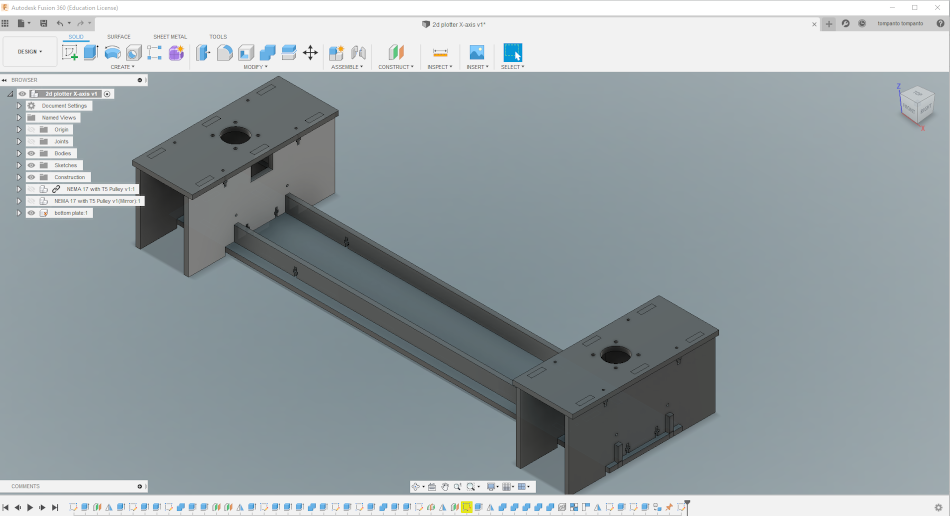
See the X axis arm design below(3 D View)
3D Printing and Laser Cutting
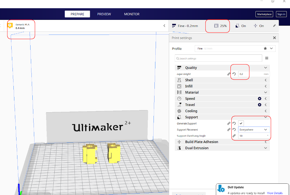
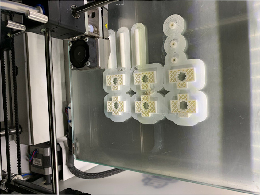
Linear Bearings at the junction of X axis and Y axis arm are designed by Anooj and I 3D printed the bearings.The hole dia of linear bearing is given as 8 mm (dia of smooth rod). After doing some post processing job on linear bearing, we were able to get a desirable fit Settings for 3d priner is shown below. Print settings are 0.4 mm nozzle, 0.2mm layer height etc.
3D printing in progress
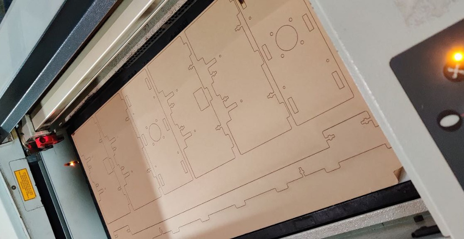
I used a 6 mm acrylic sheet to laser cut the main frame components.A test cutting was done for understanding the Fit and tolerance required for joints. Without giving kerf value we got desired fit for the joints.
Making Video of VIDYA Plotter- Machine Assembly:Working