Week 9: Input devices
Assignment for this week:
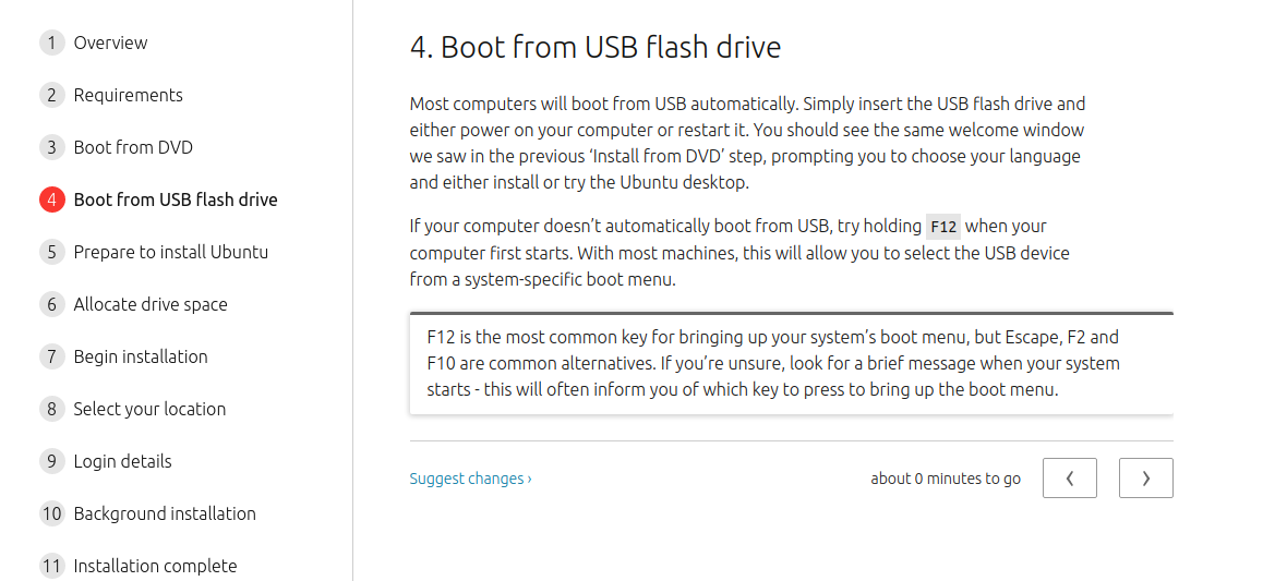
Group assignment: Probe an input device's analog levels and digital signals.
Individual assignment: Measure something: add a sensor to a microcontroller board
that you have designed and read it.
- Introduction
This week I worked with LDR (Light Dependent Resistor) as an input device, did research to see how it works, developed my skills in programming in Arduino IDE and made a circuit which works as a simple light sensor. I chose LDR, because I may use it in one of my final project ideas. I would like to explore color sensors as well, but due to the situation with COVID19 we are in lockdown now and don’t have available color sensors. Hopefully I will have a chance to work with them later during the course.
Besides that, I have learnt about I2C communication protocol and did two small projects on Arduinos using it. Here are some good tutorials and articles, which I used and may be helpful for such beginners as me: Overview: Photocells Arduino tutorial: Master Writer, Slave receiver Arduino Wire library I2C tutorial using two Arduinos I2c using two Arduinos
-
LDR- Light Dependent Resistor
LDR is a Light Dependent Resistor or photoresistor. It is a type of resistor whose resistance varies depending on the amount of light falling on its surface. When the light falls on the resistor, then the resistance changes. A typical light dependent resistor has a resistance in the darkness of 1MOhm, and in the brightness a resistance of a couple of KOhm. This resistor works on the principle of photoconductivity. An LDR or photoresistor is made of any semiconductor material with a high resistance. It has a high resistance because there are very few electrons that are free and able to move - the vast majority of the electrons are locked into the crystal lattice and unable to move. Therefore in this state there is a high LDR resistance. As light falls on the semiconductor, the light photons are absorbed by the semiconductor lattice and some of their energy is transferred to the electrons. This gives some of them sufficient energy to break free from the crystal lattice so that they can then conduct electricity. This results in a lowering of the resistance of the semiconductor and hence the overall LDR resistance.
The rate at which the resistance changes is called the resistance recovery rate. The LDR / photoresists normally responds within a few tens of milliseconds when light is applied after total darkness, but when light is removed it can take up to a second or so for the resistance to reach its final level.
Photoresistors have many different applications..They are widely used in many different items of electronic equipment including photographic light meters, fire or smoke alarms as well as burglar alarms, and they also find uses as lighting controls for street lamps.
- Simple light sensor using LDR
Nowadays most of the lights are operated manually, which brings to the huge waste of electricity. The same time that also brings safety issues, when someone forgets to turn essential lights on. For example, in one of my final project proposals I have mentioned that it’s very important for cyclists to have switched lights on while biking, because usually they are not visible on the streets.
So, in my opinion LDR operated lights are very helpful in both ways: for saving energy when it’s needed and for turning lights on depending on darkness of the environment.
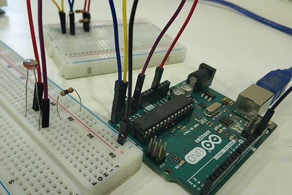
I made a simple light sensor based on LDR. I have 2 LEDs and depended on the lighting outside none, one of them or both are switching on automatically.
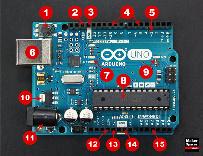
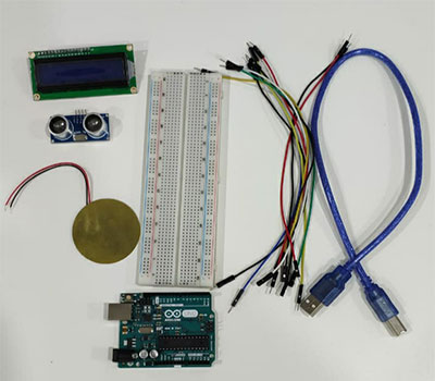
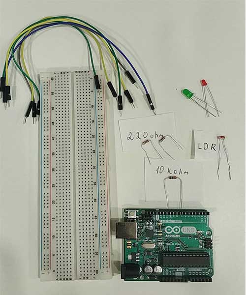
Here are the components which I used for the circuit:- Arduino with the USB cable
- Arduino breadboard
- 2 x LEDs
- 2 x 220ohm resistors
- 6 Male to Male wires
- 10kohm resistor
- LDR
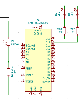
Here are the steps for connecting the components:
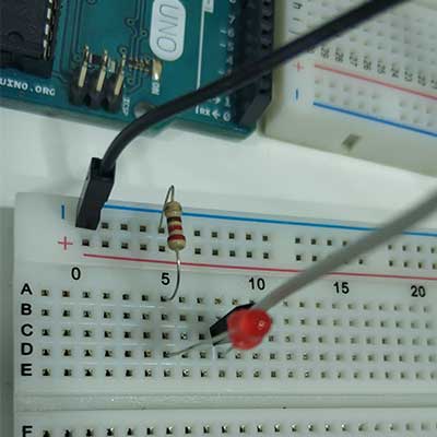
- Attach LED to the breadboard
- Attach 220ohm resistor to the anode (long leg) of the LED
- Attach LED’s cathode (short leg) to the Ground pin on Arduino using a wire
- Attach resistor’s other leg to digital pin 13 on Arduino using a wire
- Repeat this for other LED and 200ohm resistor, connect the second resistor’s leg to digital pin 12 on Arduino using a wire
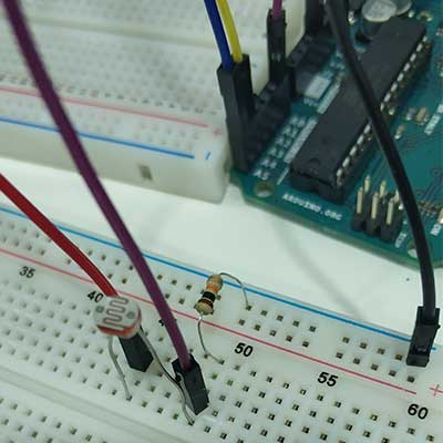
- Attach LDR to the board
- Attach 10 kohm resistor to one leg of the LDR. The resistor with LDR connected in series makes a voltage divider configuration. It’s not easy for microcontrollers (those with analog-to-digital converters - ADC’s - at least) to measure resistance of variable resistors such as LDR. But, by adding another resistor to the resistive sensor, we can create a voltage divider. Once the output of the voltage divider is known, we can go back and calculate the resistance of the sensor.
- Connect the LDR other leg to the Ground pin on Arduino using a wire
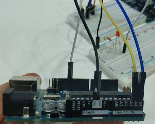
- Connect 10kohm resistor’s other leg to the 5V pin on the Arduino using a wire
- Connect the LDR and 10kohm resistor same column to the A0 pin on the Arduino using a wires
- Connect Arduino to the computer by USB cable
- Upload the following code to the arduino and see the result. When it’s light outside, none of the LEDs will be on. When it’s a bit dark, one of them will turn on automatically, When it’s dark, both of them will turn on.
const int ledPin1 = 13; // setup pin numbers const int ledPin2 = 12; const int ldrPin = A0; void setup() { // put your setup code here, to run once: Serial.begin(9600); pinMode (ledPin1, OUTPUT); // initialize LED1 as an output pinMode (ledPin2, OUTPUT); // initialize LED2 as an output pinMode (ldrPin, INPUT); // initialize LDR as an input } void loop() { // put your main code here, to run repeatedly: int ldrStatus = analogRead (ldrPin); // read LDR value if (ldrStatus >=500) { // if the value is higher than 500, both LEDs are off digitalWrite (ledPin1, LOW); digitalWrite (ledPin2, LOW); Serial.println("it's bright"); } else if (ldrStatus < 300) { // if the value is lower than 300, both LEDs is on digitalWrite (ledPin1, HIGH); digitalWrite (ledPin2, HIGH); Serial.println("it's too dark"); } else { // if the value is lower than 500 but higher than 300, one of the LEDs is on digitalWrite (ledPin2, HIGH); digitalWrite (ledPin1, LOW); Serial.println("it's dark"); } Serial.print(ldrStatus); // print LDR value with 500ms delay delay(500); } - When the board is programmed, you can turn the USB cable off and use other sources to power the Arduino. I used a 9V battery with a battery connector. Just attach the battery to the connector and connect it’s positive terminal to the VIN of Arduino and the negative terminal to the ground of Arduino.
Here is the result.
The original file with the code: Light sensor using LDR, code
The original file with the schematic: Light sensor using LDR, schematic - I2C communication protocol and Arduino Wire library
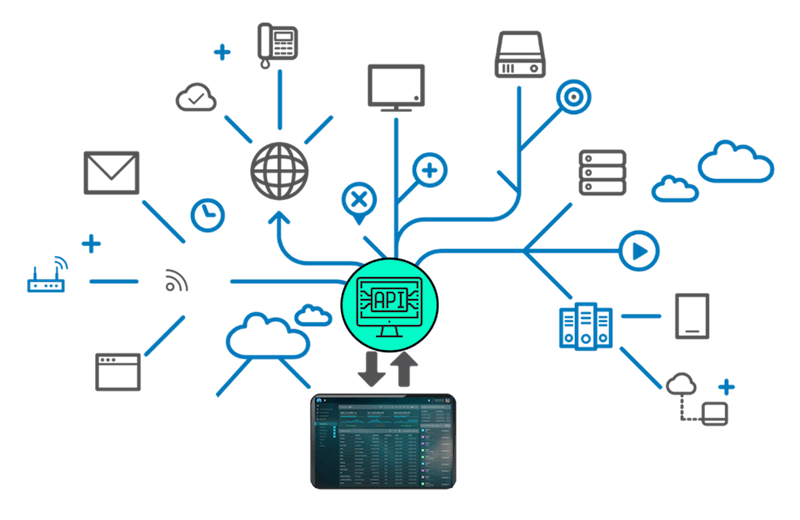
Sometimes we have to use more than one Arduinos or other boards to share information with each other. For that we use some communication protocols: a set of rules and regulations that allow two electronic devices to connect to exchange the data with one and another. There are many microcontroller communication protocols and one of them is I2C communication protocol.
I²C (Inter-Integrated Circuit) protocol is a serial protocol for two-wire interface to connect low-speed devices like microcontrollers. It is used with microcontrollers like the Arduino and with microcomputers like the Raspberry Pi . Many displays and sensors interface to their host controller using I2C.
I2C does have several limitations however. It is not particularly fast, it can only be used over short distances. I2C and has some higher speed modes (up to clock frequency of 5 MHz). Not all I2C devices support these modes. The maximum distance of reliable transmission decreases as the speed increases, at the slowest speed (100 Kbaud or a clock rate of 100 KHz) the maximum distance is about a metre.
An I2C bus has two signals, along with a power and ground connection: SDL (Serial Digital Line) and SCL (Serial Clock Line).
There are two types of devices that can be interfaced to the I2C bus – Masters and Slaves.
The Master device controls the bus and supplies the clock signal. It requests data from the slaves individually. There can be more than one master device on the bus but only one can be the active master at any given moment.
The master devices do not have an address assigned to them.
Slave devices do have an address, and this address needs to be unique on the bus. They use a 7-bit addressing scheme, so up to 128 slaves can be on one I2C bus. In real life this large collection of devices is never used, it is rare to see over a dozen I2C devices on one bus.The Arduino has a built-in library for working with I2C called the Wire Library. It makes it very easy to communicate on the I2C bus, and it can configure the Arduino to become either a master or a slave. The Wire library has several useful functions for working with I2C.
- begin() –This initiates the library and sets up the Arduino to be either master or slave.
- requestFrom() –This function is used by the master to request data from a slave.
- beginTransmission() – This function is used by the master to send data to a specified slave.
- endTransmission() – This function is used by the master to end a transmission started with the beginTransmission function.
- write() –Used by both master and slave to send data on the I2C bus.
- available() – Used by both master and slave to determine the number of bytes in the data they are receiving.
- read() –Reads a byte of data from the I2C bus.
- SetClock() –Used by the master to set a specific clock frequency.
- onReceive() – Used by the slave to specify a function that is called when data is received from the master.
- onRequest() – Used by the slave to specify a function that is called when the master has requested data.
-
I2C communication between two Arduinos (Master Writer - Slave Receiver )
First thing which I tried was an Example from the Arduino Wire library: Master Writer - Slave Receiver. In this case we have one master and one slave board. Master sends numbers which are being received by the slave. There is no action back required from the slave device. I did this just to establish and send communication, get used to the new library and concepts for me.
For this project I used:- 2 x Arduino Uno boards with USB cables
- Arduino breadboard
- 2 x 10kohm resistors
- 7 x male to male wires
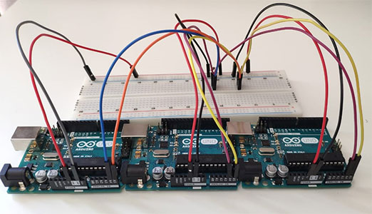
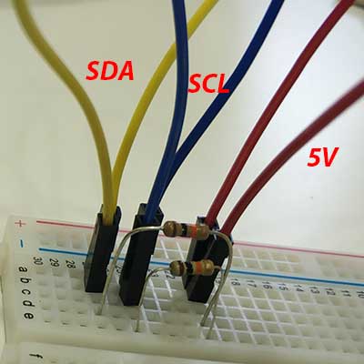
Here is the steps for communication and the schematic: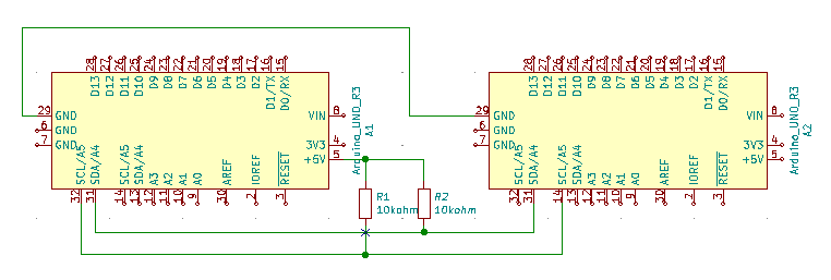
- Connect SDA lines (yellow wires on the image) of both Arduinos and a 10kohm resistor on the same line with them.
- Connect SCL (blue wires on the image)lines of both Arduinos and a 10kohm resistor on the same line with them.
- Connect the other legs of both 10kohm resistors to the 5V pin of one of the Arduinos (red wire on the image).
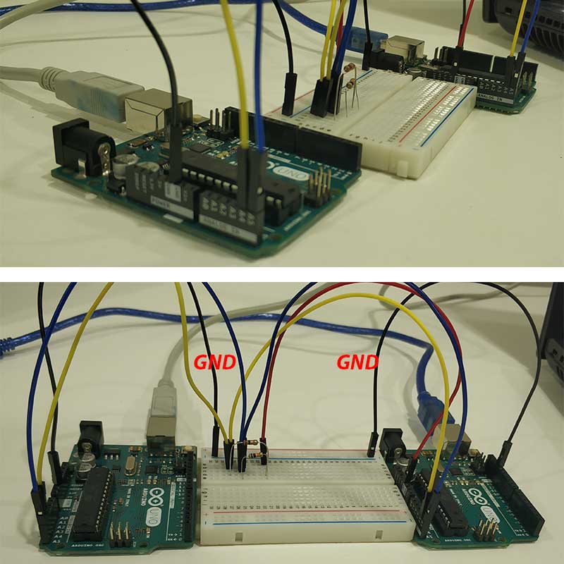
- Connect Ground pins of both Arduinos together (I did this using the negative rail of the breadboard as a common ground, black wires on the image).
When connections were done, I connected Arduinos to two different computers and ran the following codes for master and slave devices on them . You can find these codes in File → Examples → Wire → Master Writer and Slave receiver accordingly for each board.
Wire Master Writer// Wire Master Writer // by Nicholas Zambetti
Wire Slave Receiver// Wire Slave Receiver // by Nicholas Zambetti
And here is the result which I could see on the Serial monitor for the slave device.The file with the code for Master: Master Writer
The file with the code for Slave: Slave receiver
The original file with the schematic: Light sensor using LDR, schematic -
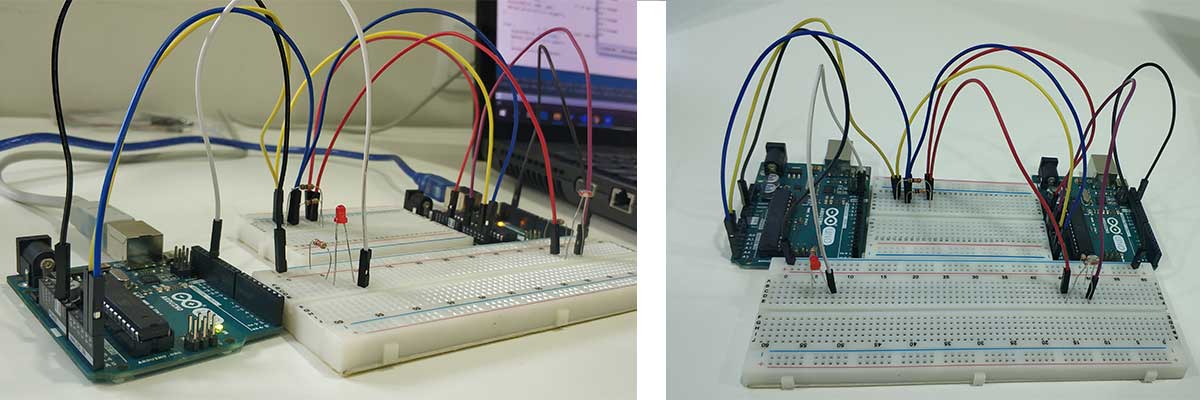
LED control depended on light using LDR and I2C communication protocol
After being more confident with working with two Arduinos, I run the same project - LDR controlled LED, this time using two boards. One of them is master, LDR is connected to that and the received data from it is being mapped from 1-255 and passed to the slave board. The LED is connected to the slave device. When the slave receives the data from the master, the data is being mapped again to have the actual reading from the LDR and depending on that program checks if the LED should be on or off.
Components used for this project:- 2x Arduino Uno boards with USB cables
- 2x Arduino breadboards
- 3x 10kohm resistors
- 220 ohm resistor
- LED
- LDR
- 10x male to male wires
Here are the steps for connections and the schematic:
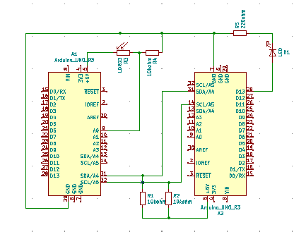
- Establish I2C connections between two Arduinos as it was described in the previous section.
- Connect both Arduinos’ Ground pins to the same negative rail of the second breadboard using wires. By doing this we establish a common Ground between both Arduinos and for other components.
- Attach one leg of the 10kohm resistor to the same negative rail. Resistor should be attached vertically.
- Attach LDR horizontally, one leg of it should be on the same column as resistors’s free leg.
- Connect LDR’s other leg to the 5V line on the first breadboard.
- Connect 10kohm resistor’s and LDR’s common column to the A0 pin of the master Arduino board using a wire.
- On the other side of the same breadboard we will connect LED. First of all attach 220ohm resistor’s one leg to the negative rail.
- Attach the LED’s short leg to the 220ohm resistor’s other leg
- Connect LED’s long leg to the Digital pin 13 of the Arduino board using a wire.
// Master with LDR
// Include Arduino Wire library for I2C
#include Wire.h

// Define Slave I2C Address
#define SLAVE_ADDR 9

// Analog pin for ldr
int analogPin = 0;
// Integer to hold ldr value
int val = 0;

void setup() {

  // Initialize I2C communications as Master
  Wire.begin();
}

void loop() {
  delay(50);

  // Read ldr value
  // minimum and maximum values for ldr are 0 - 1023
  // Map to range of 1-255 for passing to slave
	val = map(analogRead(analogPin), 0, 1023, 1, 255);

  // Write a character to the Slave
  Wire.beginTransmission(SLAVE_ADDR);
  Wire.write(val);
  Wire.endTransmission();
}
Slave with LCD// Slave with LCD // Include Arduino Wire library for I2C #include Wire.h // Define Slave I2C Address #define SLAVE_ADDR 9 // Define LED Pin int LED = 13; // Variable for received data int rd; // Variable for ldr status int ldrStatus; void setup() { pinMode(LED, OUTPUT); // Initialize I2C communications as Slave Wire.begin(SLAVE_ADDR); // Function to run when data received from master Wire.onReceive(receiveEvent); // Setup Serial Monitor Serial.begin(9600); } void receiveEvent() { // read one character from the I2C rd = Wire.read(); } void loop() { delay(50); // Calculate ldr value ldrStatus = map(rd, 1, 255, 0, 1023); if (ldrStatus >=300) { // if the value is higher than 300, LEDs is off digitalWrite (LED, LOW); Serial.println("it's bright"); } else { // if the value is lower than 300, LEDs is on digitalWrite (LED, HIGH); Serial.println("it's dark"); } Serial.println(ldrStatus); }As a result I got this simple light sensor
The file with the code for Master: Master With LDR
The file with the code for Slave: Slave With LED
The original file with the schematic: Light sensor using LDR, schematic with 2 Arduinos -
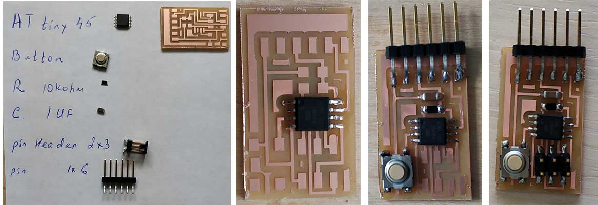
Hello.button.45
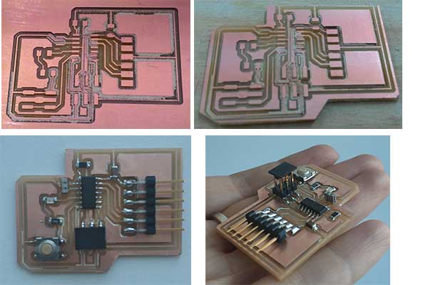
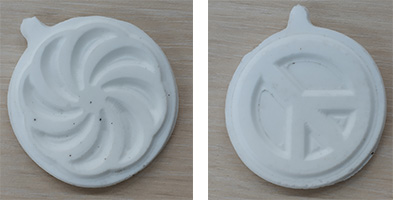
When we were out of quarantine, I started to do missed assignments from electronics. As we didn’t have much time, we were allowed to cut one of Neil's boards rather than design our own ones. I have decided to make the hello button45 board because I’m going to have a button on my final project and it would be nice to have experience beforehand.
First of all I downloaded images for traces and interior of the board and generated G codes in fabmodules.org.

Then I did milling the board and started assembling it.
To do the programming I need to connect the board to fab ISP using a USB cable and to the computer, using a FTDI cable.
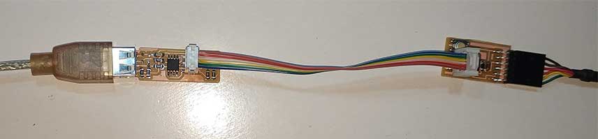
Then download C code and make file from the keynotes. Also, as I’m going to use the serial monitor, I need the term.py file.
After downloading them and locating in one folder, I started programming by running the following codes:
make -f hello.button.45.make
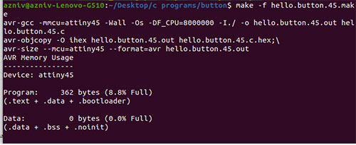
make -f hello.button.45.make program-usbtiny
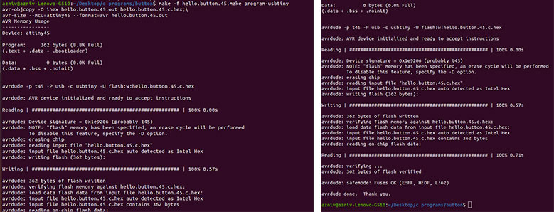
If everything goes well we should open the serial monitor by running the command
python term.py /dev/ttyUSB0 9600
Here ttyUSB0 is the port where your FTDI cable is connected to and 9600 is the serial monitor baud. This should be the same as in the C code.
I had a problem with running the serial monitor and was constantly getting an error that tkinter file can not be imported. I found good documentation from a previous year’s student Nicolo Gnecci where the similar problem was described and solved. I have tried almost everything but it didn’t work again.
Then I found the issue described in Stackoverflow and found out that in the Python code there is a line which should be different depending on your Python version. It says that the Tkinter module is named Tkinter (capital "T") in python 2.x, and tkinter (lowercase "t") in python 3.x.
As I have python 2, I just changed the lowercase “t” to uppercase in the code and it worked.
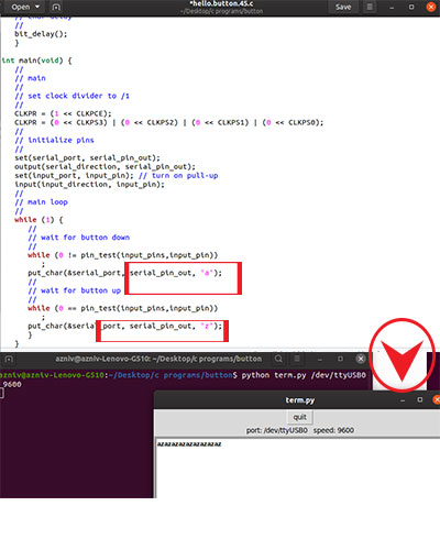
Basically, it types letter “b” on the serial monitor, when button is pressed and letter “u”, when button is being released. I found that part of the code and changed the letters to “a” and “z”.
-
Input devices in final project
For my final project I have used a limit switch and an LDR as input devices. Both of them were used as an indicator for LEDs as output device to be on or off
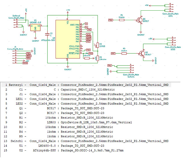
Further down you can see the components used for my board, the schematic and the board itself.I did the design of the board in KiCAD.
Here is the list of components:- ATtiny44 microcontroller
- 5V voltage regulator
- 2* 10kOhm resistors ( 1 for microcontroller and 1 for LDR)
- 1uF capacitor
- LDR
- 2* BC817 transistors
- 2* 1kOhm resistors to attach to the transistors
- A connector header to connect the switch from the brakes
- A connector header to connect the battery
- Two connector headers for LEDs
- 2*3 connector header to connect the programmer
I added all of the components from the KiCad library and started to connect them.
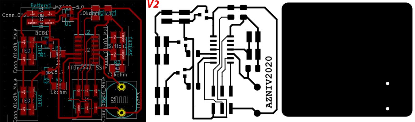
Then I designed the PCB, exported it as svg and cut the board as it’s described in Electronics production and electronics design weeks. I checked all of the connections by the digital multimeter, seems everything is fine.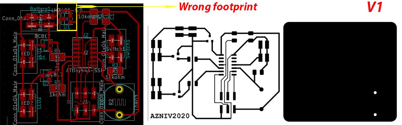
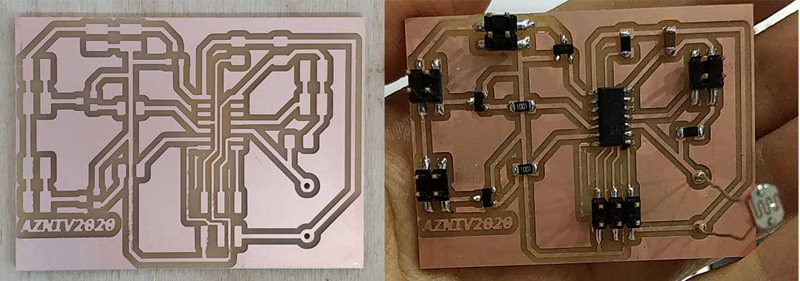
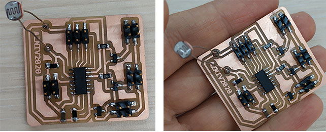
Programming was successful but the board didn’t work. Then I started to check the connections again, all was fine. Afterwards I have checked the footprints and found out that I have a wrong footprint and connections for the voltage regulator. So I have changed the footprint and connections to the proper ones. This time I moved the components closer to each other and my board got smaller.
After assembling the board, I did the programming and this time it worked, hooray.
-
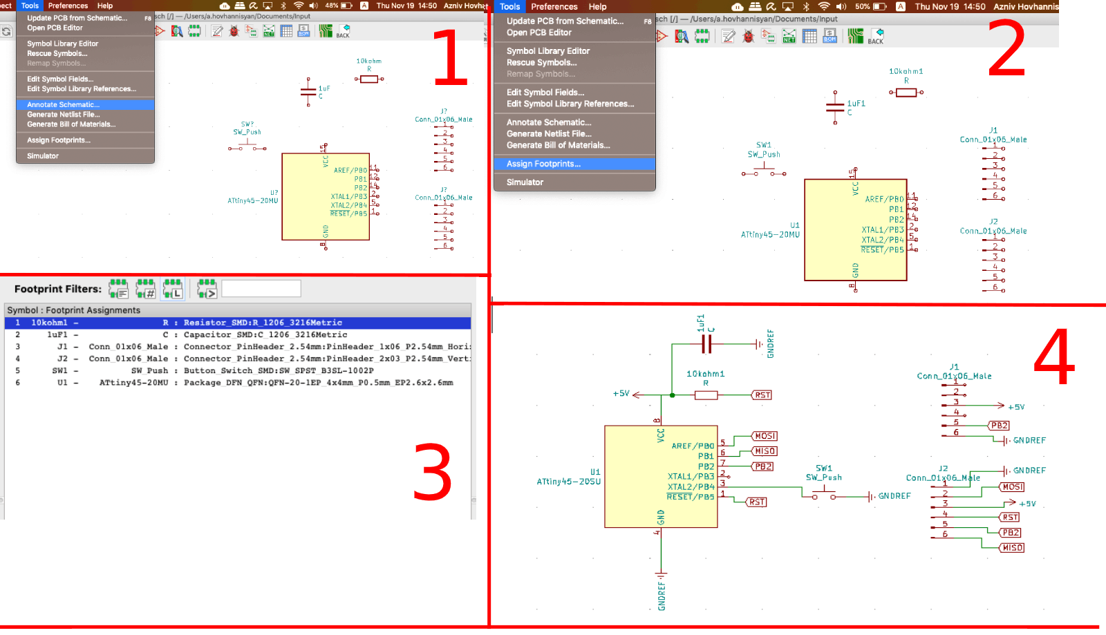
Designing hello.button.45 in KiCad
I don't have chance for fabricating the board as lab is closed due to the pandemic, I was asked to design a board with an input device. I have decided to design one similar to hello.board.45. For that:- I have opened KiCAD and opened a New project
- In schematic sheet I chose the components that I need:
- ATtiny45 microcontroller
- Connector headers, 1*6 and 2*3
- Capacitor, 1uF
- Resistanor, 10kohm
- Switch button
- After chossing the components I have annotated the schematic and assigned the footprints for them
- Then I have done the connections using the wiring tool. To not make my schematic look like a spider web, I have used global label tool and labeled some of the pins with the same name. In that case program assumes that pins are connected.
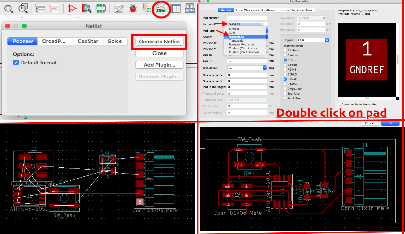
- When connections are done, I generated netlist
- Import that netlist to the PCB bart of the KiCad
- Some pads wer not correctly labeled on the schematic part. To change this double click on the pad and change the footprint type as well ase the label
- Using the wiriing tool do the connections
- Using the edge cut tool draw the edges
- Export the pcb as svg
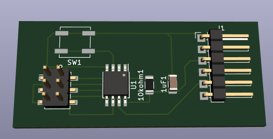
- Go to View ⇛ 3D view to see how will the PCB look like
-
Conclusion
This week was full of different emotions and outcomes: research, more research, reading, trying, failing, research again and the success in the end. I started to pay attention to very small details, which I haven’t quite done before, learnt about input devices, I2C connection protocol and it’s usage and did more practical work. I do understand that everything I have learnt is a very small part of the input devices and there is still more to explore and learn. So during the next weeks I’m going to develop these skills and add more to them.
After the quarantine I have cut, assembled and programmed hello.button.45 board. It was a good experience for me in the sense of programming using C codes, which is completely new for me. -
Files
hello.button.45 programming files
hello.button.45 traces and interior
hello.button.45 original design files
Light sensor using LDR, code
Light sensor using LDR, schematicMaster With LDR
Slave With LED
Light sensor using LDR, schematic with 2 Arduinos