Week 14: Networking and communications
Assignment for this week:
Individual assignment: Design, build, and connect wired or wireless node(s)
with network or bus addresses
Group assignment: Send a message between two projects
- Introduction
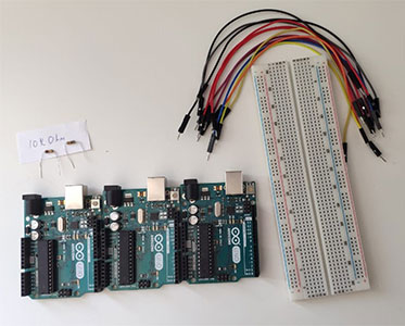
This week I had to design, build, and connect wired or wireless node(s) with network or bus addresses. I did networking using I2C protocol during the Input devices week and connected 2 Arduinos. This week I had a challenge to explore other types of networking and do something new, so I decided to connect three Arduinos. In this article I found very detailed information about the types of communication protocols and how they work. And here I could see the comparison of Serial protocols. Even though I have already done I2C bus communication before, it was challenging with three Arduinos.
Useful articles and tutorials: - Three Arduinos talking with I2C
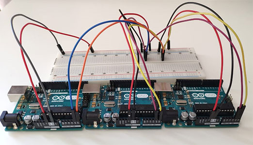
I have explained the working principles of I2C protocol earlier in Input devices week. This week I used the same principles for three Arduinos. First of all I wanted to check with pre-existing code if my connections are correct and everything is working. I followed instructions from this video to establish a basic connection between three arduinos having one master and two slaves. The program is very simple - as soon as the master starts the wire transmission,, built-in LEDs of the slave Arduinos will turn on in turns.
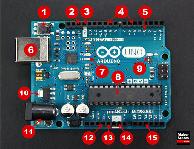
As I had troubles in my previous project I had problems with serial communication without pull-up resistors, this time I have added pull-up resistors from the very beginning. So for this project we need:- 3 Arduino Unos
- A breadboard
- 2 10kOhm resistors
- 12 male to male wires
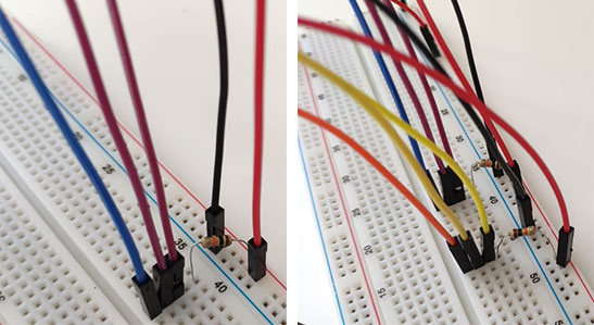
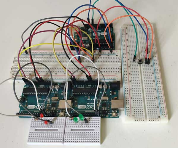
Connection of the components: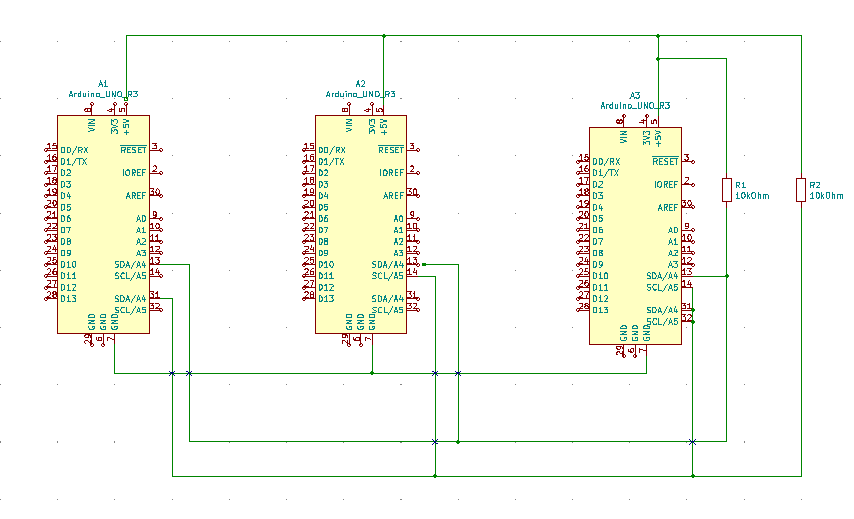
- Connect the Ground pins of all Arduinos to one of the negative rails on the breadboard. This way will establish a common Ground for them all.
- Connect the 5V pins of all Arduinos to one of the positive rails on the breadboard. This way will establish a common Power for them all.
- Connect the SDA (A4) pins of all Arduinos to the same column on the breadboard. Then connect the column to the positive rail via 10kOhm pull-up resistor.
- Connect the SCL (A5) pins of all Arduinos to the same column on the breadboard. Then connect the column to the positive rail via 10kOhm pull-up resistor.
I downloaded the codes for master and slave devices and uploaded to the boards.
#include < Wire.h>

void setup()
{
  Wire.begin();
}

void loop()
{
  Wire.beginTransmission(1);
  Wire.write('H');
  Wire.endTransmission();

  delay(500);

  Wire.beginTransmission(1);
  Wire.write('L');
  Wire.endTransmission();

  delay(500);

  Wire.beginTransmission(2);
  Wire.write('H');
  Wire.endTransmission();

  delay(500);

  Wire.beginTransmission(2);
  Wire.write('L');
  Wire.endTransmission();

  delay(500);
}
#include < Wire.h> const byte slaveId = 1; // pute here your slave Id void setup() { Wire.begin(slaveId); Wire.onReceive(receiveEvent); pinMode(13,OUTPUT); digitalWrite(13,LOW); } void loop() { } void receiveEvent(int howMany) { char inChar; while(Wire.available() > 0) { inChar = Wire.read(); if (inChar == 'H') { digitalWrite(13, HIGH); } else if (inChar == 'L') { digitalWrite(13, LOW); } } }And the video with the result:
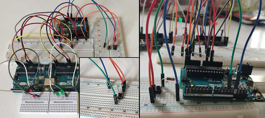
- Controlling the LEDs by push button using I2C protocol
In this project I have connected a push button to the master Arduino and LEDs to the slave Arduinos. When the button is pressed, the master requests the LED state from slaves and changes it to the opposite. So if the LED is on, it will turn off and the opposite. I programmed them in a way that if the one set of lights is on, the other one is off. Also, to make the setup more attractive I programmed the lights to blink instead of being constantly on.
Here is the list of components: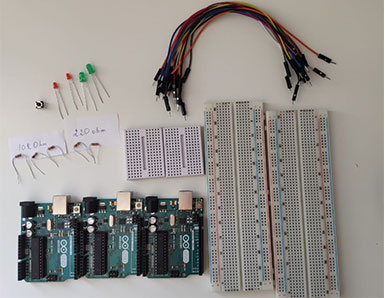
- 3* Arduino Unos
- 4* breadboard
- 3* 10kOhm resistors
- 2* 220Ohm resistors
- 4* LEDs
- 1* pushbutton
- 14* male to male wires
Connections for LEDs and push button are done the same way as in Embedded programming week. And the I2C connections are the same as in the previous example.
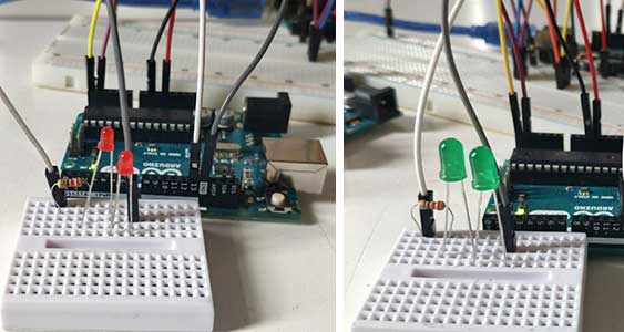
- Connect LED on one of the horizontal lines of the breadboard.
- Connect 220 ohm resistor to the LED’s long leg (anode +).
- Connect the resistor’s other leg to the digital pin 13 on Arduino using a wire.
- Connect another LED to the first one.
- Connect the second LED’s short (cathode -) leg to the Ground on Arduino using a wire.
- Repeat the same for the other couple of LEDs and second Arduino.
- Attach button to the board
- Connect the 10kohm resistor to the button's bottom leg. Connect the 10 kom resistor’s other leg to the Ground on master Arduino using a wire.Connect button’s other bottom leg to to the 5V on Arduino using a wire.
- Connect button’s top leg to the digital pin 12 on Master Arduino using a wire.
Now upload the following codes for master and slave devices accordingly.
Code for the Master device
#include < Wire.h>

	int receivedValue = 0;
	int LEDPin = 13;
	int buttonPin = 12;
	int isSelected = false;
	int buttonState = 0;

	void setup() {
	  // Start the I2C Bus as Master
	  Wire.begin();
	  Serial.begin(9600);

	  //Set pin modes for the led and button pins
	  pinMode(LEDPin, OUTPUT);
	  pinMode(buttonPin, INPUT);
	}

	void loop() {

	  //Request 1 byte from Arduino at address 9
	  Wire.requestFrom(9, 1);

	  while (Wire.available()) { // slave may send less than requested
		receivedValue = Wire.read(); // receive a byte as int
		Serial.println(receivedValue);         // print the int
	  }

	  //Read in button state and see if it is high
	  buttonState = digitalRead(buttonPin);
	  Serial.println(buttonState);
	  if(buttonState == HIGH){
		isSelected = !isSelected;
		delay(500);
	  }


	   //Begin transmission and send isSelected.
	  Wire.beginTransmission(8); // transmit to device #8
	  Wire.write(isSelected);              // sends x
	  Wire.endTransmission();    // stop transmitting
	  delay(100);

	  //Begin transmission and send isSelected.
	  Wire.beginTransmission(9); // transmit to device #9
	  Wire.write(isSelected);              // sends x
	  Wire.endTransmission();    // stop transmitting
	  delay(100);
	}
Code for the Slave 1 device
#include < Wire.h>

int LED = 13;
bool valueReceived;
int isOn = 0; // Off = 0 On = 1

void setup() {
  //Set up serial output baud number
  Serial.begin(9600);
  // Define the LED pin as Output
  pinMode (LED, OUTPUT);
  // Start the I2C Bus as Slave on address 9
  Wire.begin(9);
  // Attach a function to trigger when something is received.
  Wire.onReceive(receiveEvent);
  //Attach a function to trigger when something is requested
  Wire.onRequest(requestEvent);
}

void receiveEvent(bool bytes) {
  //Read one value from the I2C
  valueReceived = Wire.read();
  //Display the value received
  Serial.println(valueReceived);
  //If the value received was true turn the led on, otherwise turn it off
  if(valueReceived){
    isOn = 1;
  }
  else{
    isOn = 0;
  }
}

void requestEvent(){
  //Tell the master whether the led is on or not
  Wire.write(isOn);
}

void loop() {
  //Turn on or off the led based on the master's input
  if(isOn){
	// make LED to blink
    digitalWrite(LED, HIGH);
    delay(200);
    digitalWrite(LED, LOW);
    delay(200);
  }
  else{
    digitalWrite(LED, LOW);
  }
}
Code for the Slave 2 device
#include < Wire.h>

int LED = 13;
bool valueReceived;
int isOn = 0; // Off = 0 On = 1

void setup() {
  //Set up serial output baud number
  Serial.begin(9600);
  // Define the LED pin as Output
  pinMode (LED, OUTPUT);
  // Start the I2C Bus as Slave on address 1
  Wire.begin(8);
  // Attach a function to trigger when something is received.
  Wire.onReceive(receiveEvent);
  //Attach a function to trigger when something is requested
  Wire.onRequest(requestEvent);
}

void receiveEvent(bool bytes) {
  //Read one value from the I2C
  valueReceived = Wire.read();
  //Display the value received
  Serial.println(valueReceived);
  //If the value received was true turn the led on, otherwise turn it off
  if(valueReceived){
    isOn = 1;
  }
  else{
    isOn = 0;
  }
}

void requestEvent(){
  //Tell the master whether the led is on or not
  Wire.write(isOn);
}

void loop() {
  //Turn on or off the led based on the master's input
  if(isOn){
    digitalWrite(LED, LOW);
  }
  else{
    digitalWrite(LED, HIGH);
    delay(200);
    digitalWrite(LED, LOW);
    delay(200);
  }
}
And the video with the result:
When we were back to lab, I deided to make and program the
serial bus boards from the
Networking and communications week.
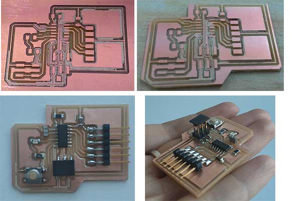
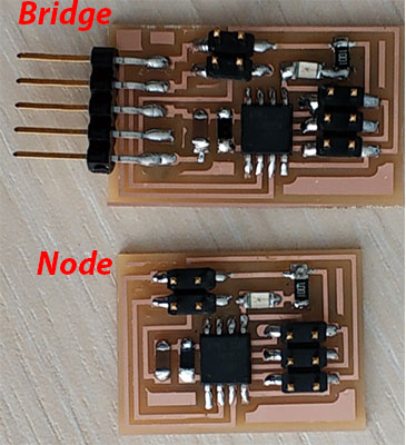
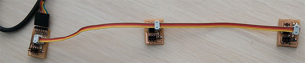
To have a clear idea how does it work, I need to hve at least one bridge and two node boards. As we had a node board in the lab from the last year, I made one bridge and one node.
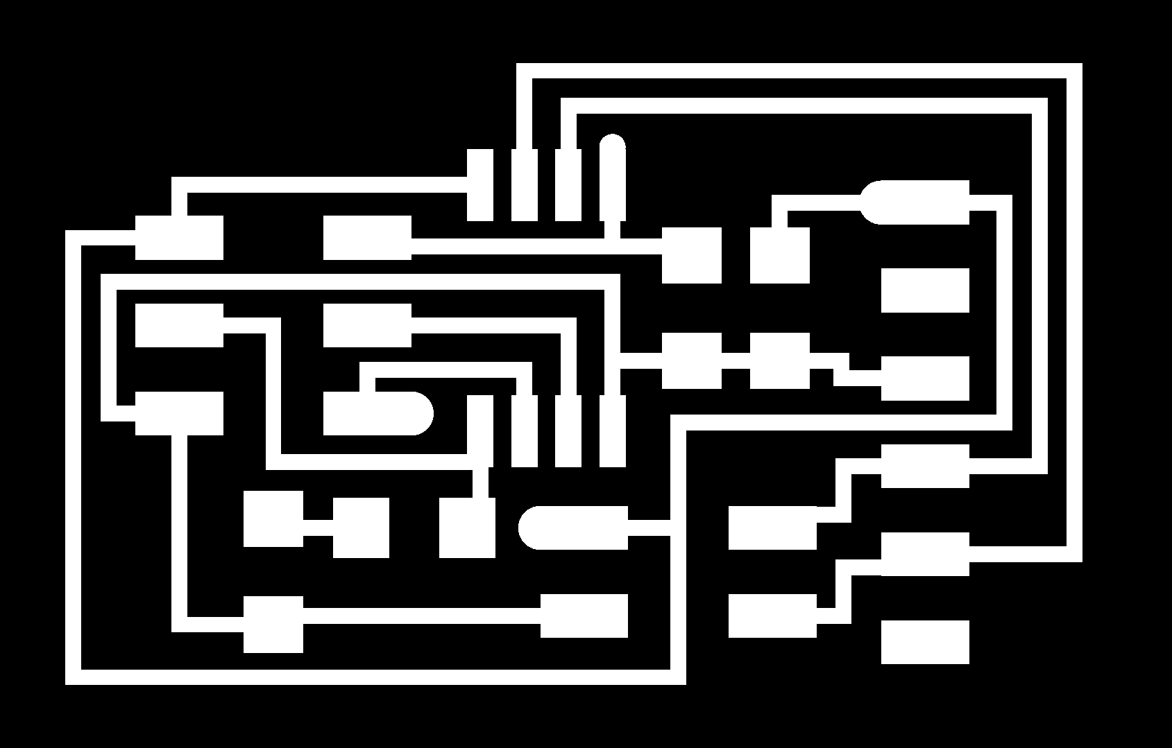
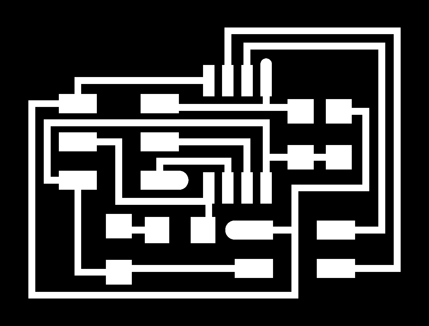
First of all I downloaded images for
traces and
interior of the bridge and
traces and
interior of the node
and generated G codes in
fabmodules.org.


Then I did milling the board and started assembling it.
To do the programming I need to first of all connect the bridge board to fab ISP using a USB cable and to the computer, using a FTDI cable.
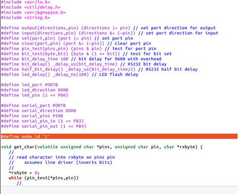
Then download
C code and
make file from the
keynotes.
Also, as I’m going to use the serial monitor, I need the
term.py file.
Here is the tutorial for the programming the boards.
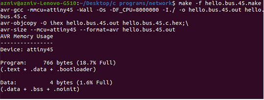
After downloading them and locating in one folder, I started programming by running the following codes:
make -f hello.bus.45.make
make -f hello.bus.45.make program-usbtiny
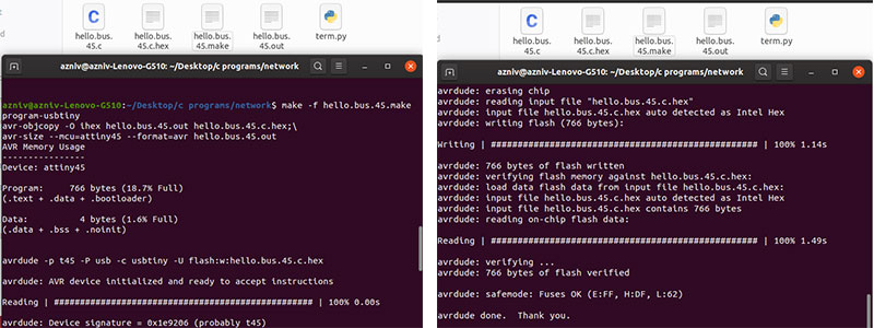
Now we have to connect a node to the bridge using a pin header connector wire and connect the ISP to the node as well. In the C code there is a line for defining the node number. We have to change that number for each node to identify them. So I have changed 0 to 1 and programmed the node board running the same command:
make -f hello.bus.45.make program-usbtiny
Do the same for all of the nodes, connect them using the connector wire and then open the serial monitor by running the command
python term.py /dev/ttyUSB0 9600
Now if we press any number of the nodes in the keyboard the LEDs on all of the nodes will blink but we will get the response on serial monitor from the particular node only.
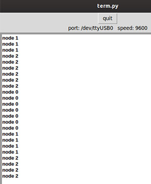
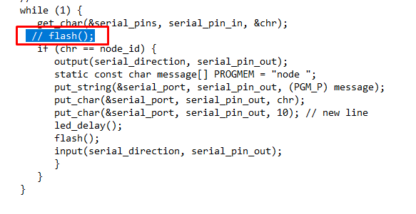
I changed a part of the code and commented the line, where it says to flash thelight when any key is pressed. In this case the LED will be flashing only when the number of it's node is pressed on the keyboard.
Before this week I didn’t have a chance to explore types of communication protocols except for I2C. This week I have learned about the other types, differences between Serial and Parallel communication protocols as well as the differences between different types of serial communication protocols.
I did a project to connect three Arduinos by I2C communication protocol, which eventually worked very well. During the process I had different issues mainly with connections and I had to run different example programs from Arduino IDE to check if different parts of projects are working properly. For example, I have used Blink to check the LED connections and the program from my embedded programming week to check the button connections, etc. I could use the serial monitor instead but that would be more complicated.
To put in a nutshell, this was a productive week with research, learning, trials and the result.
I am going to improve this mode and include it in my final project . I will have a master and several slave devices there, receiving commands from master and sending back their status.
Three Arduinos talking with I2C, Master
Three Arduinos talking with I2C, Slave
LED control by button, Master
LED control by button, Slave 1
LED control by button, Slave 2
hello.bus.45 programming files
hello.bus.45 traces, interior and G codes