Week 17: Mechanical design, machine design
Assignment for this week:
Group assignment:
- design a machine that includes mechanism+actuation+automation
- build the mechanical parts and operate it manually
- document the group project and your individual contribution
- Introduction
This week we had to design a machine that includes mechanism+actuation+automation in a group. It was hard to come up with an idea but we have decided to design and make a machine, which bands plexiglass.
I was doing the electronic part, programming and we all together did assembling. Before starting I was thinking that everything will be very simple and easy, but actually I spent quite a lot of time learning about DC motors, Arduino motor shields and how they work and operate.
This was a very good learning experience, as I was not interested in motors and would never choose to work with them by myself and now I had to work and learn their principles.
Besides this, I have designed and made an Arduino shield to connect all the components that we use for the machine to the motor shield in a nice and compact way.
It was a bit hard for us to work in a group, because we have different schedules, but we did our best to have some online brainstorming discussions and find a common time to work in the lab.
As we didn’t have a group website yet, I developed one on HTML5 template and pushed to the group repository. Now we have a group website, where will be uploaded all of our group assignments. The full workflow for this week is in our group website -
The machine
As I have mentioned in the introduction, after some discussions we have decided to design and make a plexiglass folding machine. The idea came after watching the following video.
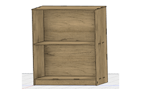
Here the banding is happening mechanically, we decided to make this process automatized. So we will have a wooden table-base and two other pieces of the wood connected together. In the middle there will be a hot wire, which will heat the plexiglass and help us to band it. One is static and the second one will be lifted using a DC motor. We will set up the angle manually and will have a protractor to set the desired angle properly.
We will use limit switches, to detect that the dynamic plane reached its destination points and a push button, to start the process. Basically, when we press the start push button, the machine will start working, if it’s in the start position(it will be detected by the first limit switch). When the dynamic plane reaches the desired angle (it will be detected by the second limit switch), the motor will stop for a while and start rotating to the opposite direction bringing the plane to the start position. This is the minimum that the machine requires but we were thinking that it would be nice to have a sound signal as well and an LED screen for some feedback from the machine.
After having the model sketch, we have divided the work in the following way:- Ashot is doing design and CNC cut of some wooden parts
- I am doing the electronics and programming part
- Joseph is doing the worm-gear mechanism and protractor
- We all are doing assembling testing and troubleshooting, fixing and testing again
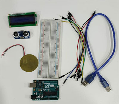
- Understanding the components
DC motorBecause the key component in this circuit is the DC motor, the first challenge for me was driving the DC motor using the Arduino motor shield and getting to know all of the details about it.
Here are some tutorials which I found informative:- Arduino Motor Shield Tutorial
- Arduino Motor Shield Tutorial, All About Circuits
- Arduino L293D Motor Driver Shield Tutorial
- Controlling DC Motors with the L298N Dual H-Bridge and an Arduino
Basically, it says :- Motors are an inseparable part of many robotics and electronics projects and have different types you can use depending on their application. Here is some information about different types of the motors:
- DC Motors: DC motor is the most common type of engine that can be used for many applications. We can see it in remote control cars, robots, and etc. This motor has a simple structure. It will start rolling by applying proper voltage to its ends and change its direction by switching voltage polarity. DC motors speed is directly controlled by the applied voltage. When The voltage level is less than the maximum tolerable voltage, the speed would decrease.
- Stepper Motors: In some projects such as 3D printers, scanners and CNC machines we need to know motor spin steps accurately. In these cases, we use Stepper motors. Stepper motor is an electric motor that divides a full rotation into a number of equal steps. The amount of rotation per step is determined by the motor structure. These motors have a very high accuracy.
- Servo Motors: Servo motor is a simple DC motor with a position control service. By using a servo you will be able to control the amount of shafts rotation and move it to a specific position. They usually have a small dimension and are the best choice for robotic arms.
In a simple DC motor there are two main components, the “stator” and the “armature”. The stator is a permanent magnet and provides a constant magnetic field. The armature, which is the rotating part, is a simple coil.
The armature is connected to a DC power source using a 2-piece ring installed around the motor shaft, these ring sections are called “commutator rings”. The two pieces of the commutator rings are connected to each end of the armature coil. Direct Current of a suitable voltage is applied to the commutator rings via two “brushes” that rub against the rings.
When DC is applied to the commutator rings it flows through the armature coil, producing a magnetic field. This field is attracted to the stator magnet (remember, opposite magnetic polarities attract, similar ones repel) and the motor shaft begins to spin.
The motor shaft rotates until it arrives at the junction between the two halves of the commutator. At that point the brushes come into contact with the other half of the commutator rings, reversing the polarity of the armature coil (or coils, most modern DC motors have several). This is great because at this point the motor shaft has rotated 180 degrees and the magnetic field polarities need to be reversed for the motor to continue rotating. This process repeats itself indefinitely until the current is removed from the armature coils. (image credits https://dronebotworkshop.com/dc-motors-l298n-h-bridge/)
Better quality DC motors are the brushless variety. Brushless motors use a more complex arrangement of coils and do not require a commutator. The moving part of the motor is connected to the permanent magnet. Because they do not contain brushes these brushless motors will last longer and are also much quieter than brushed DC motors. Most quadcopter Motors are brushless motors.
To reverse the direction in which the DC motor rotates you simply reverse the polarity of the DC current that you apply to it.
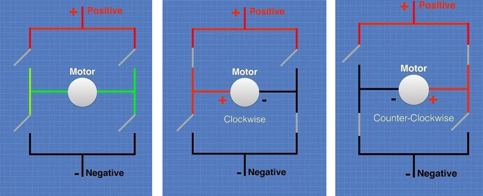
Now that we know how DC motors work, how you can reverse their direction by changing polarity. There is an easy way to do this using a very common circuit configuration called an “H-Bridge”. An “H-Bridge” is simply an arrangement of switching the polarity of the voltage applied to a DC motor, thus controlling its direction of rotation using transistors. Using transistors also allows you to control the motor speed with PWM.
In the first diagram we can see four switches which are all in the open or “off” position. In the center of the circuit is a DC motor. If you look at the circuit as it is drawn here you can distinctly see a letter “H”, with the motor attached in the center or “bridge” section – thus the term “H-Bridge”. If we close (i.e. turn on) two of the switches you can see how the voltage is applied to the motor, causing it to turn clockwise. If you open those switches and close the other two, this causes the polarity of the voltage applied to the motor to be reversed, resulting in our motor spinning counterclockwise. (image credits https://dronebotworkshop.com/dc-motors-l298n-h-bridge/)
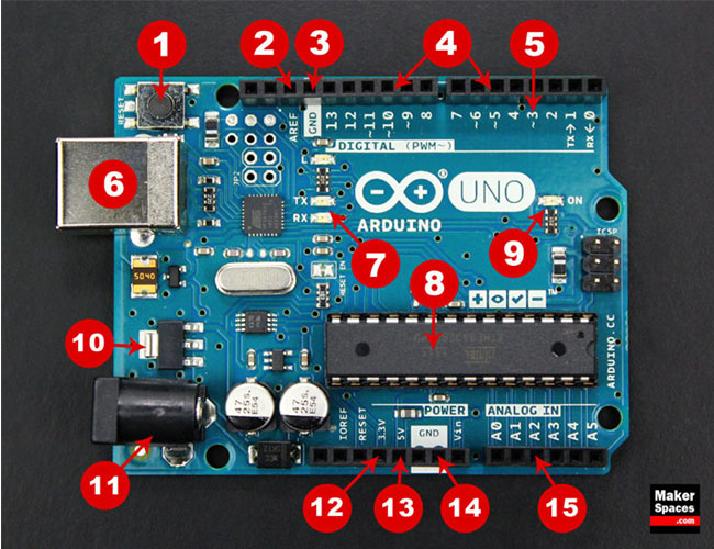
Luckily, I didn’t have to use an H-bridge, because the Arduino motor shield has built-in H bridges, which can drive several motors. You have to connect the DC motor to one of the channels (A or B) and by addressing special pins you can select a motor channel to initiate, specify the motor direction (polarity), set motor speed (PWM), stop and start the motor, and monitor the current absorption of each channel. Here are the assigned pins and their functions
Function Channel A Channel B Direction Digital 12 Digital 13 Speed (PWM) Digital 3 Digital 11 Brake Digital 9 Digital 8 Current Sensing Analog 0 Analog 1
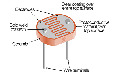
Limit Switch
The next component, which was new for me, is the limit switch or microswitch. The video below is explaining how it works.
I have used an LCD and a piezo transducer during the output devices week. This time I will use a buzzer instead of the piezo transducer, but the working principles are very similar for both of them. Here you can find the information about their similarities and differences. - Assembling and programming the electronics
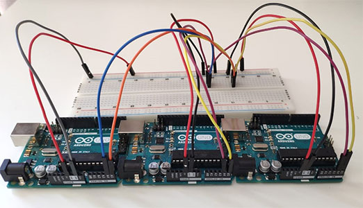
First of all I wanted to check the operation of the DC motor. That’s why I connected only the motor to the Arduino motor shield channel A. I have powered the motor shield using a 9V battery.and connecting the battery holder’s power line to the VCC of the motor shield and the ground line to the Ground of the motor shield.
I have tried to drive the motor according to this tutorial, but was not careful and didn’t see that this is for another shield. Then I used the code written by my classmate Ashot for the Output devices week, which worked.
The next step was connecting the button and limit switches. I have connected the Ground pin of the motor shield to the one of the negative rails on the breadboard to have a common ground. Then I connected the common pins of the limit switches to the Ground and normally open legs to the digital pins 4 and 7 of the motor shield accordingly using jumper wires.
Then I connected the pushbutton to start. I have attached the pushbutton to the breadboard, one of the top legs to the Ground line and the other leg to the digital 2 pin of the motor shield.
I have attached the buzzer to the breadboard as well and connected it’s negative pin to the ground and the positive pin to the digital pin 8 of the motor shield.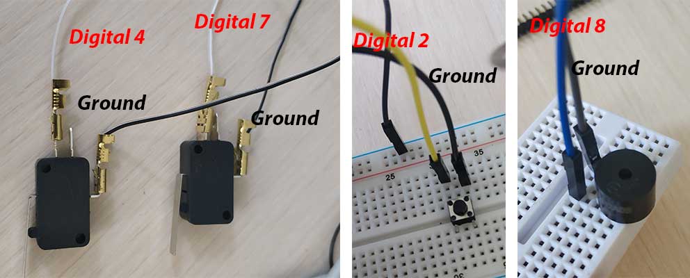
And the last thing is to connect the LCD to the circuit. As we have and LCD display module with 4 pinouts, it was easy to connect to the motor shield: VCC to the 5V, GND to GND, SCL to SCL, SDA to SDA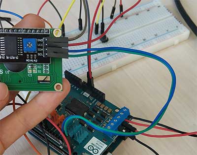
After doing all the connections, I uploaded the following code to the arduino board and it worked..
Of course, this code was written and checked step by step. First of all I have checked the response of the motor to the switches. Then I have added the LCD and buzzer part.
The only new command that I have used, was the do...while loop. By using this we are asking to do commands until the statement in the argument of while is true. -
Making Arduino Shield
After connecting all of the components I have realized that there are a lot of wires connected like a spider net. While I was looking for a solution to minimize the wires, our instructor babken suggested designing and making an Arduino PCB shield which will be attached to the motor shield and will have all of the traces on it. In the beginning I didn’t understand how to do that, but during my research I found this video and got the idea. After that designing the board in KiCad was very easy.
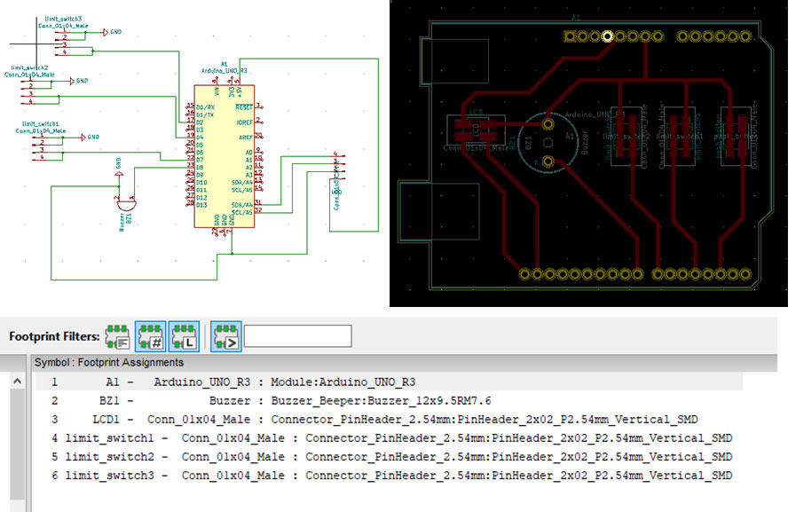
- In the schematic view of Kicad from the components library I chose an Arduino Uno R3 board, a buzzer, and 4 connector pin headers. I will connect them to the board and attach wires coming 2 limit switches, LCD and the push button. This is a more optimal way than soldering the wires, because if the component stops working you can easily disconnect it from the pin header and change instead of doing desoldering.
- I have assigned and connected using the wiring tool the ground pins for all of the components to each other and then the common ground to the Ground pin on Arduino.
- Then I connected the digital pins accordingly using the wire tool.
- After annotating the schematic, choosing footprints and generating the netlist, I went to the PCB layout editor and imported the generated netlist there
- As I wanted all the traces and components to be on the Arduino layout board, I moved the components on the arduino and started to draw the traces. As I don't have many components and complicated connections, it was very easy to draw the traces
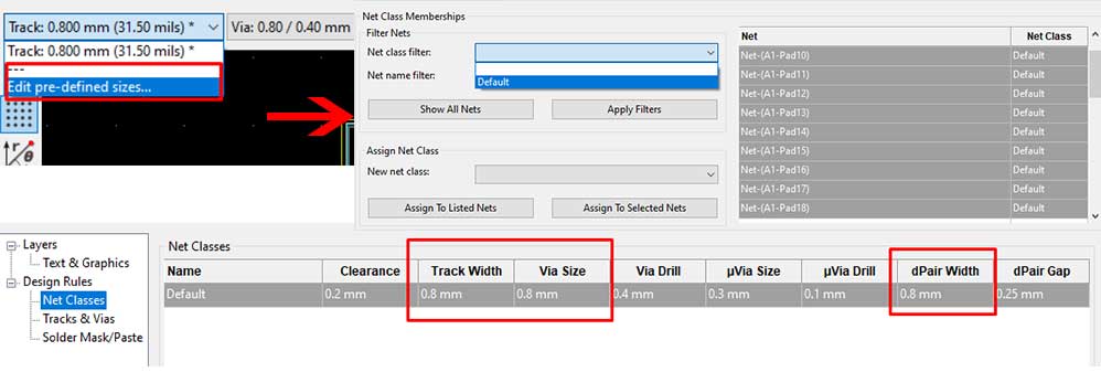
- I increased the thickness of traces from design rules. Go to the top right corner, select Tracks → Edit pre-defined sizes and change the size of traces there.
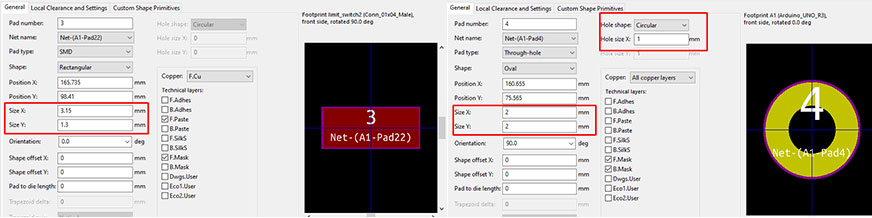
- We measured the thickness of the pins, which will be soldered into the holes with the caliper and it was 0.8mm. That’s why I have changed the footprints of arduino holes making the 1mm and the circle size to 2mm. Also, I have increased the footprints of connector headers as well.
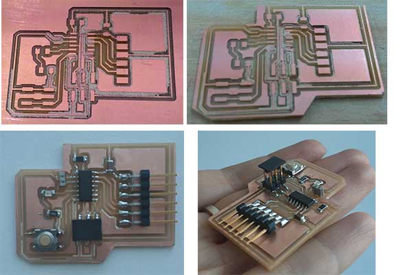
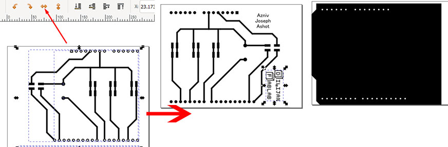
- I drew the edges of the PCB end exported both the board and interior as svg files.
- As I have to flip the board to attach it to the motor shield, the design needs to be flipped accordingly. So I opened the svg file with Inkscape and flipped it horizontally. Then removed the holes from the traces file. We decided to add our names on the board as well, so using the Text tool I added our names and “Dilijan Fablab” texts on the board.
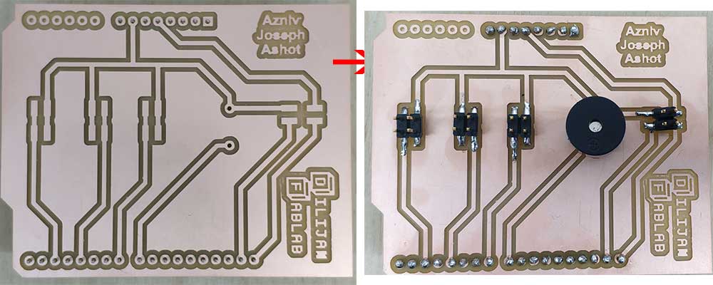
- Then I generated the G codes on the fabmodules.org, milled and assembled the board.
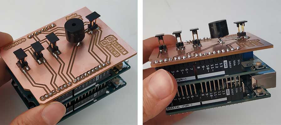
- It fitted the motor shield perfectly and will make connections more nice and practical.
-
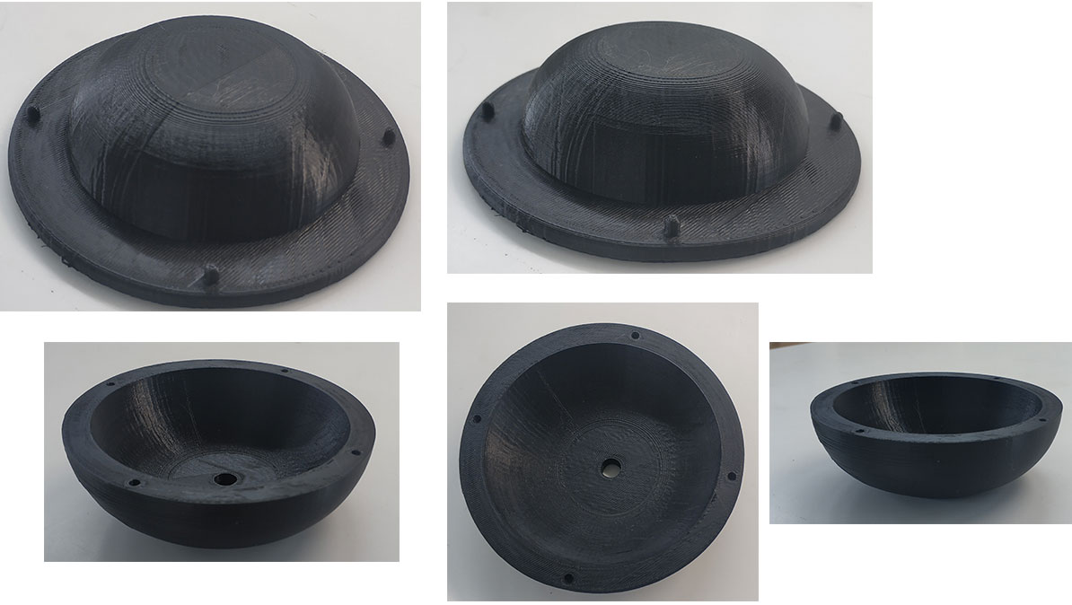
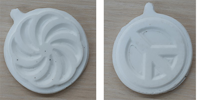
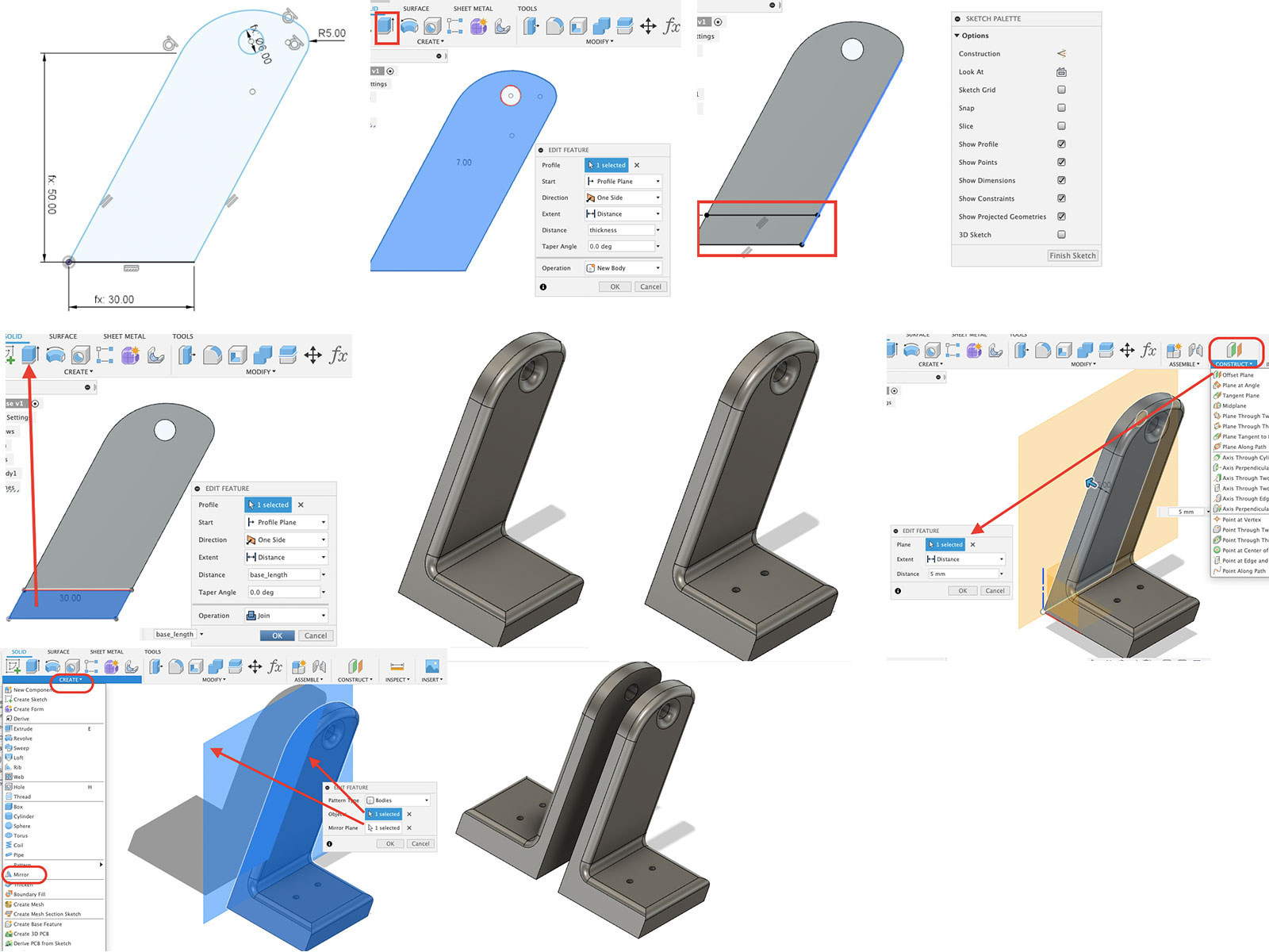
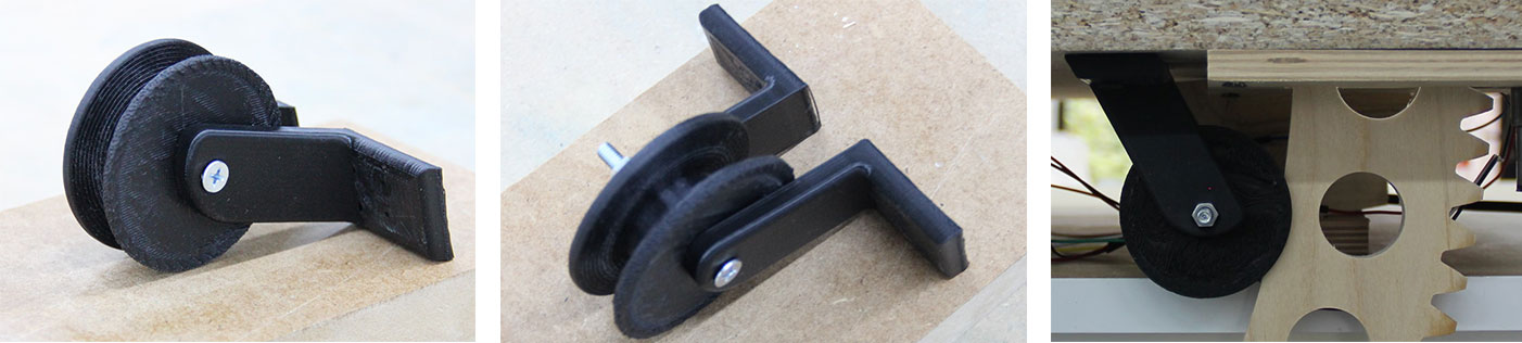
Roller to fix the gear
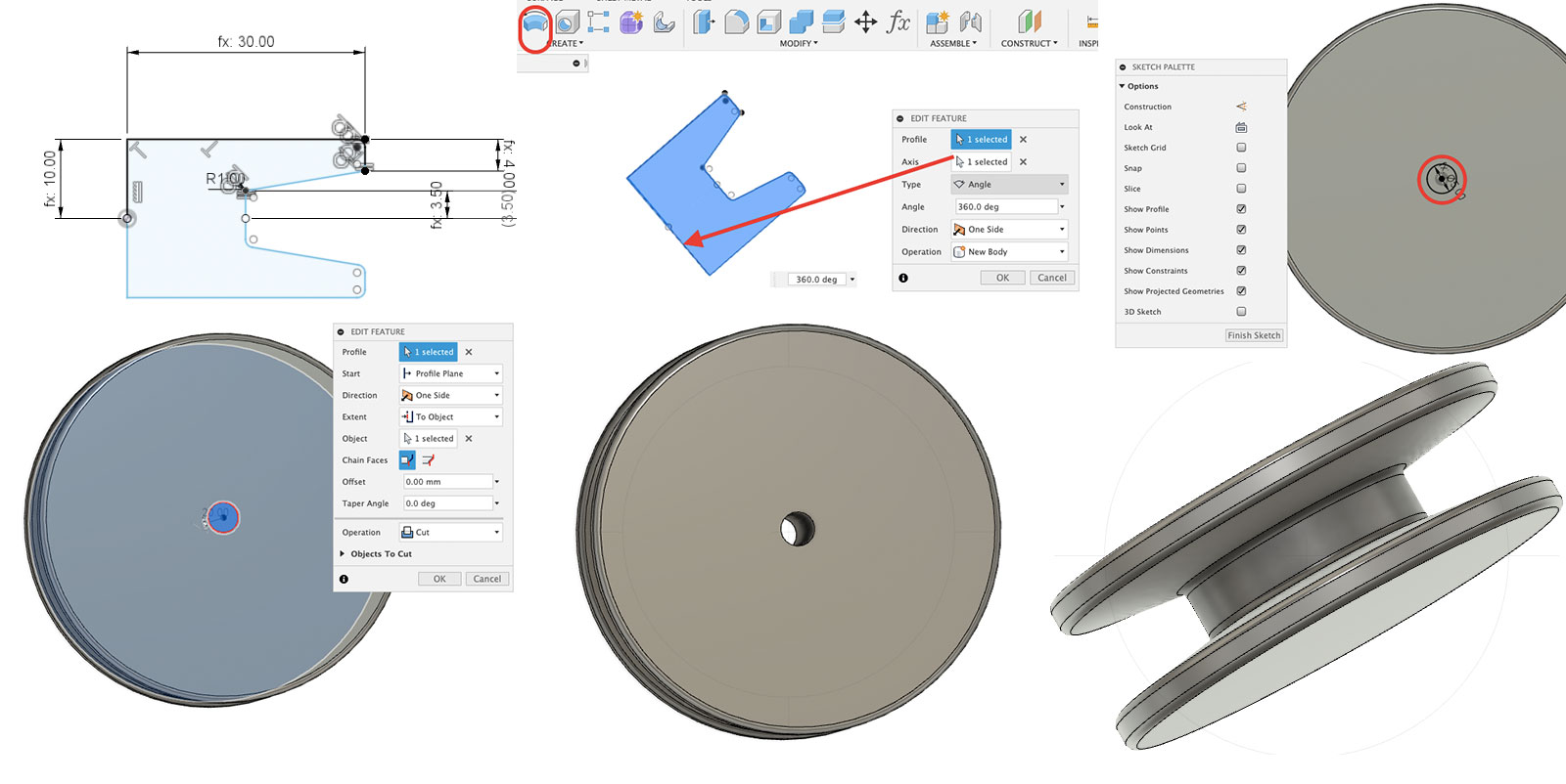
The mechanism for lifting the dynamic plane consists of a worm which is connected to the motor and a gear. We had a problem there, because the gear was shaking around the vertical axis during the move. So we have decided to design and 3D print a roller, which will fix the gear between two sides and it will not move around the vertical axis.
I did the 3D design and printing of the roller and two holders for it. Here is the process of design and the final result
-
Conclusion
During this week I could once more understand pros and cons of the group work. We are three different people in the group with different skills, strengths and weaknesses, so we could combine our skills and get a good result. On the other hand, the result depends on many people, so it was a bit hard to schedule the work properly.
This was a very good learning experience for me, as I have learnt how to drive a DC motor, how the worm-gear mechanisms work, how to consider every small detail while making a machine.
In the end we have a useful machine, which has many ways to be developed and be more practical and less time-consuming.
I think this was a very good trial before the final project, because we could learn from our mistakes and design the final project timeline better. -
Files
Design fies and G-codes for Arduino shield
Arduino code for the machine
Design and stl files for the roller