Week 5: 3D scanning and printing
Assignment for this week:
Group assignment: Test the design rules for your 3D printer(s)
Individual assignment: Design and 3D print an object (small, few cm3, limited by printer time)
that could not be made subtractively
3D scan an object (and optionally print it)
- Introduction
I enjoyed this week, because it was full of creativity. I have seen and used 3D printers for the first time, tried new tools and features in FreeCAD, learned about the differences of additive and subtractive manufacturing. Here are some sources where I could find information about that differences.
Difference Between Additive and Subtractive Manufacturing
Additive vs. subtractive manufacturing – what’s the difference?
I did a 3D print of a bike part, which was not as good as it could be but I have learnt a lot from the mistakes I have made. Later on for the Wildcard week I did another design in Fusion360 and did a better 3D print.
I tried 3D scanning in Meshroom and 3DF Zephyr, which was a very exciting experience for me. I met a lot of problems but this was a way to learn about the software. -
Additive and Subtractive Manufacturing
According to the sources mentioned above, additive manufacturing is a process that adds successive layers of material to create an object, often referred to as 3D printing. Subtractive manufacturing, as the name suggests, is the opposite.
Rather than adding layers, subtractive manufacturing involves removing sections of a material by machining or cutting it away. It can be carried out manually or, more commonly, by a process known as Computer Numerical Control (CNC) machining.
There is also a possibility of Combining Additive and Subtractive Techniques for Hybrid Manufacturing. This is being done in two ways: machines that can operate through both additive and subtractive, and parts that are made with both additive and subtractive manufacturing. The combination of both techniques into either singular machines or even singular parts allows us as engineers to have a greater freedom in our designs. These hybrid techniques only open more doors to potential manufacturing.
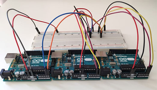
- Group assignment: Testing 3D printers
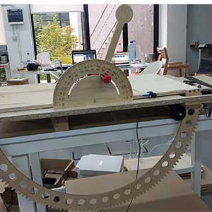
As a group assignment we had to test the design rules of our 3D printers. We downloaded overhang and bridge test from Thingiverse and printed it using both of our Makerboth replicator printers . One of them printed pretty good, we could see that even the bridge of 2inch length doesn’t need support and has a good quality of printing for overhangs up to 50deg. For the other one we had leaked material, very bad printing etc. In this website you can find most common 3D printing issues along with the software settings that you can use to solve them. Joseph did the troubleshooting and calibration of the printer and it started to print better but not as good as the first one. We have another printer Ender 3 , we tested that as well and printing was very good. Here as well, a bridge of 2inch length doesn’t need support and has a good quality of printing for overhangs up to 50deg. Besides that, we didn’t have leaking material lines and curvity.

- Designing the model
I had trouble coming up with an idea of drawing, which fits the criteria of the assignment. I had different nice ideas but they were either too simple or too complicated to design, considering my abilities so far. I watched many tutorials and found this one nice and suitable. This can be used as a bike accessory if you want to connect something to the bike seat. Following the step-by-step tutorial, I designed the kit.
I worked in FreeCad. First of all, I did the sketch of the view from the top. Here i used some new tools which were new for me i.e. creating different types of arcs, making tangent lines etc.
After having a 2D sketch, I did pad and then created a new datum plane, which is perpendicular to the one, where I have sketch. On that datum plane I did the sketch of view from the side. Afterwards, I went to Tasks -Pocket tool to cut the unnecessary parts and keep only the view that I need. In the options I chose Through all.
When the part was ready, I did fillet on some of the edges, to have more smooth edges. Eventually I exported my design as an .stl file and it’s ready for printing.
Original design file of bike detail
stl file of bike part
- How NOT to do 3D printing
As I was very excited to do my first 3D printing, I didn’t have patience to go deep inside to printer settings. I changed some of them before printing, but because I didn’t explore some settings in detail, I had some issues. Here are the settings that I put and the result of the printing.

As for me, failure is a way to recognise mistakes, I started to explore more to understand why I have this or that issue.
-
Too many supports: I was thinking that the program will automatically detect where and how many supports the model needs. Actually it does, but
on this website I found some tips and could do the following actions to avoid having too many supports.
- Orient the print correctly. I have too many supports in the bottom, because I just chose the option “On the platform” in Makerbot printer settings. If I simply rotated the object so that the flattest part was on the platform, I would need way less number of supports.
-
Set support density. Here are some factors that affect support density:
- Print speed. Faster you print, the less dense your supports need to be to get a good quality finish.
- Desired print quality. Higher quality overhangs, you can increase density (at the cost of wasted material and print time). If it’s too high though, support removal can sometimes damage the print.
- Size of overhang. The bigger the overhang, the denser supports you need. Especially for 90 degree overhangs, a support density of at least 15% is recommended.
- Support removal. The denser the supports are, the harder it is to remove them. Also, the denser supports are, the more material you waste.
- Infill density and style:
Infill is simply a repetitive structure used to take up space inside an otherwise empty 3D print. Depending on the structure and the way you want to use the object, you can choose different factors of infill.
Here you can find more information about that
- Infill styles: Infill comes in many shapes, sizes, and patterns. Each style has its own strengths and weaknesses, and each its own use. Though infill can take countless forms, there are several fairly standard patterns like honey, linear, grid etc.
- Infill density. Infill density varies from 0% which is the empty model to 100%, which is the solid one. You can choose numbers in between those, depending how strong and heavy you want your object to be.

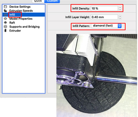
In my case I had 20% infill density with the linear infill style, which was too much for my model. I could do 10% infill density which would save me the time as well as the material. More about the custom printing options for Makerbot replicator is here
-
Too many supports: I was thinking that the program will automatically detect where and how many supports the model needs. Actually it does, but
on this website I found some tips and could do the following actions to avoid having too many supports.
-
Updates on 3D printing
I did one more 3D printing for the Wildcard week assignment. You can check design process there. As this was my second attempt in 3D printing, the result was more satisfying.
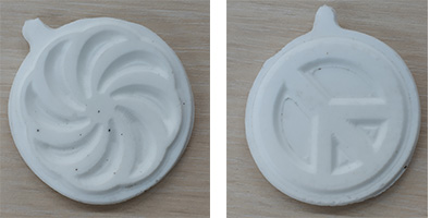
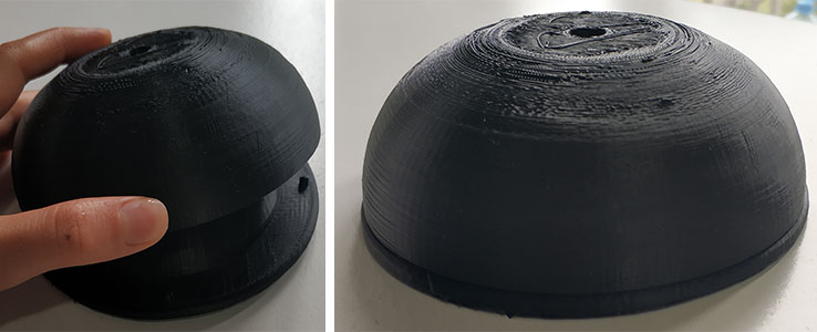
One of the goals for 3D printing assignment was to do something, which can’t be easily made subtractively. To make this bowl subtractively the machine would need to reach from at least 3 axes, considering the fillets, holes and guides on the base. So, I believe that I achieved the goal.
As the 3D printers were not used for a long time, I started with leveling the build plate following instructions from the user manual. It is important, because if the build plate is too far from the extruder nozzles, or if one part of the plate is farther away from the nozzles than another part, your 3D prints might not stick to the build plate. If the build plate is too close to the extruder nozzles, the build plate can block the MakerBot Filament from extruding from the nozzles. This can also tear the Kapton tape applied to the build plate and scratch the aluminum surface underneath.
Go to Utilities from the printer menu and choose Level Build Plate. Afterwards tighten the knobs [turning them counterclockwise] to move the build plate away from the extruder nozzles or loosen the knobs [turning them clockwise] to move the build plate closer to the extruder nozzles. The distance between the extruder nozzles and the build plate should be about the thickness of the MakerBot Support card included with your MakerBot Replicator 2X. I didn’t have that card and used 0.1mm thick A4 paper instead. During the process of adjusting the knobs the paper should just slide between the nozzles and build plate. You should feel some friction on the paper/card but still be able to easily pass the paper between the plate and the extruder nozzles without tearing or damaging the card/paper.
After adjusting the build plate, I opened the Makerbot desktop and added my stl files there. As there are no big angles and long distances for the extruder to pass during this process, I decided to print without supports.
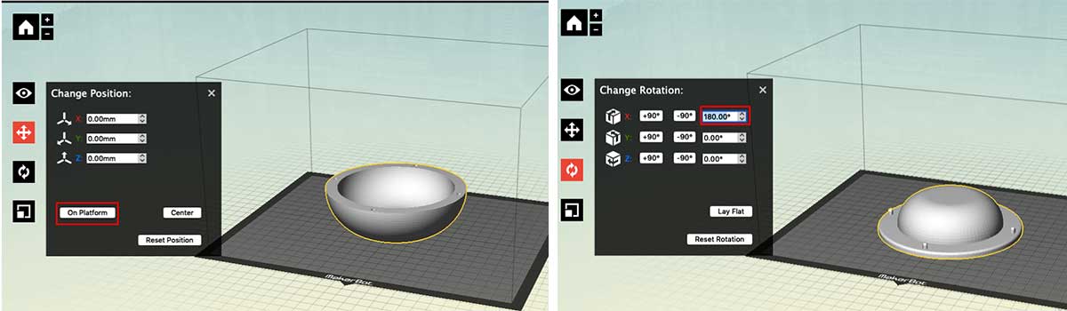
For the inner bowl I applied 180deg. rotation angle for two reasons: I am going to use the outer part of it, so this face should be smooth. Secondly, this way I will avoid using supports and guides will be printed easily.
For the outer bowl I am going to use the inner surface, so left it as it is, on the platform.
For both objects I applied 10% diamond(fast) infill.
The results of the prints are quite satisfying.
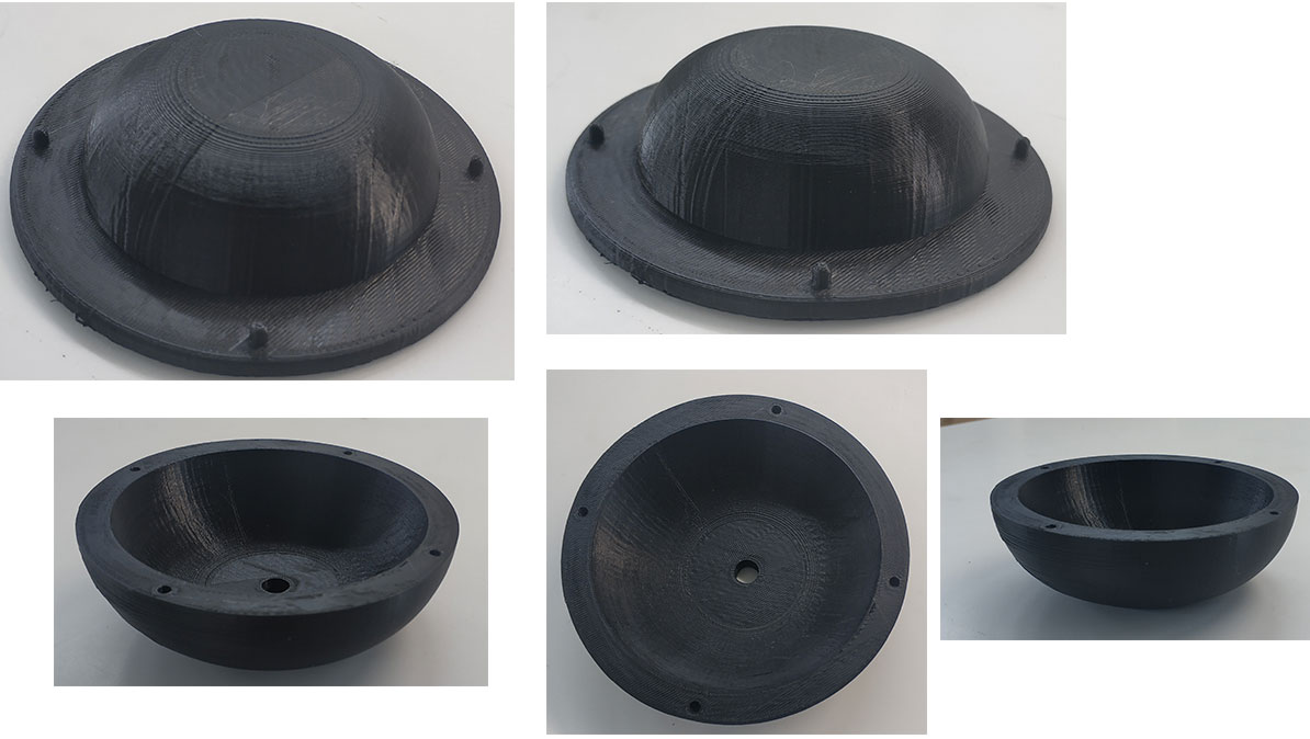
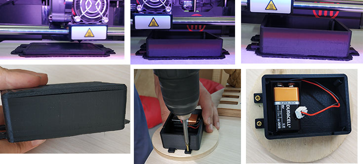
The only thing that I didn’t consider was the tolerance of the guides, but I loosened the holes a bit using a drill machine.
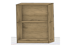
As a part of my final project I had to make a 3D printed box for electronics. The whole process of the design and printing is on my final project page and here is the result:
-
3D scanning, photogrammetry
Before starting 3D scanning I have explored the tools and software for that. This article is very helpful and gives detailed information, prices and comparison about 3D Scanning Software. From all of them Meshroom was quite popular and seemed very user friendly, so I have decided to use it. It is an open source photogrammetry software for Windows and Linux. I found a very good tutorial for beginners and did my first steps.
I put a toy motorcycle in the middle of a round table and took photos from different sides, moving around the table. As a device for taking photos (3D scanning) I have used my Canon 750D camera. This way I was keeping the same distance from the object. I took photos from all the sides and top.
Then downloaded Meshroom for Windows and opened it. Afterwards, drag and drop taken images to the Meshroom workbench, save the file and press the Start button. I didn’t change any setting, left as it was. After a while I got an error on the DepthMap step.

I did some research to understand the reason. In the forums people were suggesting different solutions:- Remove images which were not rendered and start the process again
- Decrease the max point process at the end of the node
- Download the older version of the Meshroom
I have tried all of these options, but still it kept stopping on the same step.
My doubt was the quality of the photos. My classmate Joseph did photogrammetry and had very good results, so I was offered to use his photos. He is a professional photographer, so the quality of his photos are very good. I have tried his photos as well, all the images were rendered but again the program stopped on the DepthMap step. When I went to the log, I found out that the problem is with my GPU. That’s why I started to look for another software.As an alternative I chose 3DF ZEPHYR. It is very user friendly, easy to use and there are many tutorials for beginners in the official website. The free version has limitations: you can upload maximum 50 images. And it runs only on Windows.
- I chose 50 photos and added them to the program. Then pressed Next without changing settings, because according to the tutorials presettings work well for beginner level photogrammetry. After a while the model was ready, even though some images were not reconstructed.
- Go to Workflow → 3D Model Generation Here I chose Close range and High details in the settings and pressed Run.
- Go to Workflow → Dense Point Cloud Generation. Here I chose Close range and High details in the settings and pressed Run. You can run this step as many times as you want, adding new images for the missing parts.
-
To remove the unneeded noise parts go to Tools → Selection → Manual selection.
Here you can choose different shaped tools: rectangle, triangle, polygonal, etc. When you select the area you can press the Add button and select another area as well.
I have deleted noise as much as I could using rectangle and polygonal tools and pressing Delete.
You can Pause the selection each time you want to move around the object. - As there are holes on the objects, I did Tools → Mesh filters → Fill Holes → Selective and select the holes you want to be filled.
- Press Workflow → Mesh extraction to extract the mesh.
- And finally, go to Workflow → Textured mesh generation. It will take some time. Afterwards you can export the generated mesh. I exported an OBJ file.


When I was familiar with the tools of 3DF Zephyr and was sure that my computer supports it, I decided to do one more 3D scanning with my own photos. I found this tutorial, which clearly shows how to take photos for proper photogrammetry.
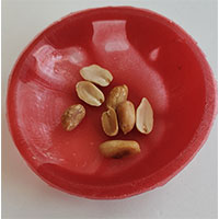
I decided to use a smaller object this time, so I took photos of a fossil, which we have at home. I put it on a colorful book, to have a noisy environment, so that it will be easier for the program to detect the camera position. Luckily, all of my photos were rendered and I got this result after the 3D model generation step.
I deleted the noise and filled the holes, and here is the result.

Afterward, I have generated mesh and exported it as an OBJ file. -
Conclusion
This week was very effective and productive. I did 3D modeling and printing, using new tools in FreeCAD and completely new for me machines. Even though I have made some mistakes and didn’t follow some best practice rules, that taught me to be more careful, read the instructions, tips and best practices before using machines and materials.
I did 3D printing later for Wildcard week as well, which was more efficient and the result was better quality.
For the 3D scanning I used Meshroom first, but because of the requirements of the laptop I couldn’t complete it. Later on I found a 3DF ZEPHYR program, which worked well and I had quite good results. The only problem for me was taking proper photos for the 3D scanning, that’s why I used photos taken by my classmate Joseph. He’s a professional photographer, so could meet the requirements of the program. And it was interesting to compare results from the same set of photos in different programs. I believe Joseph has better results in Meshroom, he even managed to 3D print a part of the scanned statue.
After watching tutorials on how to take proper photos for photogrammetry, I took photos of a fossil and could generate a pretty nice 3D model of it. -
Files
Bowl stl files
Bowl design files
Original design file of bike detail
stl file of bike part