Week 7: Computer-Controlled Machining
Assignment for this week:
Group assignment: Test runout, alignment, speeds, feeds, and toolpaths for your machine
Individual assignment: Make (design+mill+assemble) something big
- Introduction
This week I have designed a bookcase. It was a very effective and productive week for me, because I used some techniques in Fusion 360 and developed my designing skills Besides that, I have learnt how to prepare designs for CAM, how does the ShopBot CNC machine work. To be honest, the process seemed less complicated than it actually is, but in the end I had good results. One of the key factors in working with a CNC machine is following the safety rules and being sure for 110% that your design is good.
-
Designing the bookcase
On the first attempt I wanted to design a round table using this tutorial and wanted to do some changes in it. I did some work in Fusion 360, almost to the end but then I found this video and decided to design and make a bookcase, as here I could do more new things in designing. Even though the tutorial is very detailed, I managed to struggle on some parts. I will not go into many details here, as it’s not the first time of designing and some basic functions should be clear so far.
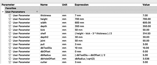
- As it was advised to do prototyping with a laser cutter before doing actual machining, the design should be fully parametric. For that I created the parameters which I will need to use. For example material thickness, bookcase height, width, depth, etc.
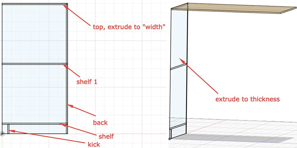
- Create the sketch of one of the sides.
- Extrude the top to the parameter “width”
- Extrude the rest of the sketch to the parameter “thickness” and we will have the one side of the bookcase.
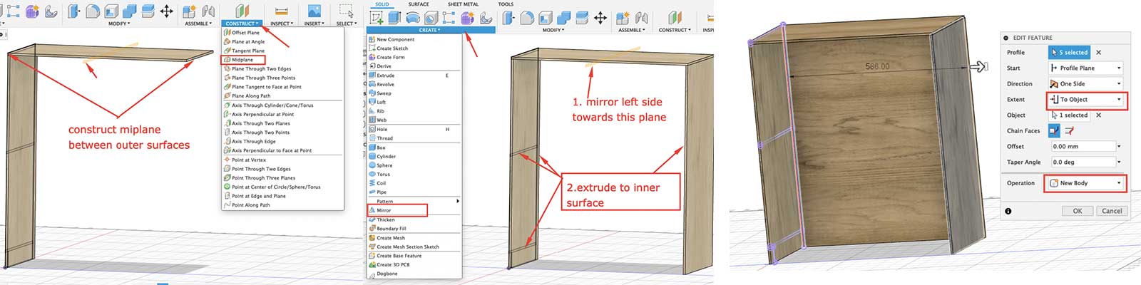
- As I needed the same block on the other side of the bookcase, I created a construction midplane and mirrored the left side towards that midplane. This was one of the things I have never done before and I found it really helpful.
- To create the same sketch on the inner side , I did “Create sketch” there and did , took all the necessary drawings from the first sketch. Create → Project
- Then I extruded all of the parts to the inner surface of the second side. For that in the opened extrude window choose “To the object” and select the surface you want. In this case if we change a parameter, it will automatically change everything accordingly.
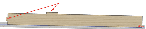
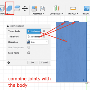
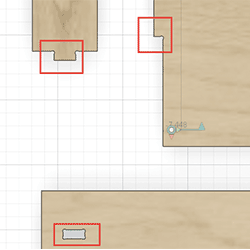
- Now it’s time to create joints. For that I take a surface of the body, create a sketch on it, extrude to another surface and keep as a new body. Afterwards I did mirror again towards the midplane. Then we can join new created joints to the main body.
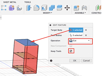
- When we have joints, we should have holes for them. To create the holes, we can use Assemble → Joint , choose the body on which you want to have holes, bodies which will connect to the main one and then in the window choose cut and tick the Keep tools box.
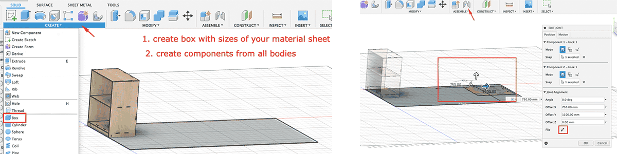
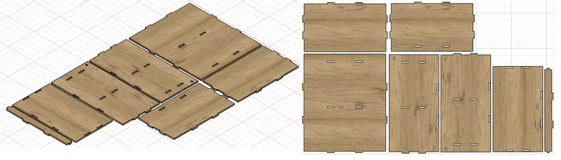
- Now we have a ready bookcase model designed. For fabrication we need to have this model to be lied down flat. To do that I created a box on the bottom plane with approximate dimensions of the wood sheet I’m going to use.
- Select all the bodies, right click and select Create components from the body. We will have components for every part.
- Right click on the just created box component and press “Ground”. This will pin it to its place.
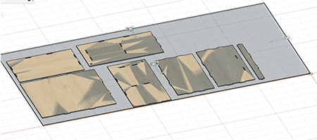
- Go Assemble → Join , take the inner surface of the parts and do join them with the base box. You can then move them on the plane to have minimal material waste.
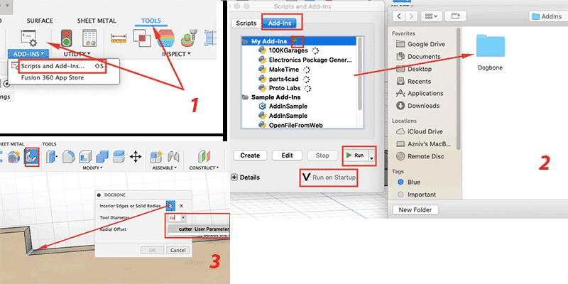
- To have more tight joints, it’s better to use Dog bone fillet on the corners of the joints. I found an Add-In for Fusion 360 here and added it. Here you can find a guide for adding that. After Add in is added and running, you will see the icon in the Create tab.
- Ideally you could select the surface and the Dogbone feature should identify vertical corners and automatically create dogbone fillets. It didn’t work in my case and I could not do troubleshooting, so decided to do manually selecting corners.
- Finally I have the my design with dogbone fillets ready.
-
Preparing design for CAM
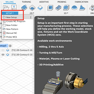
To prepare the design for CAM, first of all we should change from Design to Manufacture workspace from the top left corner.
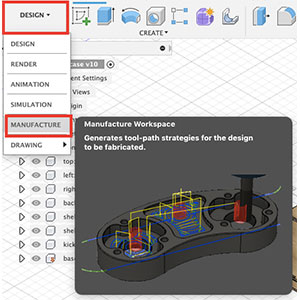
- Press Setup and choose New Setup. Here we set up the operation type (in this case Milling), stock size, set Work Coordinate System (WCS) zero.
-
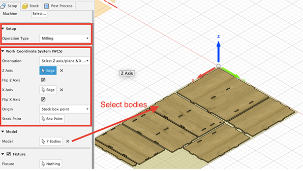
In the first (Setup) tab I have selected the operation type as milling.
I was not careful while doing the design and my coordinate system did not match the one on CNC machine. Luckily, here we can choose the Work coordinate system (WCS) and I put Z to the top and X and Y axes accordingly as on the machine. Actually, I didn’t know about this feature and was going to design again. Then I found information about WCS in this video and it saved a lot of my time.
In the Model part we should choose the parts which we are going to cut. - In the Stock tab I put stock mode as Fixed size box and inserted the parameters of my stock material (2440*1220*10mm). Also, I have put offset from the X and Y axes, so that the tool can pass there. After doing all of this, press OK
-
In the first (Setup) tab I have selected the operation type as milling.
-
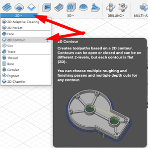
The next step is creating toolpaths. I followed the advice from
Ashot, who is doing CNC machining for a long time and created two separate toolpaths: one for holes and the second one for the outer contours .
By doing this we avoid possible slight movement of the parts before the all holes are cut.
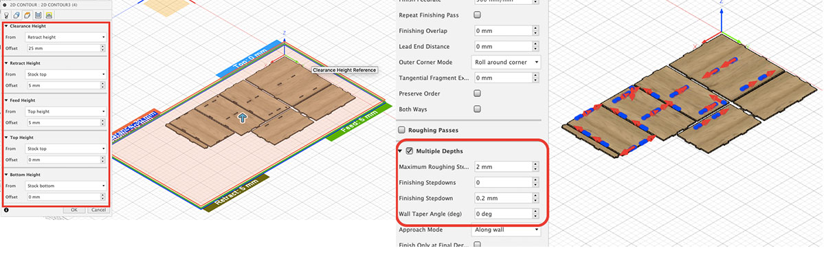
For both cuts I chose the 2D Contour toolpath with following settings.
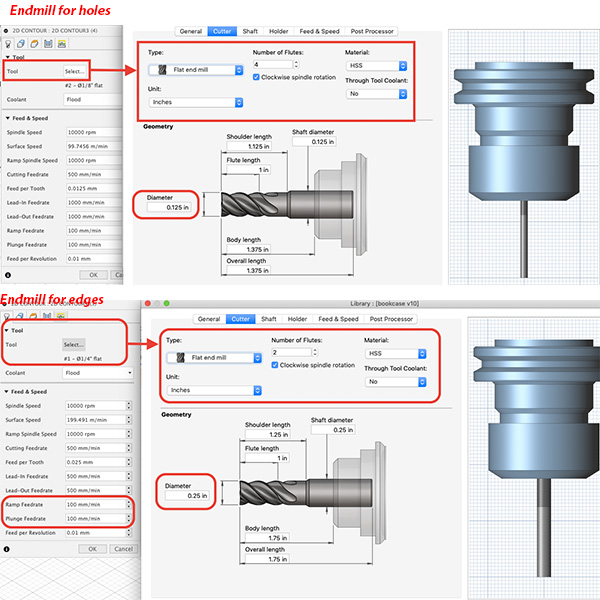
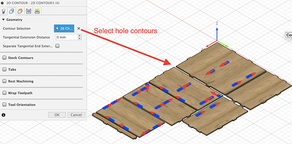
- For the holes
- I am going to use a ⅛ inch flat end mill with 4 flutes. For the Tool tab I clicked on the Select button and added a tool with the characteristics mentioned above.
I have also lowered the Plunge Feedrate , which is the speed of the tool when it goes vertically to the stock.
- In the Geometry tab I have selected all of the hole contours which should be cut.
- The rest of the settings are shown in the image below.
- I am going to use a 1/4inch flat end mill with 2 flutes. For the Tool tab I clicked on the Select button and added one more tool with the characteristics mentioned above. Here as well lowered the Plunge Feed Rate.
- In the Geometry tab I have selected all of the outside contours. here I have added tabs on selected points. In this case machine leaves a small uncuted part on the selected points, so the cuted parts will not move.
For the edges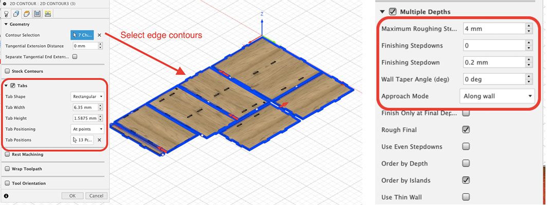
- I am going to use a ⅛ inch flat end mill with 4 flutes. For the Tool tab I clicked on the Select button and added a tool with the characteristics mentioned above.
I have also lowered the Plunge Feedrate , which is the speed of the tool when it goes vertically to the stock.
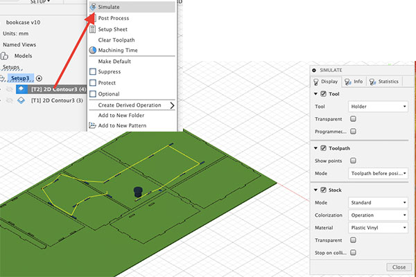
- Before exporting the toolpath we have to be sure that everything works as it is supposed to. For that right click on each of the toolpaths and choose Simulate. Here you will see how the tool works on the stock.
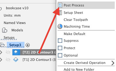
- If everything is fine, right click on the toolpath and select Post Process. Here we should choose the Post processor and that’s it.
- Press Setup and choose New Setup. Here we set up the operation type (in this case Milling), stock size, set Work Coordinate System (WCS) zero.
-
CAM
Before working with any machine it’s very important to understand how it works and what are the safety procedures to follow. In the lab we have ShoBot CNC machine and I could find all the needed information in ShopBot User guide. Our instructor Babken was with me and helped with tips as well.
Here are the safety rules to follow, which I took from the user manual.- READ. Read this manual well to acquaint yourself with how to handle the tool safely and effectively before use. Read related manuals for the router and/or spindle that will be mounted on your ShopBot.
- PRACTICE. Practice operating your ShopBot tool with your computer and the ShopBot Control Software BEFORE activating the router or spindle.
- PROTECT. Turn OFF your router or other power tool before loading or positioning a workpiece or adjusting the position of the tool. Do not change router bits or other cutters without first unplugging the power tool or having a positive system to make sure the power tool is not accidentally activated. It is your responsibility to use it safely.
- HOLD-DOWN. Never attempt to cut wood or other material without first ensuring that the work is firmly secured to the work surface. Power cutting tools always carry the risk that work material or broken cutters will be sent flying towards the operator or others in the area. A tool like ShopBot allows you to work with the workpiece secured and thus greatly reduces this risk. It also allows the operator to be away from the cutting and protected. However, YOU must take the steps to secure the workpiece and protect the operator. Note that not only must the full starting piece be secured, but you need to attend to the attachment and security of any pieces that will become cutouts or cutoffs during the cutting or machining process. Stand clear of the tool when it is in operation and protected from debris, parts, or broken cutters that might fly out during operation. Never attempt to push material by hand through a moving bit or to interact with the tool while it is running.
- AWAKE. Never operate the tool when you are fatigued.
- EYES & EARS. Always protect your eyes and ears when operating your ShopBot.
- ATTEND. NEVER leave the tool unattended while it is running. A cutting error or workpiece slippage that the tool cannot detect might occur. Some person unknowledgeable about tool operation might approach and start the tool. Or some other unexpected event might occur.
- GUARD. Always position the dust skirt correctly to guard against flying particles.
- TO STOP. During a cutting or motion process, the SPACEBAR on the computer keyboard is a Panic/Stop/Halt button. Hitting the bar will stop the tool’s movement. Your ShopBot PRSalpha also has a remote STOP Button that interrupts power to the stepper motors and the spindle or router after it is pushed. You should locate the STOP Button convenient to your tool and workstation. Note: For PRS systems the power tool is operated independently of your ShopBot, it must be turned off separately.
- POSITION. The safest location for you during the operation of the tool is within easy reach of the computer keyboard or STOP Button and well away from the path of the tool. Because bits can break and fly loose during cutting -- stand behind a protective screen.
- BE SMART. Most importantly, never place yourself at risk during a cutting or machining process by placing any part of you near the cutting path or by attempting to move or adjust the workpiece or active tool. SHOPBOT IS A ROBOT, BUT YOU ACTIVATE ITS MOVEMENT AND YOU TURN ON AND OFF ITS POWERED CUTTING-TOOL.
I did milling following the steps below
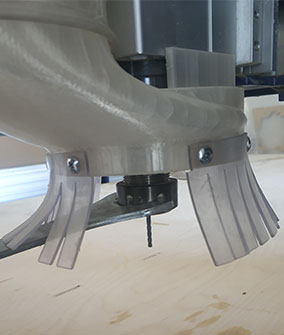
- First of all I have inserted the endmill.
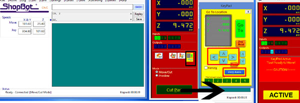
- Then I opened the ShopBot software and set zero for X and Y. For that open theKeyPad in the app and move left/right forward/backwards and bring the tool to the desired position for the zero. Then press Zero axes.
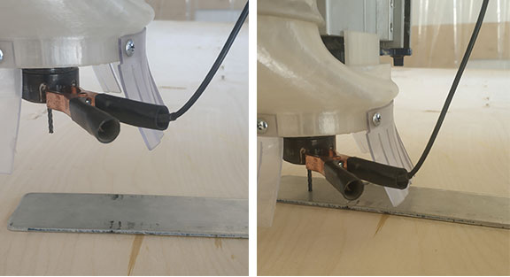
- For setting up the zero for the Z axis, move the tool somewhere in the on the table and press setup Z zero. The machine has a special tool for that. You attach a special pin to the end mill holder and a flat metallic tool under the tool on the table and press OK. The machine will set up zero for the Z automatically.
- Then press Cut Part, choose the generated post process file. I have run a half of the process in the air, to be sure that machine goes to the right directions and then set up actual zero for Z and started milling.
- The machine has a key and a place for that. If the key is not there, the spindle will not rotate.
- Start the process and always be near the machine, to stop it when it’s needed. Don’t forget to protect eyes and ears.
When the milling was done, Ashot and Babken helped me with finishing and assembling.
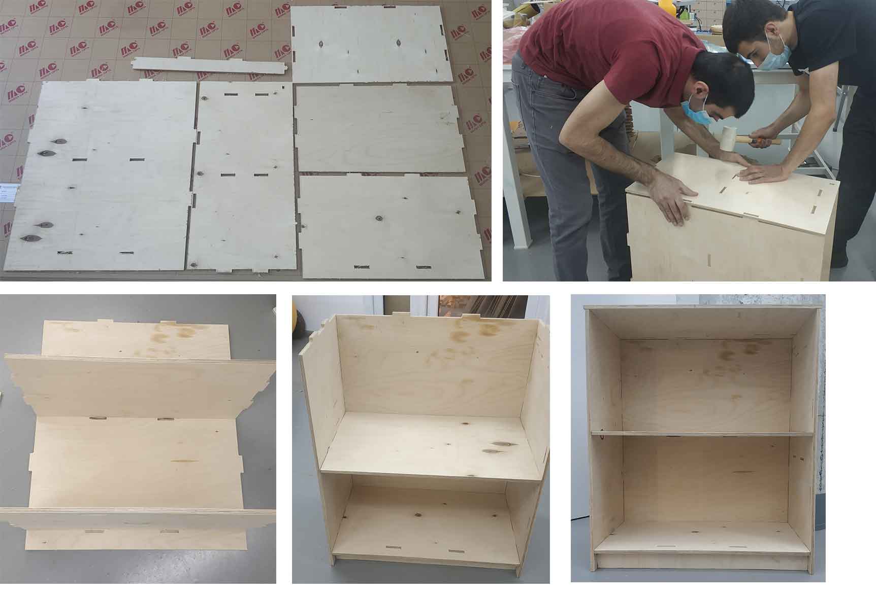
The joints were done perfectly and I didn’t need any glue to assemble it. Here is the result.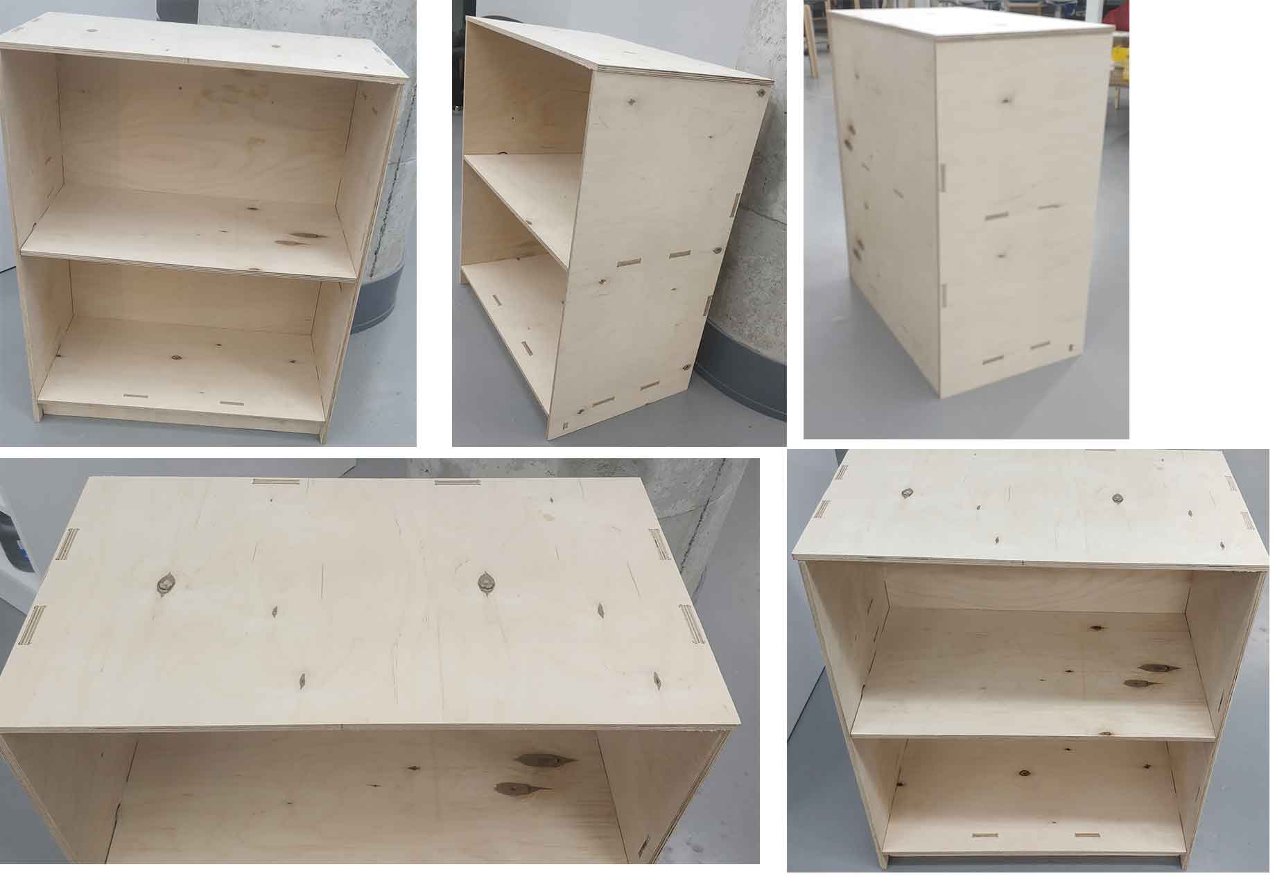
-
Conclusion
This week's assignment was super interesting and full of new things to learn. I have done design before this, but didn’t go into Manufacturing features yet, so this was a good opportunity to learn about CAM process, about the settings and their meanings.
I was in quarantine, when I did the design, so didn’t have the exact dimensions of the stock wood, but the design is parametric. Thanks to that I could just change a parameter and have a new design without any major changes. The only problem was the dogbones, because I have installed a plugin for them and after changing the thickness of the stock material I have lost some of the dogbones and had to re-add them.
I worked with the CNC machine for the first time in my life and I was very surprised and excited in the end, when I had fully assembled the bookcase without any problems. -
Files
Here is the design file and codes for machining