9. Embedded programming
Configuring AVR Tools on Mac
I am trying to program an Tiny45 ICP with a arduino uno on a mac os running Catalina. First i went through installing the toolchain for avr. This was somewhat confusing for me, but having to repeat it on two different computers made it clearer. I worked through the ladyada
when i was having issues programming my board with CrossPack I also tried working through this tutorial for manually setting up avr tools using Homebrew AVR though this didn’t end up working it gave me some more understanding of the toolchain.
brew tap osx-cross/avr

brew install avrdude --with-usb
Programing tinyISP with arduinoISP
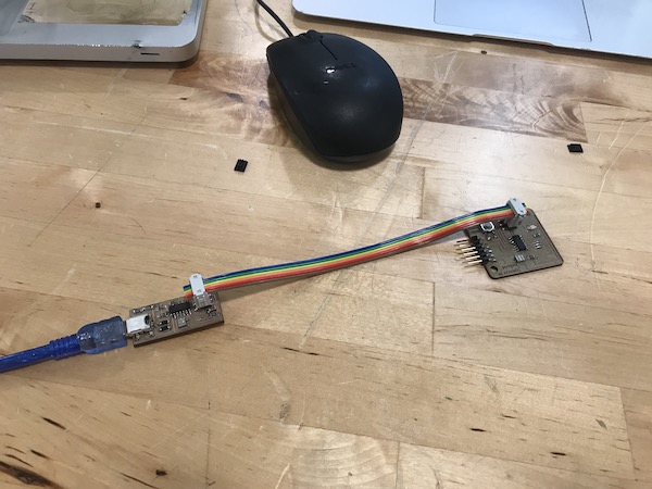
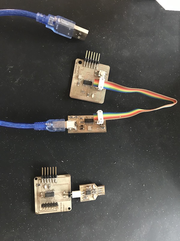
I was having very little luck uploading a sketch to program my tinyISP using the arduinoISP. I started with the Fab Academy tutorial
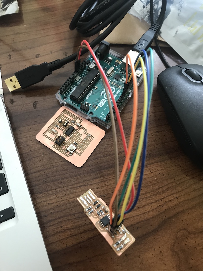
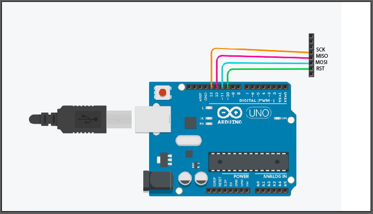
here is my pin configuration
’‘’ pin 10 to reset pin 11 to mosi pin 12 to miso pin 13 to sck ‘’‘
found this tutorial from Klein Xavier super useful. I pulled their code and modified it to use to program my board. still no luck. I decided to use an older mac. I went through the same setup for CrossPack from ladyada’s tutorial. It works!
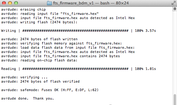
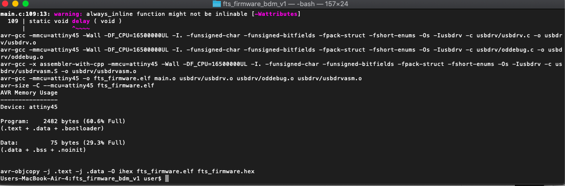
I was able to run these commands in the root file to build the hex and flash it to the IC. Since I was not able to confirm the USB worked I didn’t set the fuses.
make
make flash
make fuses
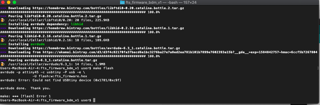
Important details from this; the programer needed to be correctly identified, along with the correct ports. . I wasn’t able to get it running on my updated mac so using the older mac was necessary. here is my configured makefile
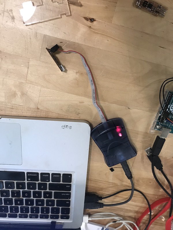
Though this seems to have programed successfully (blinking LEDs and all). I’m still unable to detect the tinyICP through the usb settings on my computer. I’m going to try another computer and hardware setup to check the usb connection. I tried reflowing the board and checking continuity between the usb and pins. I’m going to check it on a linux computer next. I think the next step is to remake the board once I have lab access
I did have a chance to try and detect my programmer on a linux computer, no luck! I’m not completely sure what my issue is. I confirmed my connections between my usb port and my IC. My instructor suggested that I try making an attiny44 based FabISP which is documented below.
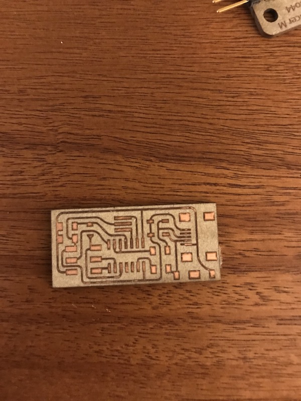
FabISP with attiny44
Back in the lab I fabricated a board based off of Ali’s excellent tutorial I found the explanation here really helpful. I liked the details on this board and the curved traces.
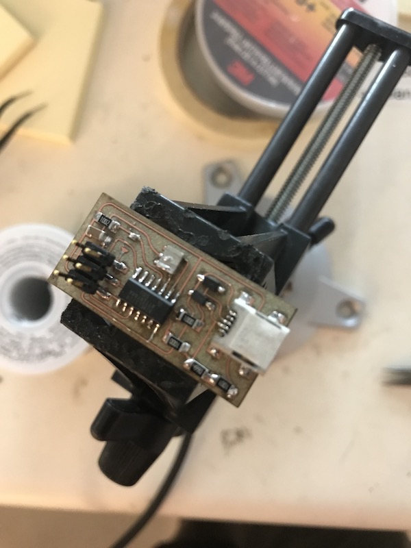 This tutorial doesn’t have much information about programming the programmer. However with my experience trying to get the Tiny45ISP working I found it to be pretty easy. I used an Atmel-ICE programmer and the older mac laptop along with Neil’s makefile.
I then run my same AVRdude make commands as documented earlier. When the boards fuses are set I then remove the 0omh jumper to allow it to function as a programmer. Success, I have a programmer that is detectable by USB and will work with the arduino IDE to program target boards. At some point I would like to revisit the tinyISP to try and understand what my issues were. for the time being I’m delighted to have a working programmer.
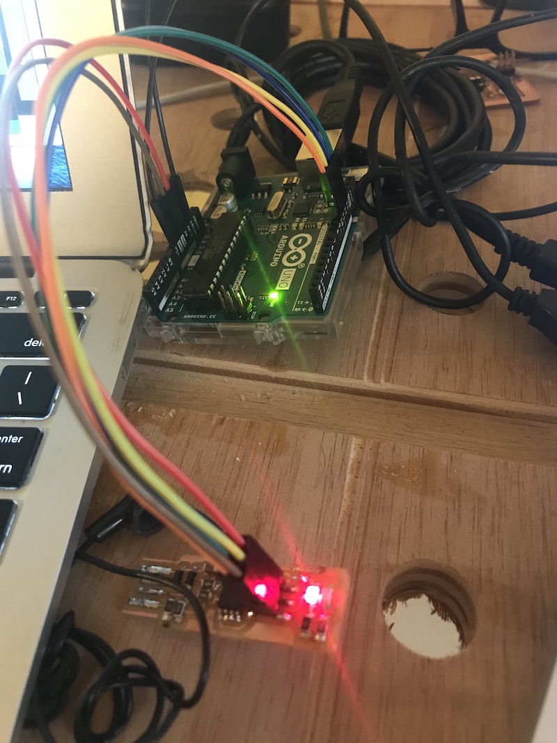
Programing attiny44 with arduinoISP
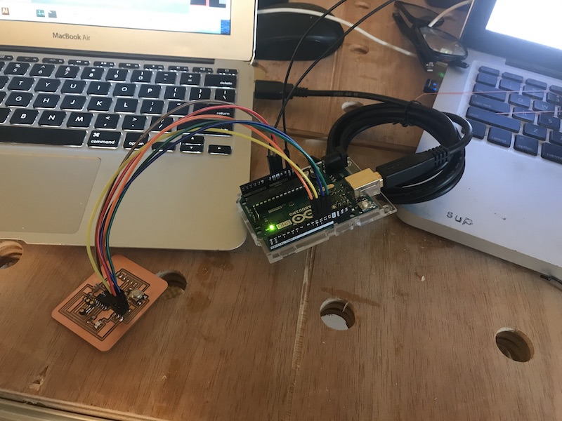
I started by reading this guide which gave a good into to using the arduinoISP I worked through this tutorial documenting using arduino as isp to program an attiny44. After loading the attiny family of boards into the arduino environment, setting the clock to an external 20hz, and selecting the attiny44 board i was able to send programs to the board. however though i didn’t get an error i wasn’t able to get the blink program to run. I’m going to keep on trouble shooting this later after getting more familiar with the arduino api.
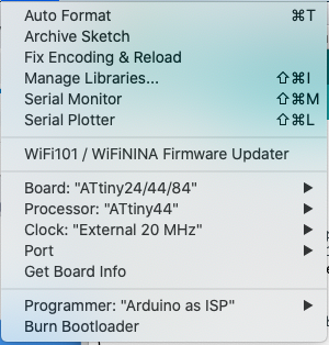
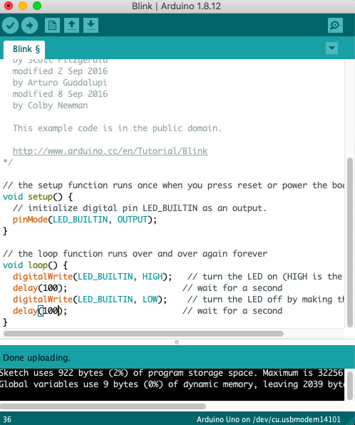
I revisited this and took another look at my blink example sketch. I realized that I didn’t have the correct pin for my LED specified. After changing this I was able to run my blink script successfully to my ATtiny44 target board the fabrication of which is documented in week 7. My wiring setup is the same as it is for my earlier attempt to program a programmer. Here are the settings in the arduino IDE that worked for programming it.
Arduino API
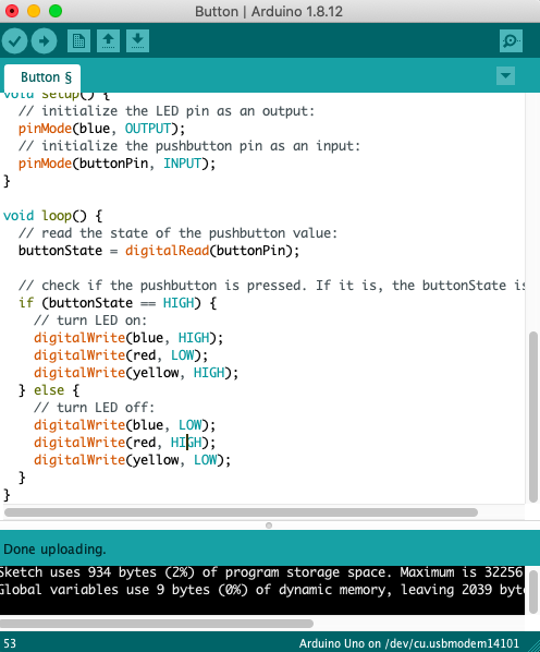
with the lab being closed i worked with the arduino and a breadboard to set up a simple input and output testing setup. The button is wired with a pull down resistor and the 3 leds are wired to separate data pins and a common ground. After checking my wiring with ‘blink’ I modified the ‘button’ sketch for a few variations.
ATtiny44 datasheet
I read through the data sheet for the attiny44a. When reading the data sheet the first thing I noticed is the pinout. This is something that is of course very important when designing and programming a board.
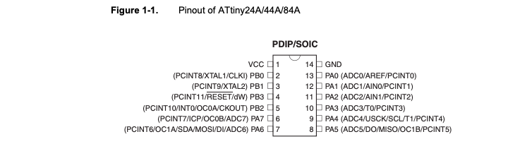
Generally I use pinout diagrams that include the arduino IDE pinouts as well as the ones for C programming, such as this one. One thing that is new to me is the more detailed explanation about how the pins differ. I wasn’t aware of the internal pull up resistors on pins 2 to 4 (PB0:PB3). There is also more detail on the reset input and the pulse length required for it to trigger.
The overview section of the data sheet was also interesting. One thing they mention is the ability of the user to control for power consumption over processing speed. While not relevant for my current projects, it is interesting to understand the broader context where this IC would be useful.
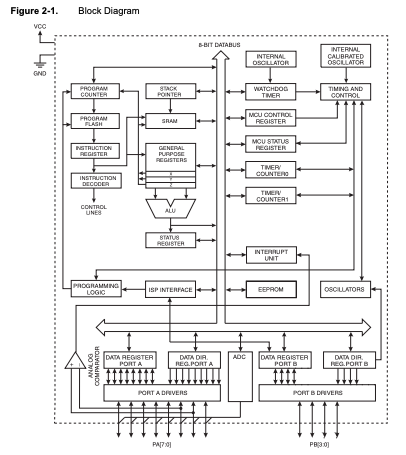
The diagram of the internal processing functions was interesting but definitely went over my head, however it was interesting to be able to place the parts I understand, such as the ISP interface and oscillators, in the context of the rest of the ICs processing registers. this also gives good information for understanding the pinout as specified at the bottom of the diagram and their relationships with the other elements in the IC.
Group Project
For our group assignment different students looked into and programmed different families, Nicolas has great documentation on programming the new 0-series and 1-series ATTiny. Significant differences between the two systems are:
ISP (AVR) -Advantages Very well documented on Fab Academy sites lots of programmers inexpensive inventory works well with arduino IDE -Disadvantages Need an existing programmer to make a programmer (became a significant problem in a pandemic with remote work) more pins for programming, more board space needed
AVR 0-series and 1-series- UPDI -Advantages only two pins needed to program, ground and UPDI onboard debugging (haven’t explored much but sounds exciting!) No need for existing programmer, just a USB serial IC -Disadvantages less documentation in Fab Academy sites, less local knowledge