3. Computer Aided design
The Three Ways I Use CAD
Making a One Off Design with No Parametric Features
If there is something I know I can capture in a single design I will often draw it quickly without any complex parametric relationships. I will have final dimensions on hand for everything including material thickness and sizes. I will end up with a useful model quickly that is not easy to modify.
Tools I use:
Hand drawing
Vectorworks
Sketchup
Inkscape
Illustrator
Fusion 360
Making a Drawing With One or Two Parametric Variables
Here I will make a drawing with variables for a few dimensions I would expect to adjust. A common example is a drawing for a project made out of sheet goods where I can adjust for stock thickness and the size of fasteners. This is the most common way I draw and offers a good compromise between speed and flexibility.
Tools I use:
Solidworks
Fusion360
Freecad
Creating a Complete Working Parametric Model
Here I create a model that I intend to use many times for many different applications. I can adjust both material sizes and the relevant dimensions with the linked features not requiring any manual adjustment. Creating one of these drawings requires a lot of attention to details and rigorous testing throughout the process. An example of this would be a laser cut box design that I want to use frequently with different materials and dimensions.
Tools I use
Fusion360
Freecad
Solidworks
Antimony(maybe)
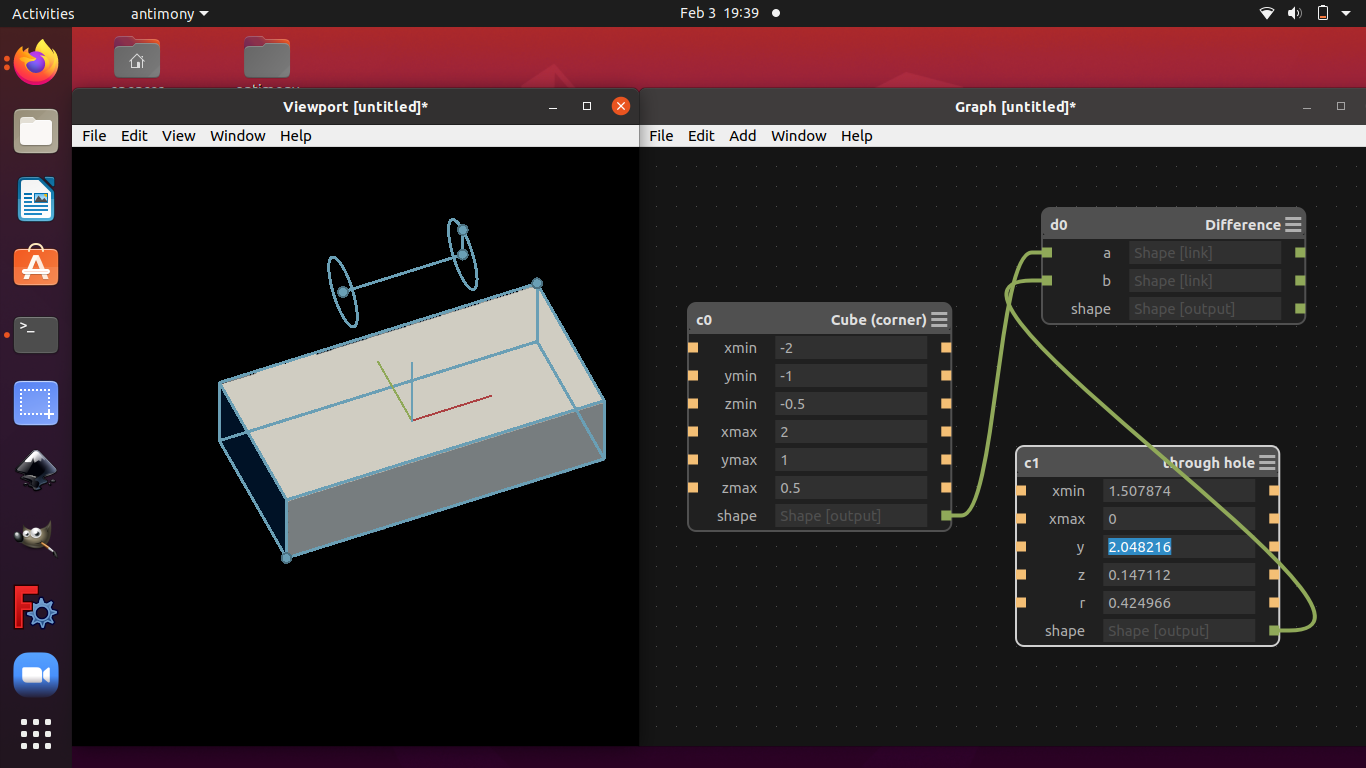
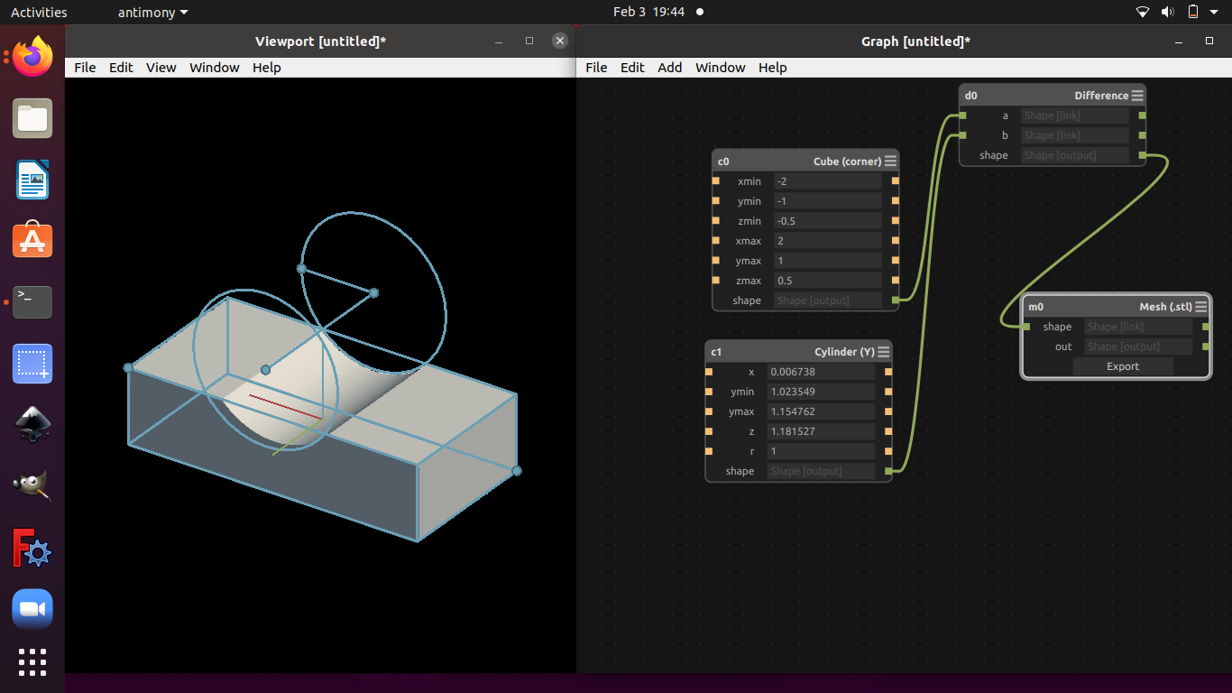
Installing and Using Antimony
I built the application for ubuntu following the instructions in the documentation. It went fine! Getting into the program was interesting, it is surprisingly intuitive. I was worried it would be more like OpenSCAD but it provides a really nice UI combined with easy access to the python scripting language behind it. I did some simple boolean subtraction of shapes, I could envision this being a really nice application for unconventation part generation. I’d like to find a practical use for this application and am going to keep pondering its uses. Overall I’m really impressed, and I’m going to spend some more time with the more unusual geometry options.
To run application:
./app/antimony
Freecad Basics
Solidworks Basics
xdesign Basics
What CAD software is for me?
In the past i have used a few software systems for design. Most of my time has been in Sketchup, Inkscape, Illustrator, and some in Fusion 360
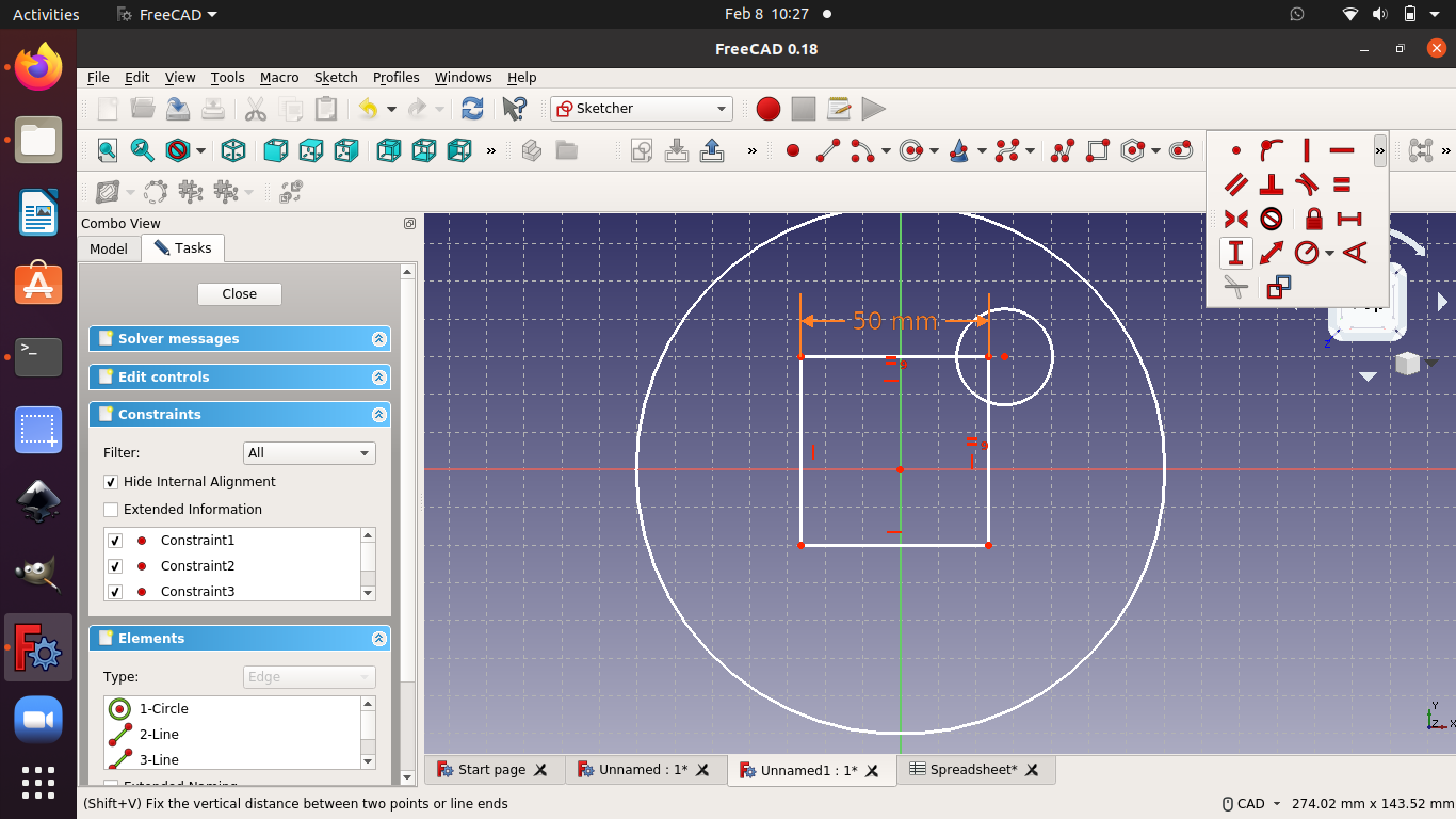
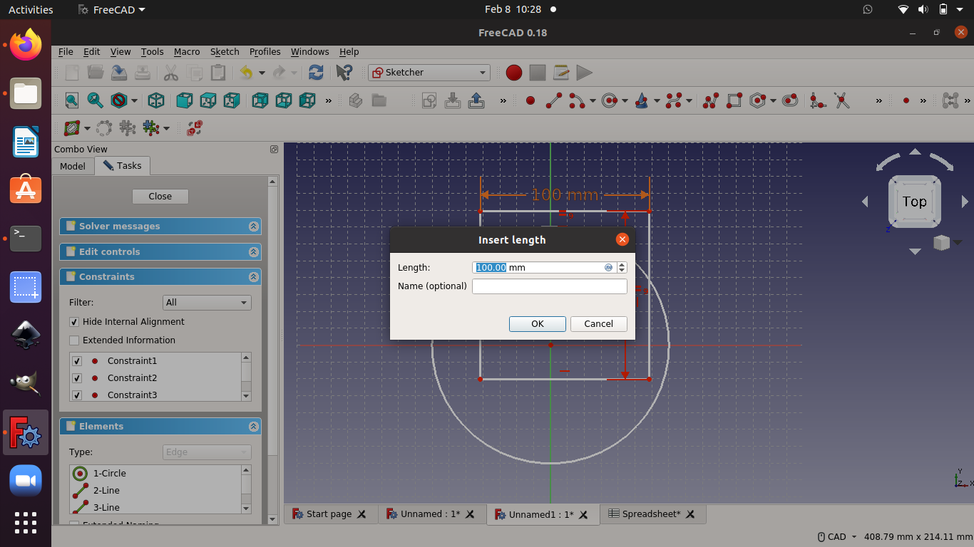
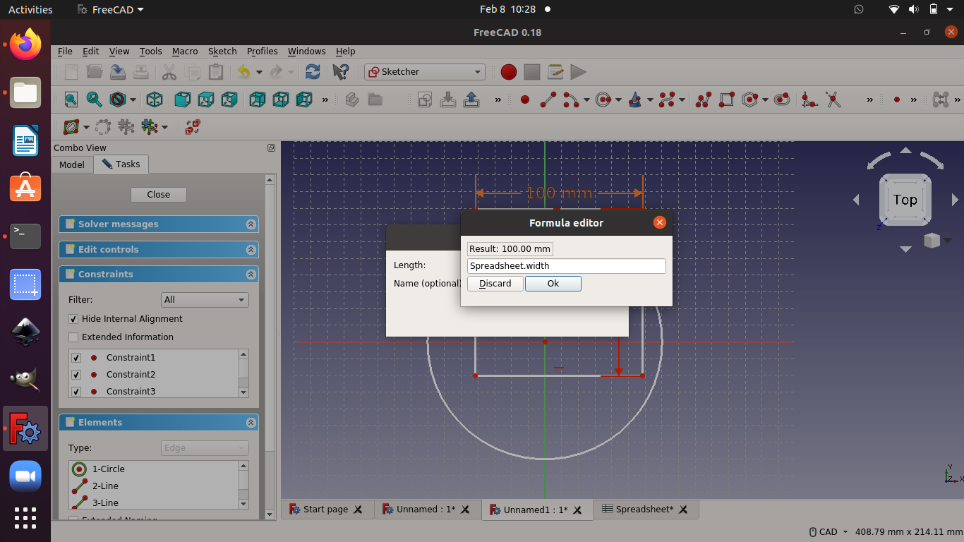
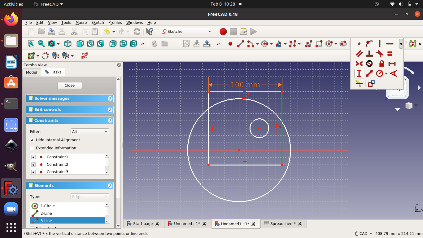
I played around with freecad a bit, I’m very impressed with how far it has come since the last time i used it. I was still struggling a bit with some of the features.
I’m planning on drawing up the frame of my final project in fusion 360. I worked through a tutorial on finger jointed boxes cut from sheet goods.
Tutorial on finger jointed boxes
This is a good starting point, however there are many features i will need to add to my design. These are the tooling size for creating dog bone fillets and joint fillets
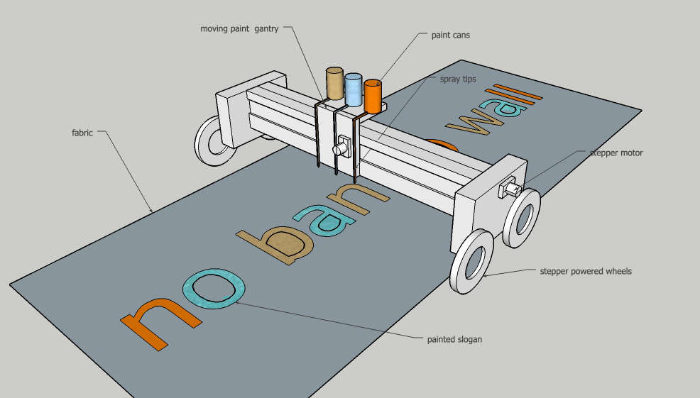
my basic design will consist of CNC cut boxes to make up the frame. rails for bearings will run along the center box and the wheels will be in the side boxes.
Outlining a design
My goal is to create the framework for the mechanicals for my project. As I figure out the sizes i need for my motors, controllers, and bearings i’ll adapt this drawing to accommodate them. to this end I’m going to draw it parametrically so i can adjust the height ,width, and length along with the number of joints.
One thing that is helpful is that i have a simple sketchup drawing I did for the week one assignment. even though it won’t be useful to pull geometry from it, it will be good for a rough guide for starting out
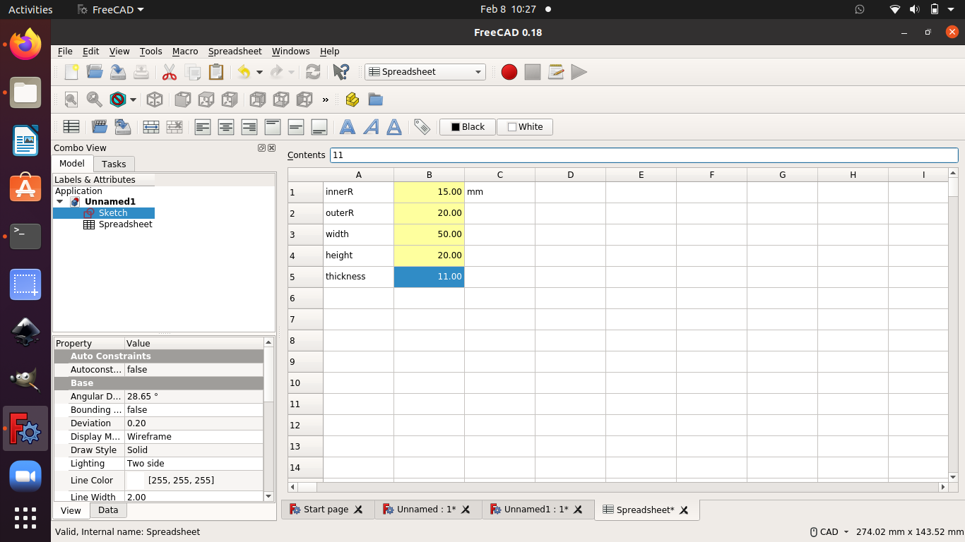
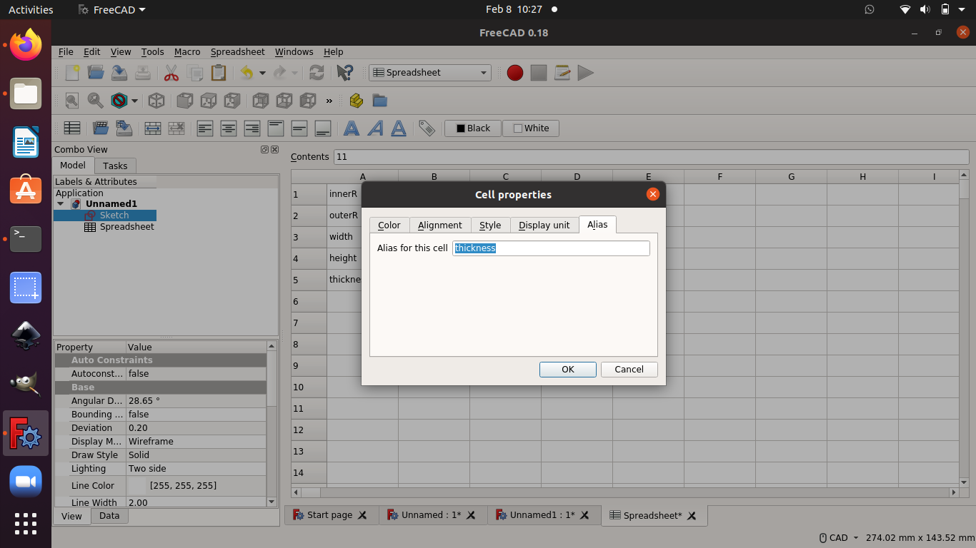
Making tables
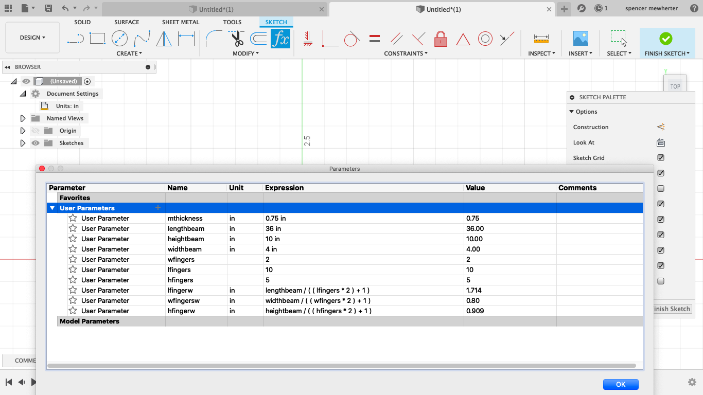
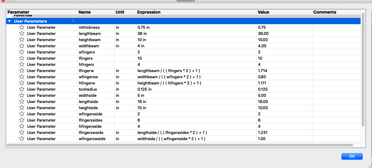
here is my parameter table for the center beam of my gantry. I added height, width, and length. Also there is a number of joints on each of them, along with a function that calculates the length of each finger and negative space
Sketching the design
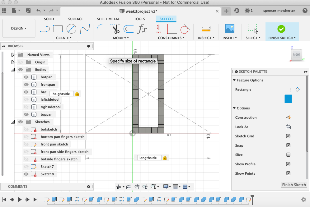
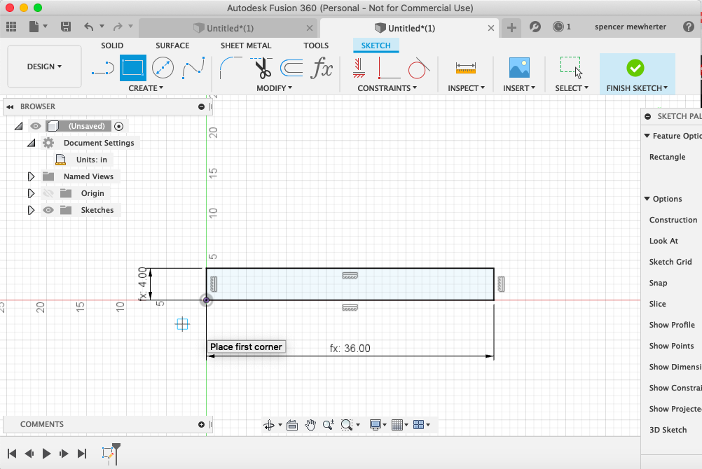
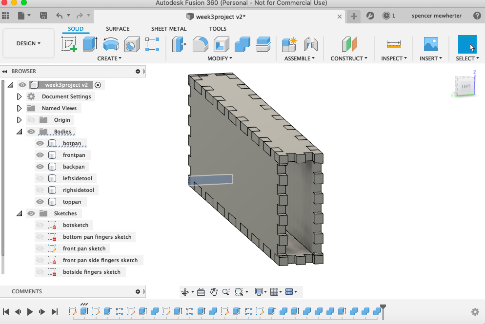
Creating these tables is interesting, since the final dimensions are far less important than the relationships between them. This is a little odd, but feels like an exciting way to draw. My first sketch is the lower panel of the center gantry. I add the width and length parameters and extrude it to the thickness of my material
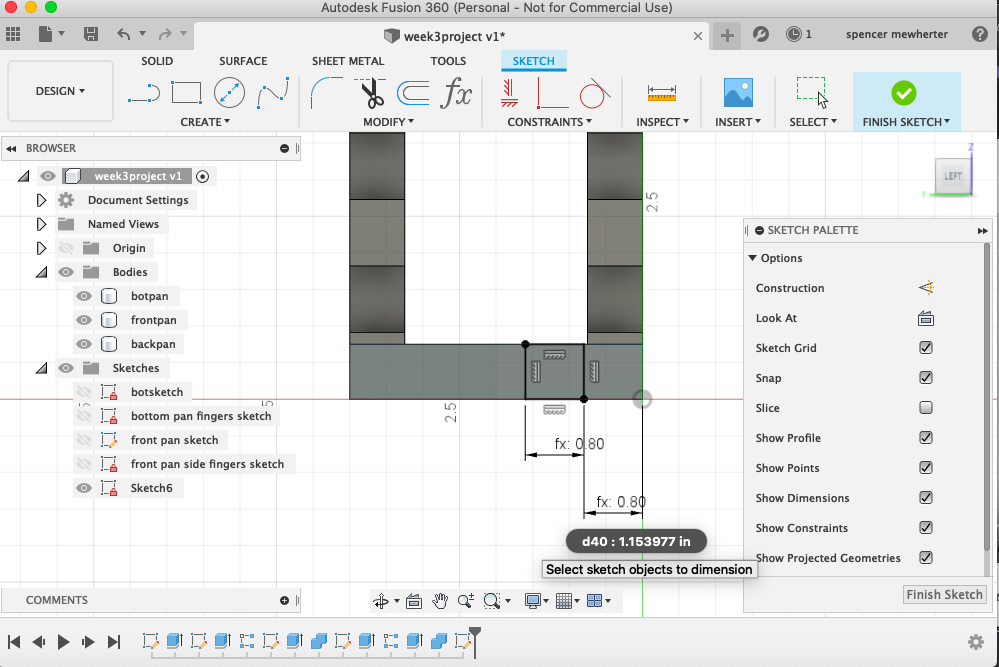
Drawing joints
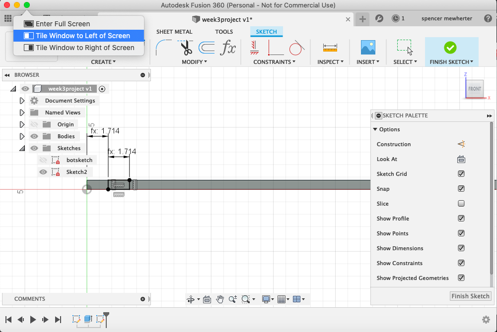
To add my joints i used the parametric table to pull the size of the fingers. This is a function of the length of the run and the number of joints. I use that for both the joint, a rectangle contained to the edges of the piece, and the relish distance of the joint
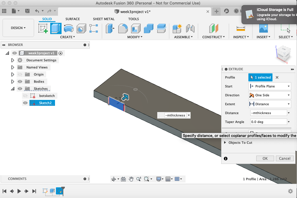
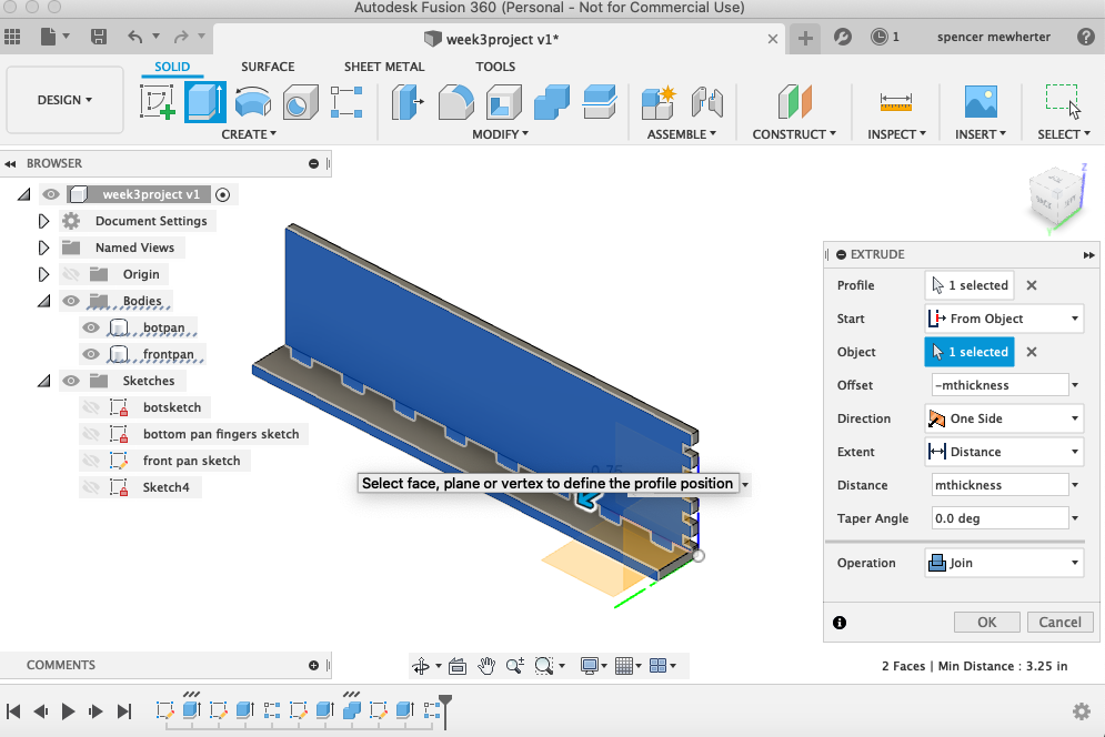
Adding features
Next i’m going to ‘cut’ the joint into the 3d panel to the thickness of the material. I always enjoy when the digital work flow reminds me of hand cut joinery layout.
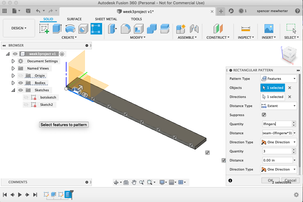
Copying features
Now I am copying the cut joint across the panel. This is another function of the distance and number of joints to figure the distance between them. This tool is a bit complicated and I want to spend more time working with it.
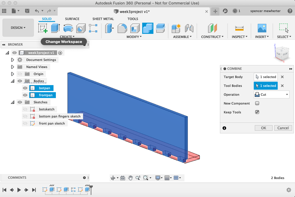
Second panel
Now I’m adding a second panel and using a boolean operation to cut the joints into the newly created panel. Once again the large number of options in Fusion can be overwhelming. important for what I’m working on is to remember to check the ‘keep tools’ box
Copying parts
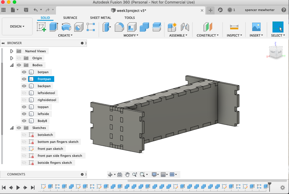
One counterintuitive thing i learned from the tutorial was to use the extrude tool to copy faces across the drawing. it turns out it’s a very effective way to create copies quickly
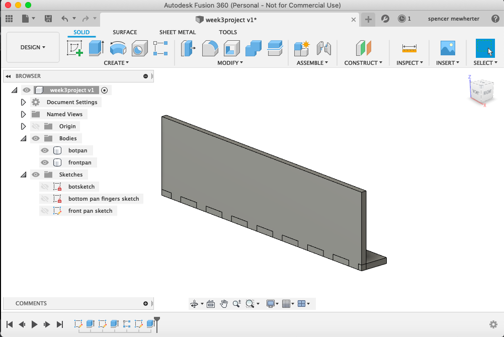
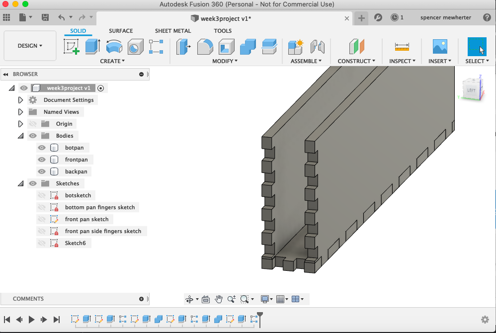
rinse and repeat
Now that i have a process for creating joints and moving parts around, it’s just a matter of repeating and copying parts around my drawing
Adding to the table
to expand my project i need to add more features to my table these are parameters for the end boxes of my gantry. These will hold the wheels and stepper motors for driving them. all things that aren’t designed yet
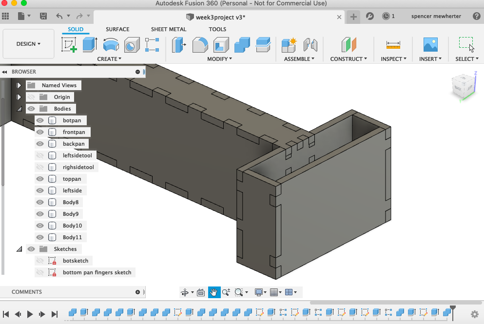
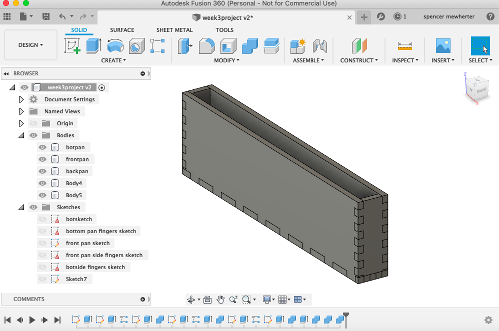
Additional systems
Here is a sketch for a 3 point rectangle centered on the gantry frame, I’m pulling the parameters for my table. This will effect both sides of the project. though i would like the option at some point to define the two sides separately. The process of adding joints and tabs is the same as it was before, but with different variables.
one thing i’ve noticed is how hard it is to keep my table organized even for such a simple project. I’d like to learn a few more organizational tricks for this.