7. Electronics design
I decided to work on two different boards this week. one was based on the tutorial [] that used the attiny45 programmer and the other was based on the UPDI programmer I built last week. One lesson i learned was to carefully check the shops inventory before starting a design! Learning more about reading IC data sheets will also be an important skil to learn.
Finding Parts
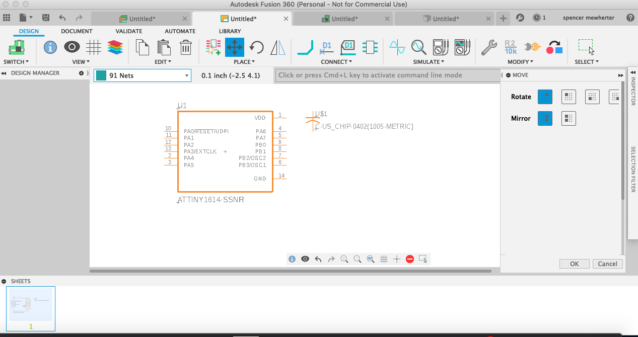
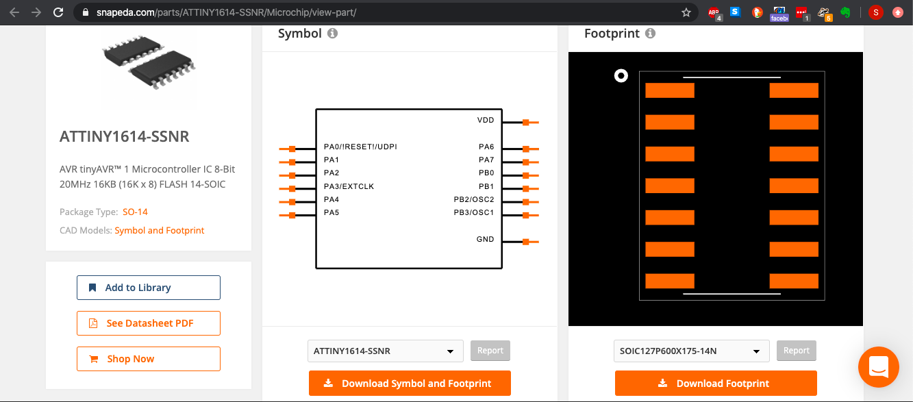
I started by working on a board based on the Attiny1614. I was supprised how hard it was to find the part in an online library. I ended up having some luck with Snapdea which had a really nice copy. some of my issues were definitely based on my not using the stand alone version of Eagle.
Learning Eagle
I started by working through the Fab Academy tutorial This got me heading in the right direction! It was good having a design to work from and add elements to. Working through the tutorial went well overall. I was using Eagle/fusion 360 for most of the work. While I like the idea of being able to draw PCBs in fusion, I ended up installing and using Eagle for exporting the design. There is enough different with Eagle in Fusion 360 to make finding and following tutorials frustrating. Importing the fab Library went well. I also removed most of the other part libraries as well. This feels like it will be a really useful feature moving forward.
My board with a LED and button added. I also had to swap out the six pin header with one with the correct profile from the fab library. The other one had larger pads that didn’t allow for traces under it.
Building a Board
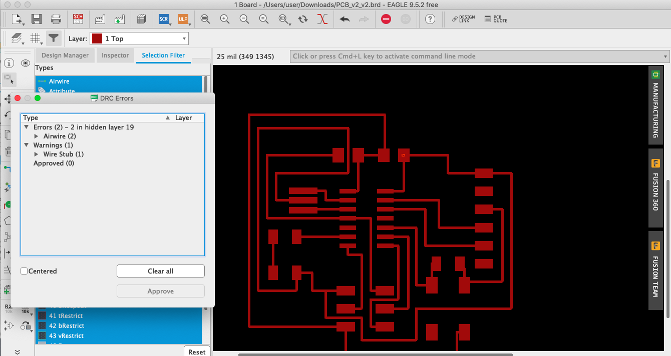
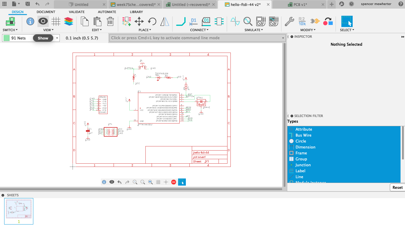
Traces completed! At this point i moved into stand alone Eagle, fortunately this was pretty painless to move everything over. Doing the traces was fun! once all the airwires are made it does really feel like a puzzle. I ran the script to check it. I had two errors for remaining airwires. They were both just connecting the common sides of the switch pad so i felt fine ignoring them.
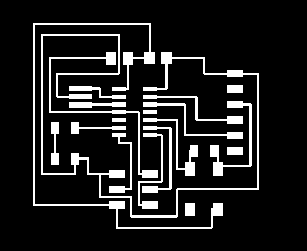
I then exported a png and opened it in GIMP. Here I created another layer for the cutout. I feel like i left more space then necessary around my board, but it was a pretty painless process to get this done.
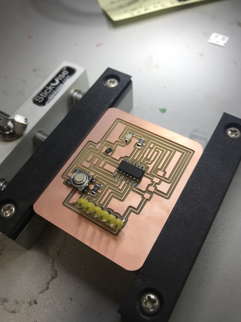
PCB Production on the Mill
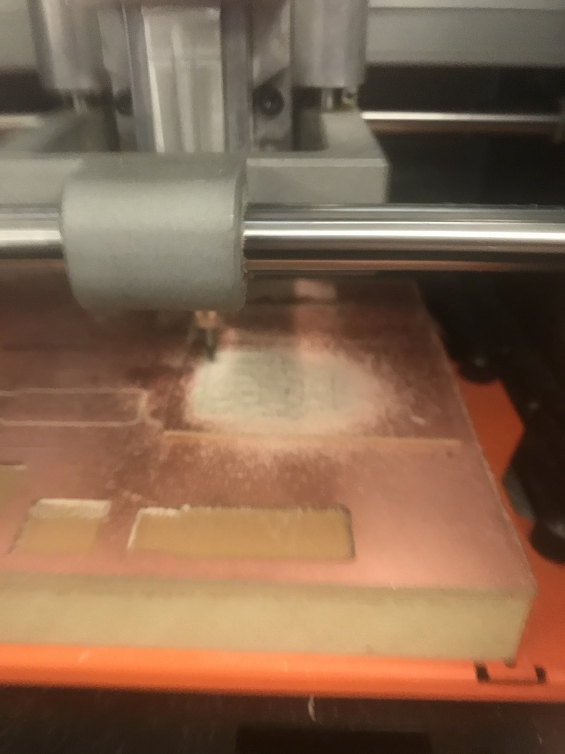
I milled this board on the Roland in our shop. I was really concerned about scale issues, but fortunately I got lucky and it cut fine. It’s really disorienting to be milling based off of a PNG file. I’m used to the world of vector files so I was getting really nervous about how to fix the scale if there was an issue. In the review Neil mentioned that this is mostly an issue with macs with a retina display. Seems like i should be in the clear with my 2014 macbook.

Both cut files worked great! the first thing I did was lay the IC on the board to check the scale. It looked great.
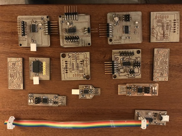
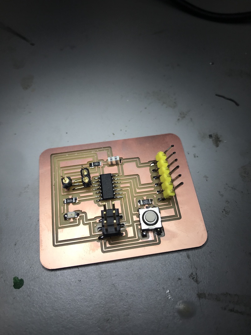
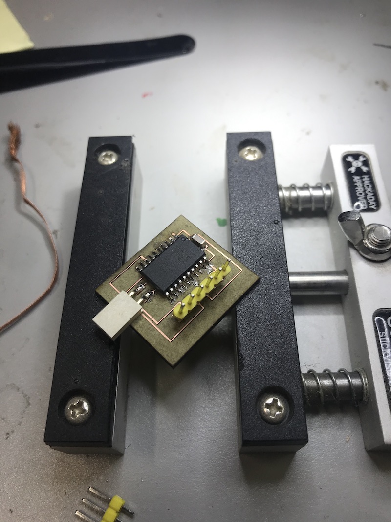
I then stuffed the board. He are both boards I made this week with parts. one on the fiber laser and one on the mill.
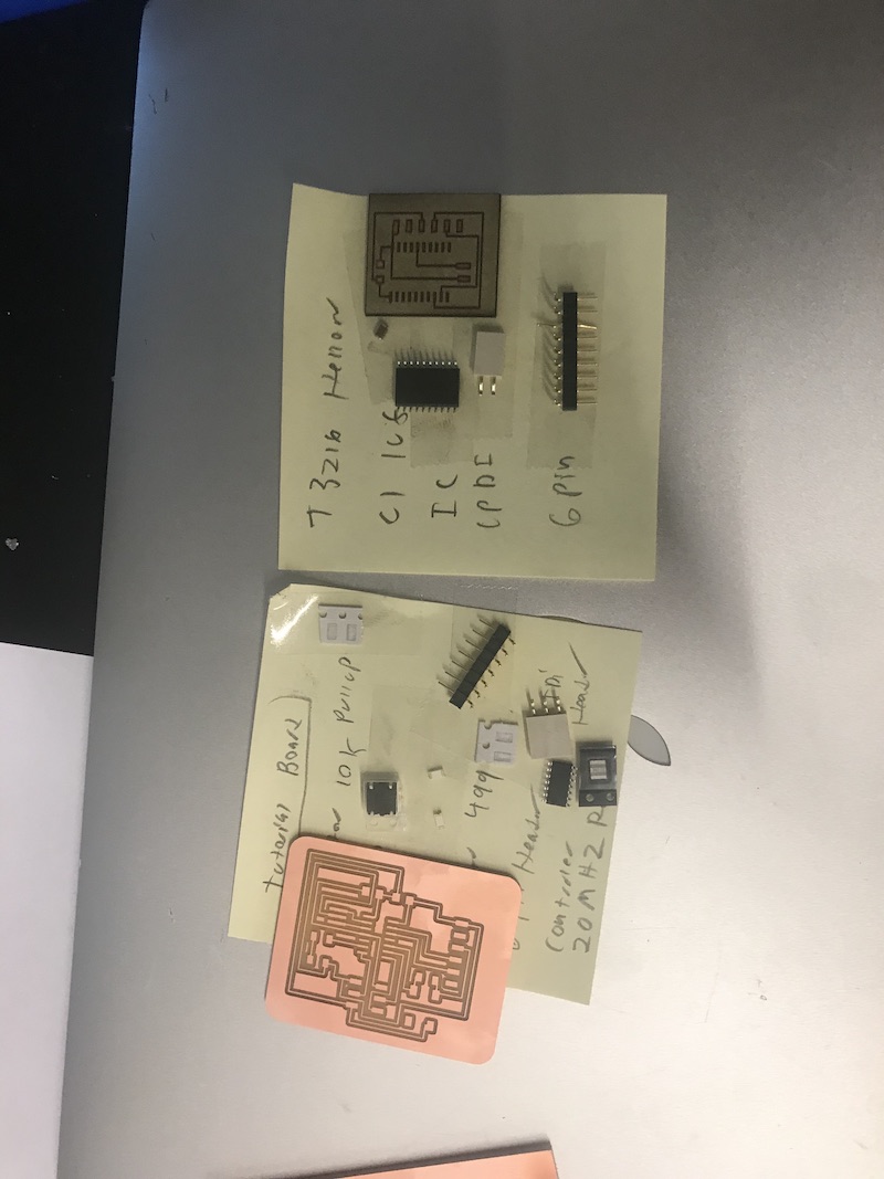
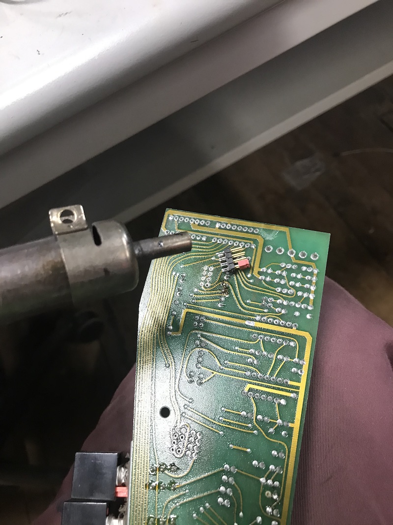
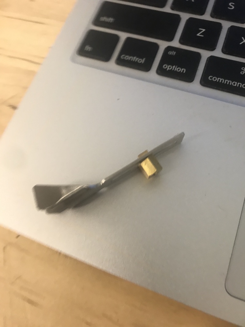
I realized that I forgot to grab a 2x3 header before heading back to my shop from the lab! Fortunately I was able to harvest one from an old board laying in a pile of junk with a heat gun.
Using the Fiber Laser
I also experimented with our fiber laser for making a hello.t3216. I’m hoping to keep up with both the ICP and the UPDI boards and learn both. I found the fiber laser a complete pleasure to use. We have a trotec speedy 400 flex which has both fiber and CO2 lasers in it.
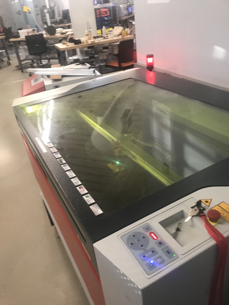
at first i was concerned and confused that it wasn’t engraving! My classmate helped me and pointed out that i was using the focusing dropper for the wrong focal length (thanks Nickolas)
the board all done. One think I didn’t think about was the lack of ground area. there is something of a natural ground pour when routing and using mods. However a file like this will produce only the traces after rastering.
Group Work Observing an Operational Board
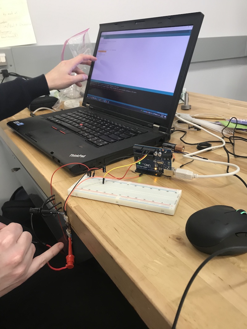
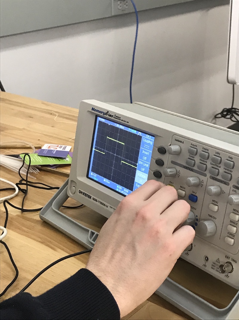
For our group project we looked at an operational hello LED board. We were able to hook an oscilloscope to the led to read the frequency of the blinks and check that it was the same as in the program. We also hooked in into the inputs when programing the board. while not readable we could see the data output of the programmer heading to the board