4. Computer controlled cutting
Vinyl cutting time!
I cut a sticker! to demonstrate workflow from inkscape to a roland I decided to use inkscape to print run the machine.
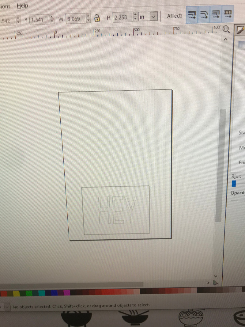
I drew a quick pattern in inkscape, one thing i always like to do is to draw a bounding box around my work. This is a habit i do for all kinds of work, and i typically document the size of the box in the file name. This allows for a quick check of scale after moving across programs. In this case i’m not worried about scale, but it will give me a good starting point when weeding.
opening the print dialogue shows the the roland is connected. there are two important things to do in the setup, one is to rotate the drawing 90 degrees, and the other is to pull sizes from the machine.
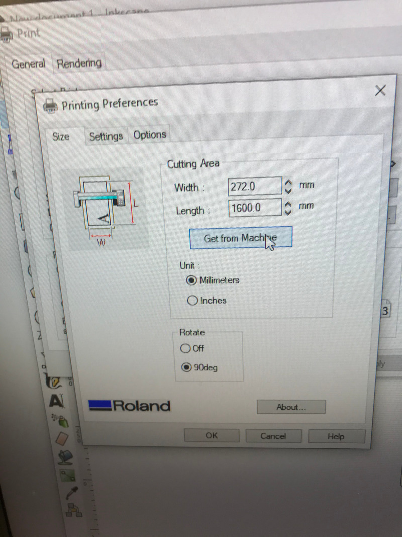
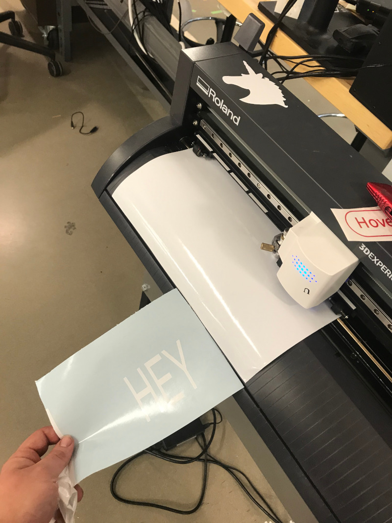
cutout fine! one tricky thing about printing from inkscape is that the file rotates.
how wide is the laser?
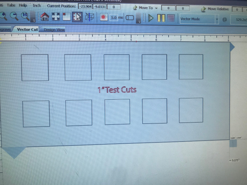
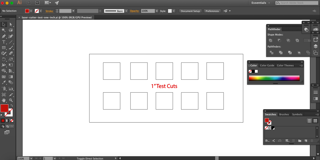
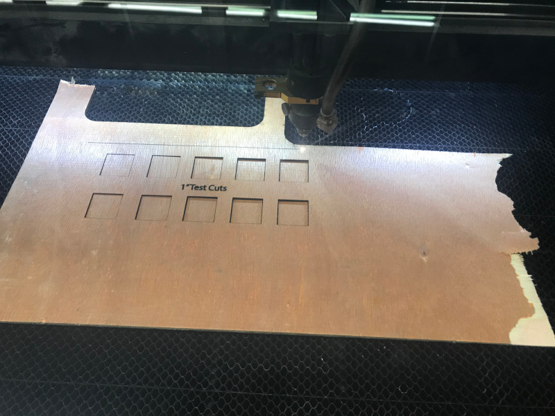
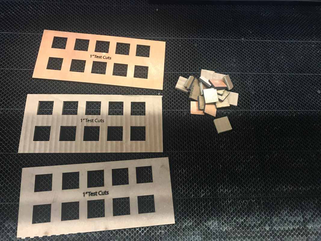
When characterizing the laser cutter i drew a simple pattern of one inch squares. I characterized a full spectrum laser in a local markerspace i have access to. I then measured out all of the squares. one thing that was really confusing was that the laser seemed to be cutting at almost exactly 1.00”. That didn’t make any sense since the laser clearly had a kerf! When I took a closer look i saw that I had a scale issue happening between the inkscape file and the full spectrum driver making the squares in the file .992” hmmmm that won’t do! but at least i can calculate the kerf and caught a software issue before i tried to make my construction kit.
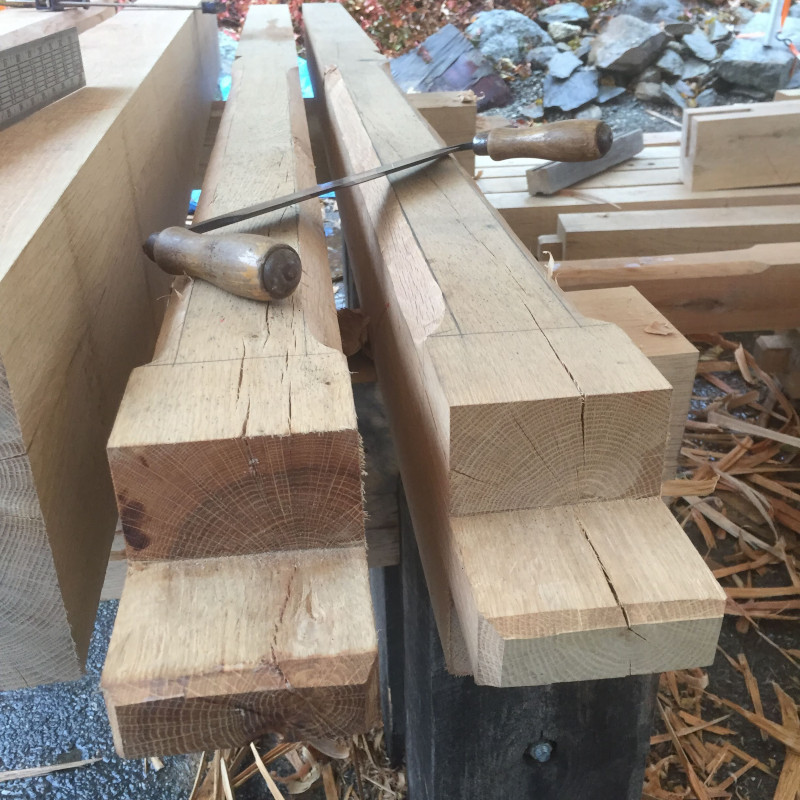
Timberframe construction kit
for my construction kit i wanted to do something that reflects my work doing timber framing. I envision this as a simple educational tool that allows students to play around with joinery concepts. to allow them to be ‘cut’ to custom sizes I want there to be perforations for lengths and mortises.
Design
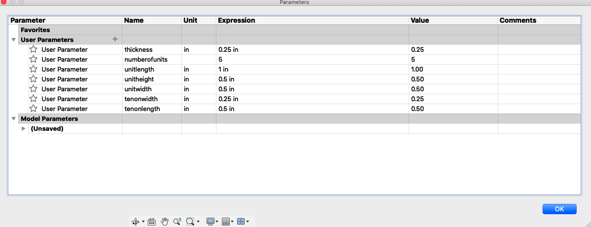
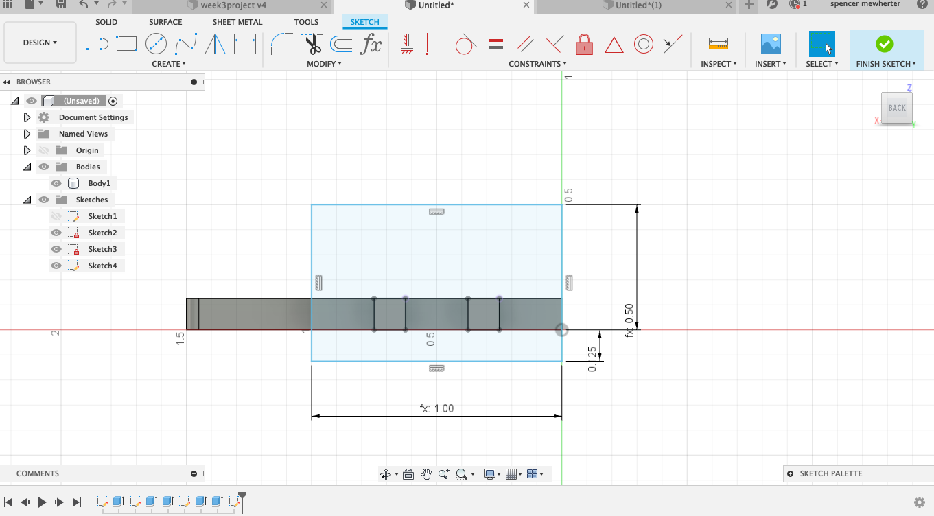
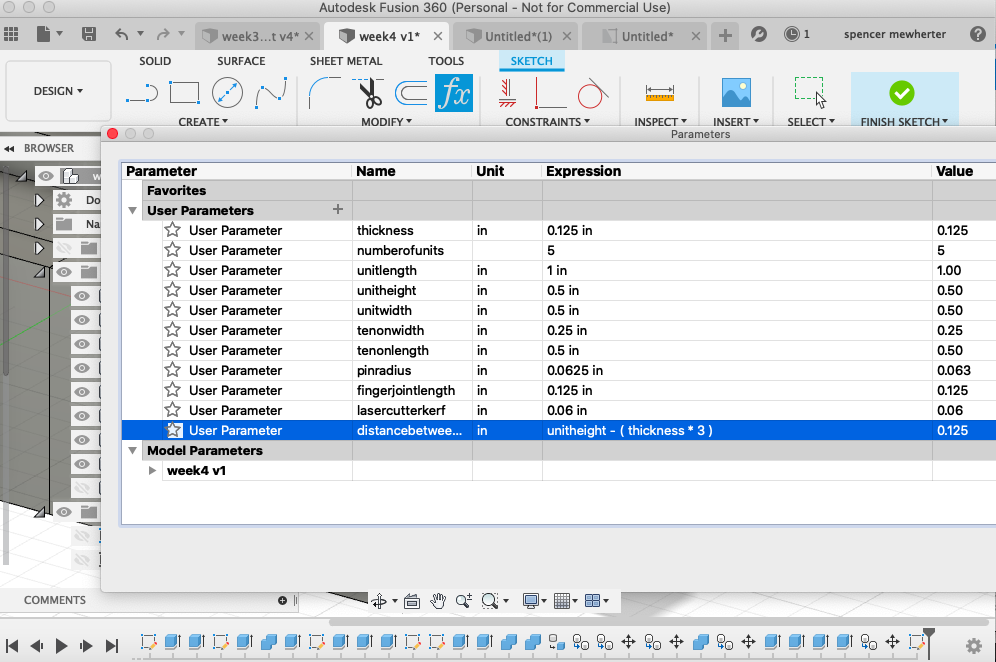
This turned out to be a pretty tricky design to get right! besides the kerf for the laser, I also wanted to make my design adaptable for different thickness of material and adjustable for height and width. I started with filling out my parameter table.
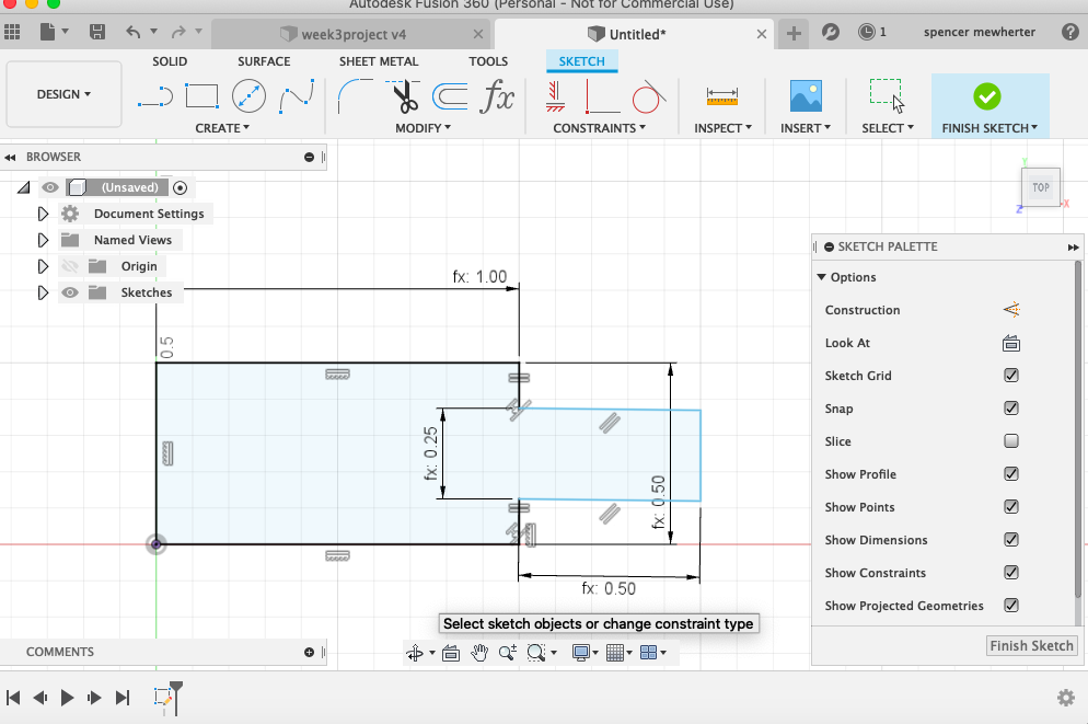
On to the first sketch. Here I’m adding geometry for the dimensions i created in my table. Though this is a pretty simple design with only two parts its tricky to keep all the dependancies in my head. In the future I’d like to keep changing my parameters as I draw to test each drawing and extrusion
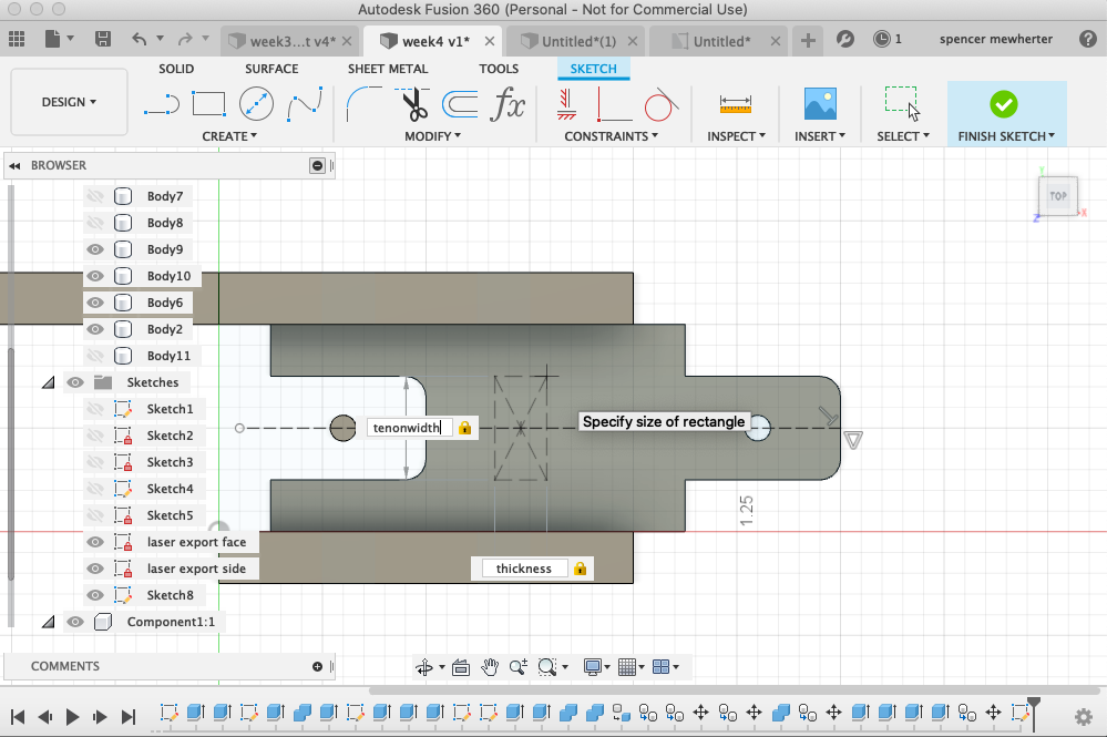
into 3d space! now I can make the fingers on the side and add the sides of the beams
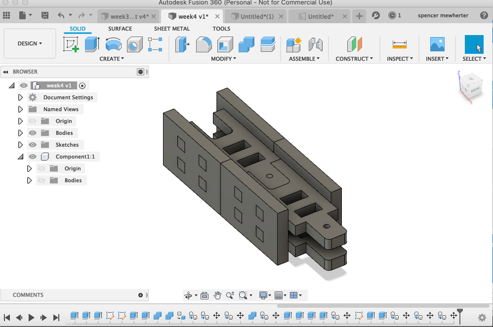
I’ve updated the parameter tables for more features. Moving into 3d space creates more opportunities to get my geometry confused.
and here is my final design!
Exporting for laser
Time to cut it out for real! I adjusted my parameter table for my material, in this case some scrap card stock .120” thick. Changing this not only adjusts the width of the slots but also the distance between the two mortises.
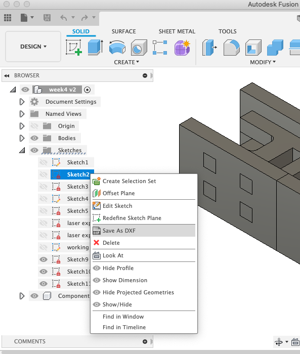
I then exported my sketches as dxf files. Using the option on the sketch sidebar. In the future I will use the toolpathing options to export to dxf.
I did more toolpath work in illustrator. Since I’m both cutting and etching in this design I need to define these by hand. This is time consuming so I’d like to find a way to streamline it. I then used the full spectrum laser cutter software to set different power settings for each color in the design referencing my test cut pattern. for this material with a nominal 80 watt tube it was 15% power 100% speed to etch, 35% power 100% speed for the cutout.
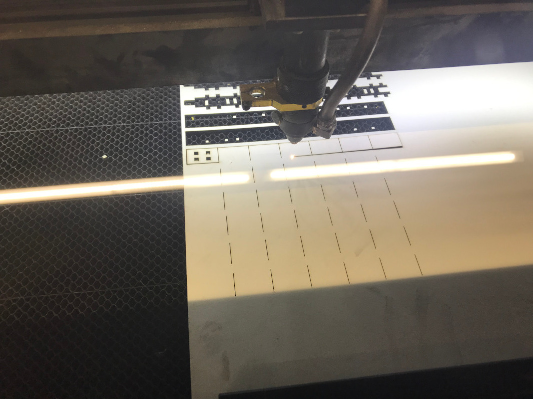
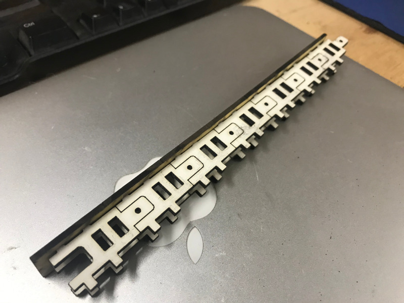
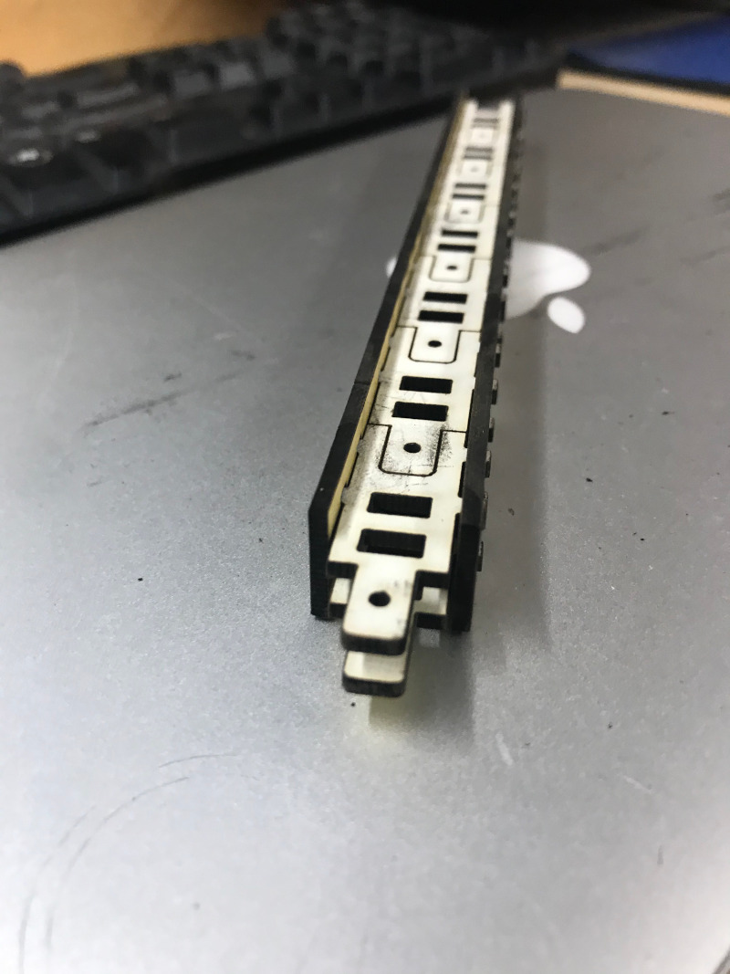
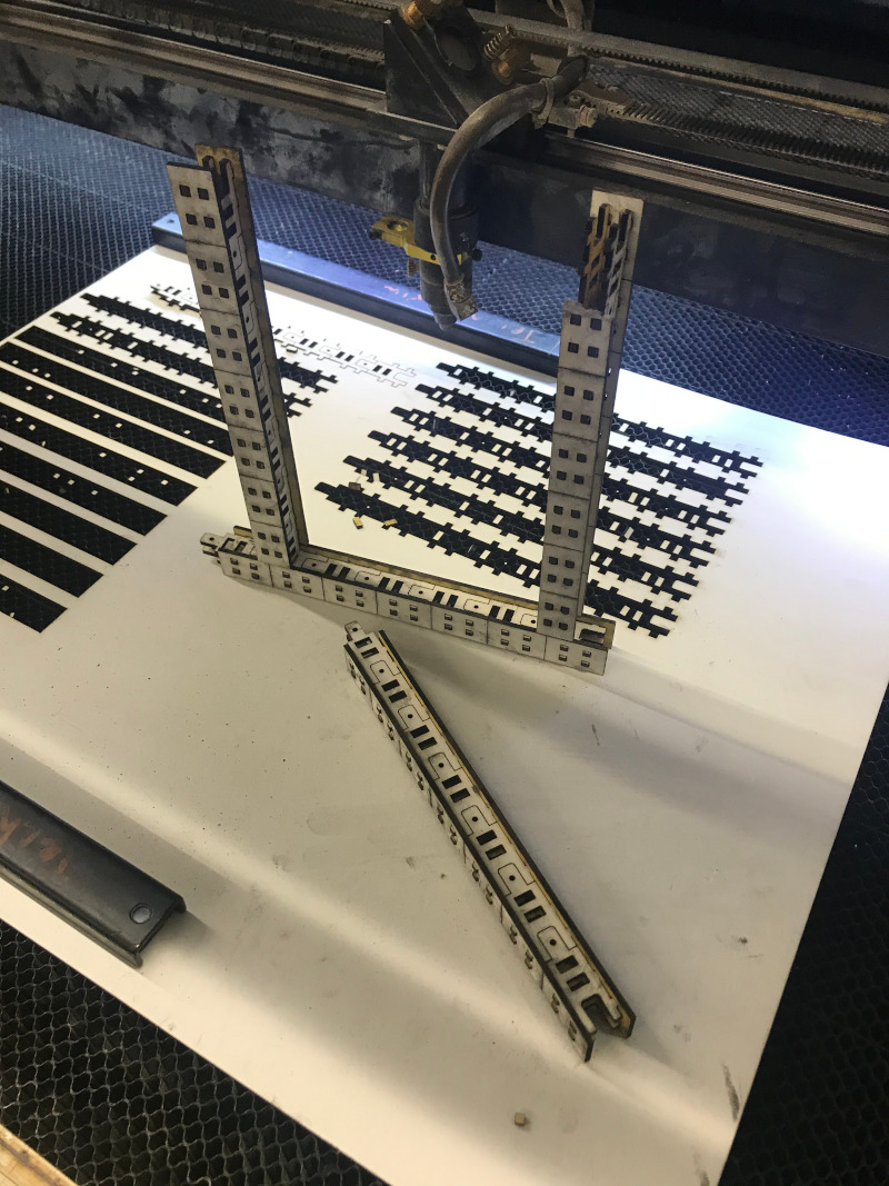
cut out and assembled