This week, we're essentially picking up where we left off on week 4 with electronics production.
We covered topics such as:
- basic components
- fundamentals of electronics
- circuit design
- reading a datasheet
- PCB layout and more!
TIP
This inventory on the FabAcademy website is a great place to find exact part numbers for things that are likely to be available in the lab.
Back in week 4, I picked the UPDI programmer as the board I wanted to manufacture. In order to be able to choice. I am feeling even more confident in that choice this week: the new 0-series and 1-series ATTiny sound like really interesting parts to explore. To do that, though, we'll need a working programmer, and that is turning out to be a challenge...
# Class notes
I have a decent (but distant!) background in electronics already so most components were familiar, but here are some tidbits that jumped out as things to brush up on because I've forgotten most of the useful details:
- Zener diodes: used as a clamp (will start conducting backwards when voltage goes far enough below zero; use it backwards to tie an MCU input pin to ground, via a current limiting resistor; if your input voltage goes too high, the Zener will start conducting backwards, grounding your dangerous input) NB: For this application, a Schottky diode might be better?
- MOSFET: voltage on the gate controls current flow between source and drain. Gate voltage could be varied continuously but is usually full on or off (or PWMed?) instead to avoid dissipating power in the MOSFET
- OpAmp: amplifiers, filters, etc. The fundamental brick of many ICs but not that useful directly anymore
- Book recommendation: The Art Of Electronics
# Group assignment
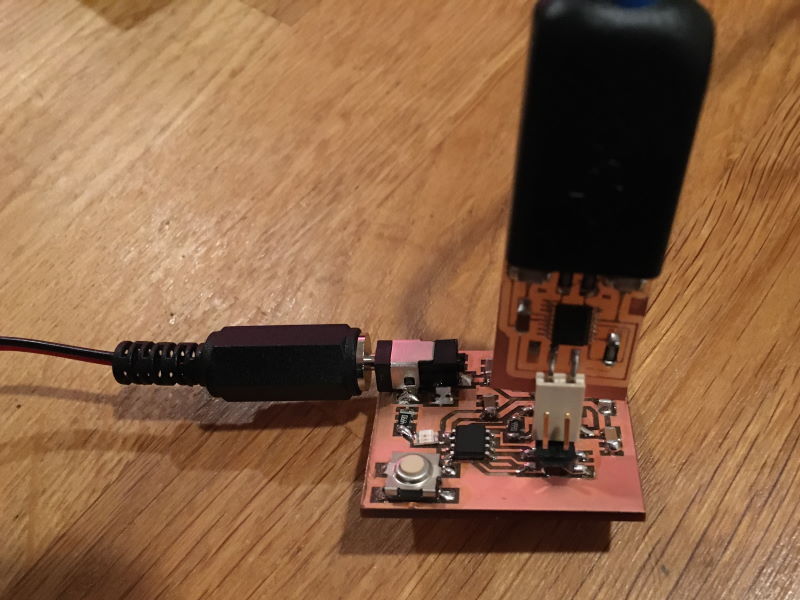
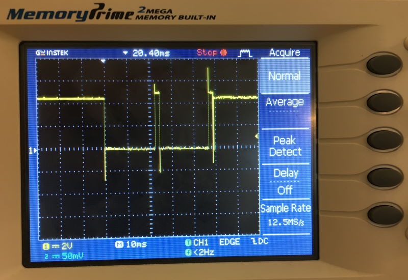
This week's group assignment was to observe the operation of a microcontroller based PCB. Since I was struggling to get my UPDI programmer working, I chose to verify that distant memories of how to correctly use an oscilloscope from college were still valid (I remember shamefully little, especially considering I even own an oscilloscope!).
Since I had already designed and manufactured a very simple breakout board for an ATTiny412 over the past few days (more on that in the individual assignment below), this made a perfect test bed. I wired up an LED to an output pin (in the kludgiest way possible!) and uploaded an extremely simple blink program.
void setup() {
  pinMode(2, OUTPUT);
}

void loop() {
  digitalWrite(2, HIGH);
  delay(10);
  digitalWrite(2, LOW);
  delay(100);
}
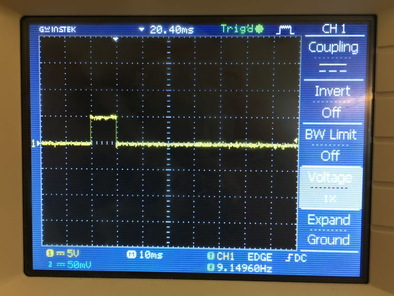
We connected the probe between the ouput pin and ground on a very kludgy prototype ATTiny412 board I had made after week 4:
and we were able to see the result one might expect: 5V square pulses at regular intervals matching the delay() value in the code.
# Individual assignment
This week's individual assigment was to redraw a basic PCB with at least a button and an LED, validate that it passes design rules, make it and test it.
Since, as detailled in week 4, I already have some exposure to designing PCBs, I decided to explore two challenges:
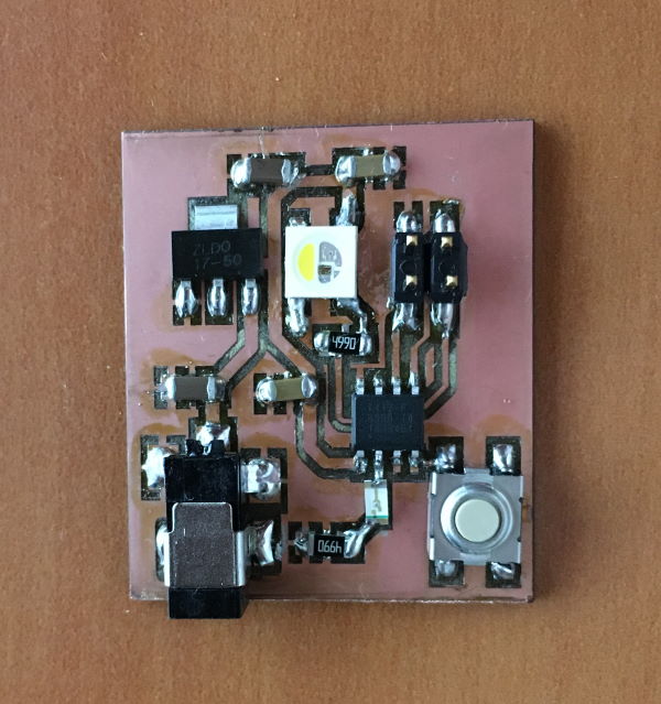
- making a breakout board for the Series-1 ATTiny (specifically an ATTiny412) instead of some of the more standard designs, and adding some more interesting components to it
- manufacturing the PCB on our fiber laser cutter instead of the mill, to test out the design rules there
# Requirements
I decided on the following specs for my board:
- ATTiny412: this extremely small IC still has a bunch of interesting features I want to explore in the future
- battery operated; this meant some sort of regulator would be needed
- plug and play: no more fiddling with jumper wires to connect to a power source
- one button for some sort of input
- one basic LED for simple output (with its corresponding current limiting resistor)
- one adressable RGB LED for future fun (I salvaged a WS2812B from a strip I had on hand)
- a breakout for UPDI connection and for the remaining IO pins, if any
# Schematic design
I selected CircuitMaker as my E-CAD tool of choice, for a bunch of reasons:
- it's free (as in beer, not speech, unfortunately)
- being cloud based, it has a nice platform and community for sharing up to date components
- it's based on Altium Designer, which seems to be popular as a professional product
- its UI and workflows seem to be a little easier to grasp than Eagle, and it has good documentation
- it seems to be gaining traction quickly in the DIY community, perhaps based on the factors above
- and finally, working at Solidworks I hope to use Solidworks PCB at some point... which is based on Altium Designer
I had left off week 4 with a bunch of links to breakout boards for the ATTiny412 to use as inspiration; using those and the ATTiny412 datasheet and various Application Notes as starting points, I came up with this schematic:
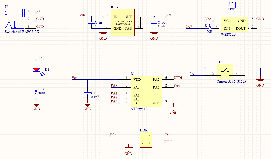
I probably went overboard on the capacitors by including both the ones suggested by the NCP1117 regulator and a decoupling capacitor for the MCU, as well as one for the WS2812B LED, but it probably can't hurt to be too careful!
In hindsight, I also wish I had thought of some sort of keying for the 2x2 jumper block so that the UPDI can't be connected in reverse (or some sort of reverse polarity detection) but that will have to be an improvement for a future revision.
# PCB design
With the circuit designed, it was time to move on to the PCB design. Here, I decided to go with an approach that I've only started exploring for my last couple of designs: using a ground plane rather than individual traces (and a power plane if possible, though this single layer design precludes having both). While we didn't quite cover this in class yet, I like this approach because it virtually eliminates routing half the pins on a significant amount of two terminal components.
Combined with the low pin count on the ATTiny412, this routing step that I usually dread (because auto-routers usually don't do a very good job of single sided boards and crossing traces is impossible without vias or using 0 Ohm resistors to "bridge" over existing traces) actually turned out to be surprisingly easy:
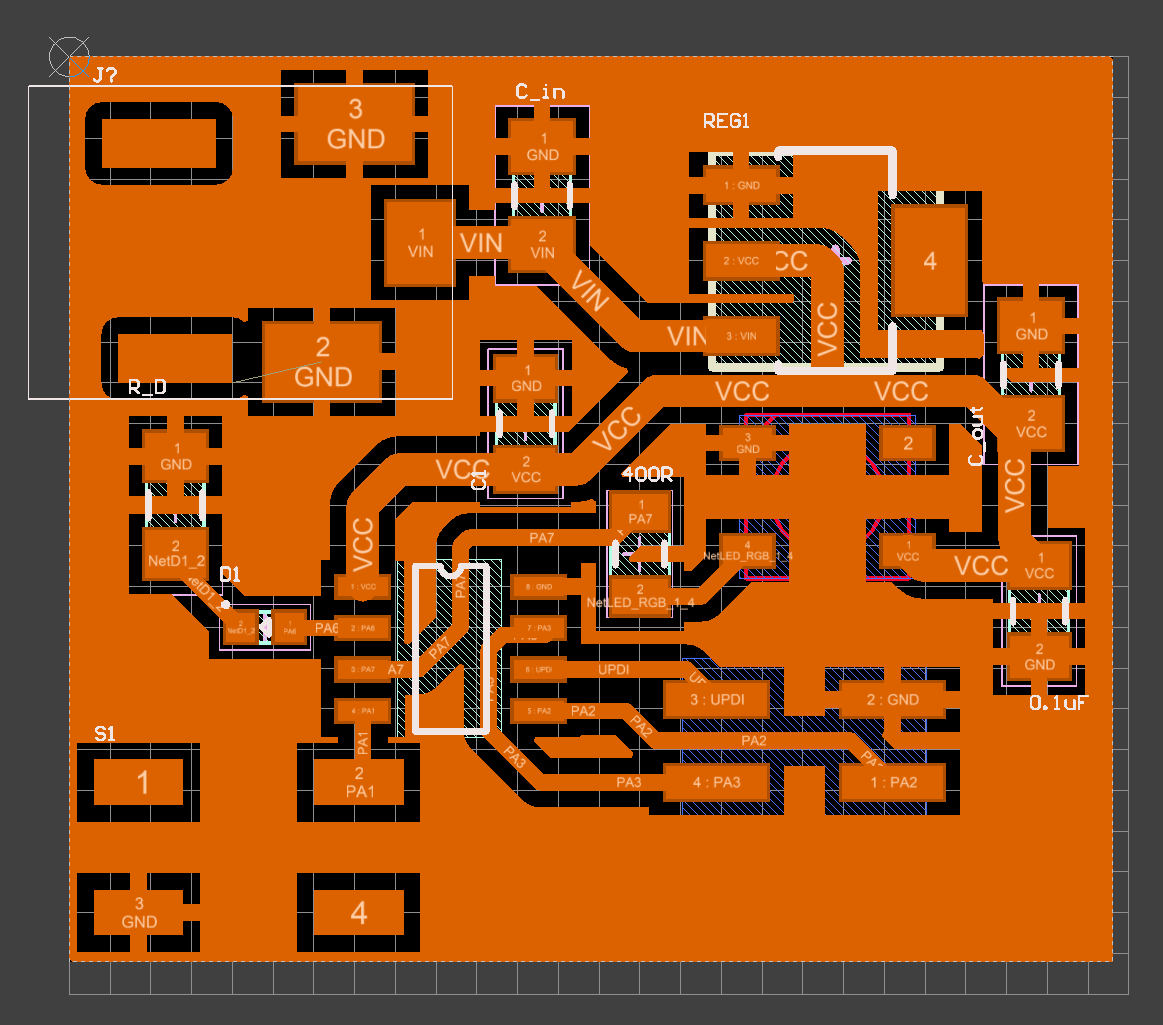
As can be seen above, the signal traces are kept small enough to route under ICs in places, while the power traces are a little wider as a precaution. This isn't actually all that useful here but I have some experience powering a bunch of adressable LEDs and they can draw a surprising amount of current!
I ended up mostly eyeballing the right values for trace widths that would be manufacturable with the laser cutter and landing on these settings in CircuitMaker's design rules system:
# CAM
Oh boy, this step was a pain! You would think taking a design from CircuitMaker to the laser cutter would be trivial, right? After all there's not really a need to figure out a cutpath since we'll be rastering away the coppper as if it were an image.
But of course, we'll need a PNG of our traces... and that turned out to be problematic (perhaps through my own incompetence!).
I could not figure out a way to have CircuitMaker export a PNG, or any similar format. There are options to print your design but these seem to come pre-set to show too many layers for our needs and I could not make sense of them, so I ended up exporter as Gerber, thinking that a software solution to open that and generate a PNG had to be simple.
It was definitely not.
After several false starts with terrible proprietary software, online Gerber viewers that choked on simple designs or were "free" until you actually needed to do anything useful, etc., I settled on Gerbv. This actually turned out to work quite nicely, and let me change the colors in a way that would make final setup in Illustrator and JobControl for our Trotec easier.
The right process ended up being something like this:
- make a note of your exact board size in CircuitMaker
- export to Gerber (add mechanical layers in Gerber export in CircuitMaker, I exported in millimeters in 4:3 format for simplicity but any format seems to work)
- In Gerbv: show the layers you want (likely just .GTL, maybe some cutout layers if you need cuts)
- change background color to black, make traces layer white, make any cutout layers red, and always set opacity to full for all colors!
- Set Gerbv to fullscreen mode, zoom to fit
- save as a png
- crop the png to the board (it will have a bunch of dead space around it)
- Open in Illustrator
- import PNG, resize to actual board size!
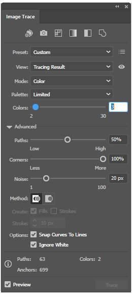
- Image trace the png with the settings below
- create red polygon for board cut(s), copy polygon, increase width, make black for copper removal
- repeat step above for any hole cutting needed
- use 2.85" flexx lens
- set JobControl to 2.85"
- use correct focusing tool
- run the job!
More on that horrible resizing step in the Challenges section below!
# Manufacturing
For manufacturing, I decided to experiment with our fiber laser cutter (a Trotec Speedy 400). I started from this extremely helpful writeup from past students and tweaked the settings from there.
I arrived at these settings:
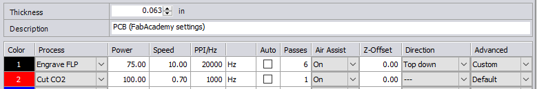
A couple of things to note here:
- I went down to a single pass for the CO2 cut of the outline; single passes should produces cleaner cuts that multiple passes and our 100W CO2 laser blasted through the substrate with ease in a single pass
- Hoping to save some time (and avoid some of the loss of resolution from many passes) I lowered the number of engraving passes to 6 instead of the 9 recommended in the link above. This seems to work... kind of. I ran into issues discussed below and I will likely experiment with adding back more passes, or slowing down, or increasing power
And just like that, we have a board! Populating it was fairly uneventful. Having a hot air reflow station on hand (and non-expired solder paste, this time) definitely helped matters.
I am quite satisfied with the way the traces turned out with the fiber laser. I'll definitly keep experimenting with this approach.
# Programming
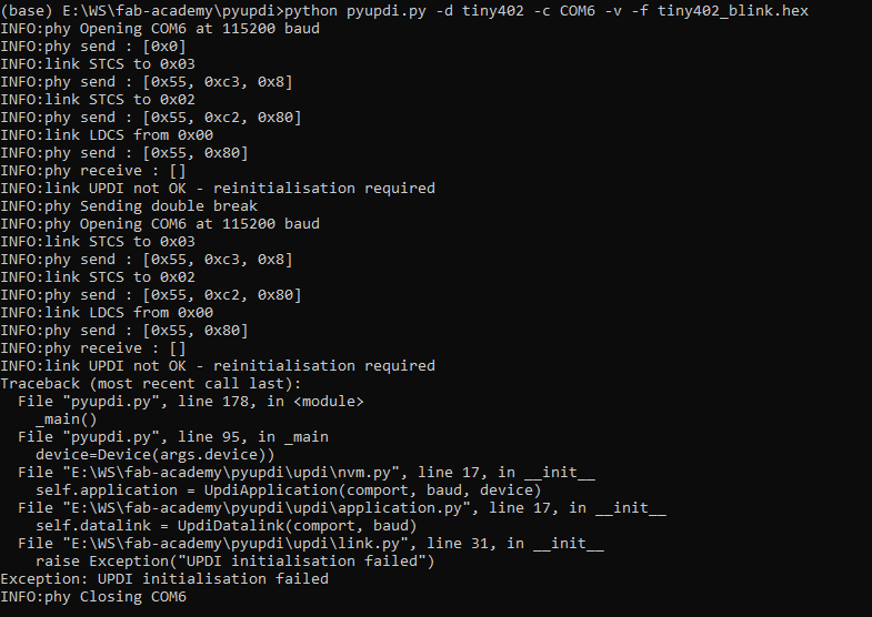
This step was pretty simple, but only because it wasn't on my initial test breakout board two weeks ago. More on that in the challenges section below. With those issues gone, programming through PyUPDI went off without a hitch! (except for having to lower the baudrate to limit errors... Which I'm willing to attribute to the terrible quality of the traces on my programmer board).
# Software
This part wasn't technically part of this week's assignment but you can't really expect a software engineer to look at a micro-controller and not want to write code for it...
So I ended writing a simple program to control the RGB LED on my board and make it cycle through colors in a rainbow like pattern. I also added the ability to control the brightness via the button on the board.
I eventually want to migrate to a more advanced toolchain like Atmel Studio and get rid of the Arduino environment but for this first attempt, I setted on the familiar. This turned out to present its own challenges: the Series-1 ATTiny family is not natively supported by the Arduino toolchain.
Thankfully, a great project called MegaTinyCore adds support for both the Series-0 and Series-1 ranges.
To implement my rainbow effect, I needed (or wanted, at least) the ability to convert from HSV color representation to RGB; this ended up being missing from the libraries available for the ATTiny, so I rolled my own implementation. This presented an interesting flash memory size challenge outlined later!
Here's the full final code for this really simple program.
# Results
And finally, the results of these efforts! The rainbow effect doesn't quite come through as well on video but it looks pretty decent in reality, and at maximum brightness this tiny LED is impressively bright (in an "ouch, my retinas" kind of way):
# Challenges encountered
# UPDI programmer
This step sounded like it would be simple, and in the end it was, but there were a few false starts two weeks ago with my first breakout board, seen here unpopulated:
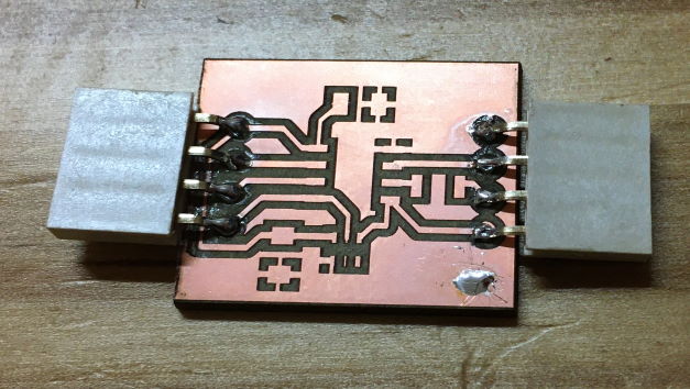
The programmer I had made was recognized as a USB to Serial device in Windows, was assigned a COM port, and all seemed well... Until I tried to actually upload a file. At that point, PyUPDI reported receiving no response from the target.
Without a logic analyzer on hand (and with very rusty skills in using an oscilloscope), the best I could do was confirm that something was indeed happening on the UPDI data line:
This was not particulary helpful, though. I wracked my brain for a one, tempted to blame:
- PyUPDI; it doesn't seem to be a heavily used project, maybe I was running into some bug
- Windows: maybe that bug was OS specific? I had a hard time finding examples of people using PyUPDI on Windows online
- a difference in logic level between my target (running at 5V) vs the programmer (apparently running at 3.3V)
After trying things a little too aimlessly, I realized that PyUPDI has a specific error output if it's not seeing an echo to its outputs: since UPDI is a one wire protocol, the TX (transmit) and RX (receive) lines of the UART are tied together, so anything sent out is immediately seen as received. PyUPDI validates that is is indeed happening, and was not throwing an error.
In a bit of a (very belated) eureka moment, I realized that, if the echo was correct, as doubly confirmed by a terminal app:

then that had to mean that my programmer was working... the target was just not receiving the commands, or not transmitting back.
I used this helpful guide to test programming my target with an Arduino Uno acting as UPDI programmer, and that worked. The difference between the two finally hit me: in following existing breakout board designs for the ATTiny412, I had added a resistor to the UPDI line (to limit current, I'm assuming), but this resistor was also present on my programmer! The combination of the two was enough to prevent communication.
I simply replaced the resistor on the breakout with a 0 Ohm resistor and everything started working! And of course removed that resistor from this week's breakout design entirely!
# ATTiny flash memory
It's great that ATTiny is supported in the Arduino IDE and that (some) libraries will work... but you may not want to use libraries. I had to do some rather ugly things to get my code down to the smallest possible size so that I could get the LED and button libraries I wanted to fit (because I was way too pressed for time to implement the WS2812B and clean button debouncing myself right now!)
After quite a lot of hacking, this is the final size of my program:

To give a little more details:
- many libraries are incompatible with ATTiny Series-0 and Series-1, even with MegaTinyCore; FastLED won't work, eliminating perhaps the best programmable RGB LED library out there
- MegaTinyCore comes with a cutdown version of the Adafruit_Neopixel, though!
- Libraries may be a bad idea with so little flash memory, anyway
- Both for flash consumption and performance, you'll want to watch out for floating point operations
- You'll want to be particularly careful with division, which is apparently not implemented in hardware in AVR!
- All in all, if possible, stick to integer math, ideally on 8 bit values
TIP
If you need to divide by a constant factor x... pre-calculate 1/x, put that in a constant and multiply by it!
# Exporting from CircuitMaker to PNG
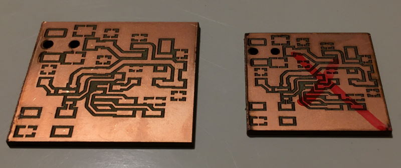
As mentioned above, I couldn't find a good way to do this, so I ended exporting Gerber files, opening them in Gerbv, and exporting PNGs from there. This works great, except that Gerbv appears to export based on the zoom level on screen... completely messing up the scaling. In the end, after a painful hour of trying every option I could think off in both CircuitMaker and Gerbv, I admitted defeat on this issue (for now!) and simply rescaled the PNG to the desired size in Illustrator before sending it to the laser cutter. It's ugly, but it worked and produced the correctly sized board on the left, instead of the first attempt on the right that was entirely too small!
# Missing components in CircuitMaker
This was bound to happen eventually: I switched to CircuitMaker in part because it's Cloud based community library makes it easier to find modern components without downloading random library files full of other crap from the internet like you have to do with some other ECAD applications (looking at you, Eagle!), but I eventually found a part CircuitMaker didn't know: the power jack I used to connect my battery.
Thankfully, this turned out to be pretty easy to solve by simpling following this tutorial in the CircuitMaker documentation on how to design your own component.
# Laser cutting PCBs
A couple of interesting problems croped up during laser engraving of the PCB:
- If you significantly lower the number of passes, the engraving will be much faster, and the design will look great on visual inspection... until you E-test your board! You'll then realize that there is still enough copper left in the engraved (and non copper looking) areas to make those areas conductive!
- Even with enough passes to actually remove copper, E-testing will sometimes find connections that should not exist between traces. If you break out your lab's USB microscope, you'll find things like these:
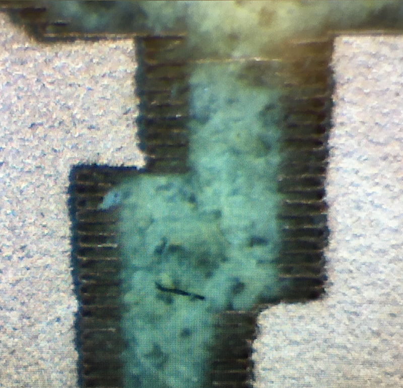
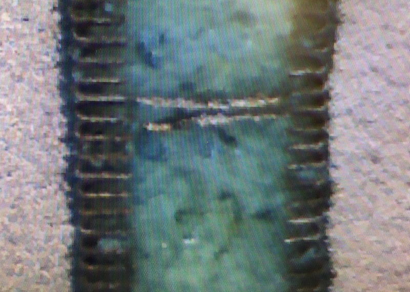
There are near invisible to the naked eye but apparently conduct enough to short out traces! I wonder if any significant current would burn them away, or if they would make your circuit fail... I decided not to tempt fate and cut them with a sharp blade. After that, the blank PCB tested as expected.
# Learning results
- Laser cutting PCB seems very promising! I would love to find time to experiment with double sided PCBs and via with this approach
- I've gained a little more experience with CircuitMaker and I'm happy with my choice to migrate from Eagle
- ATTiny can work with the Arduino IDE, which is nice, but there are some serious limitations that make me even more eager to abandon the Arduino toolchain in favor of a native AVR toolchain
# Things left to explore
- simulate the circuit (try Falstad online)
- debugging: my big hope with a UPDI programmer was to explore debugging, since the protocol is designed to unify programming and debugging over as single wire and the Series-0 and Series-1 ATTinys have a dedicated pin for this. Unfortunately, this turned out be be more complex than I had hoped. I had foolishly hoped that Atmel Studio might be up to this task even on code built with the Arduino toolchain (likely limited to stepping through assembly, but this would still have been interesting). Sadly, it seems like actual debugging requires hardware far beyond our simple programmers, either in the form of an actual development board, or at least a device like the Atmel-ICE. Need to investigate!