# Group assignment
This week's group assignment was to characterize the laser cutter in our particular lab, i.e. get reasonable values for speed, power, kerf, tolerances, etc.
We ran into two issues while trying to do this:
- the material database on our Trotec is (at the suggestion of a Trotec specialist who performed the last round of maintenance, and with my approval as a mentor for this particular machine in our lab) currently locked. The logic here is that most users should actually not change the speed and power settings; these are easy to get wrong and getting darker or lighter engraving should mostly be done through the (available) raster settings and the color or grayscale nature of the graphics to be engraved
- our current recommended process for our Trotec is to go through Illustrator but we had difficulty getting colors to go from Illustrator to the driver and ultimately JobControl unimpeded. We believe this is due to Illustrator automatic color correction (that attempts to match colors on screen with actual printable colors) but we were so far unsuccessful in getting anything beyond black and red to go through, making it harder to use colors to select speed and power profiles
The first issue was solved in agreement with the lab managers by distributing the materials database password to students.
The second issue still had us stumped as off Tuesday evening. While writing this up, I attempted to recreate a quick testing template from scratch with every possible option I could find in Illustrator set to raw RBG with no color correction. Testing of this approach is pending!

We did however manage to collect a few pieces of information regarding our laser cutter:
- on cardboard, my classmates measured the kerf at around 0.1mm; based on personal experience with making plywood designs, I would say this is reasonably accurate
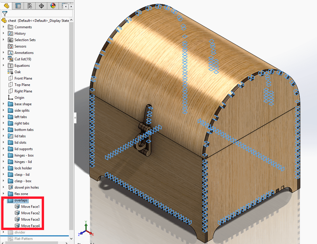
- again based on personal experience with plywood design, my preferred design approach for tolerances is to make the thickness of the plywood a parameter (T) in the CAD design and set it to the nominal value for the material; before cutting, the actual work piece can be measured with calipers and the CAD model can be updated. For ~3.2mm plywood, I have found that introduce a "Move Face" feature with a 0.2mm offset on tabs (or slots, but not both) - resulting in about 0.4mm of interference in the CAD design - results in extremely strong press fit joints that require significant (but reasonable) force to assemble and are unlikely to come apart.
Here's what those features look like in a CAD model:
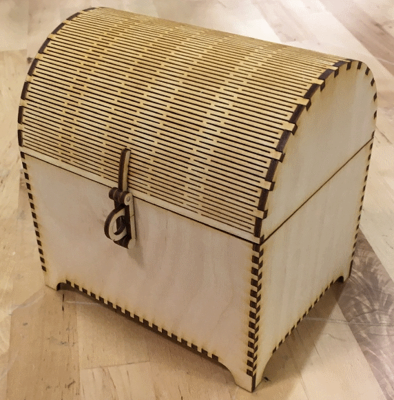
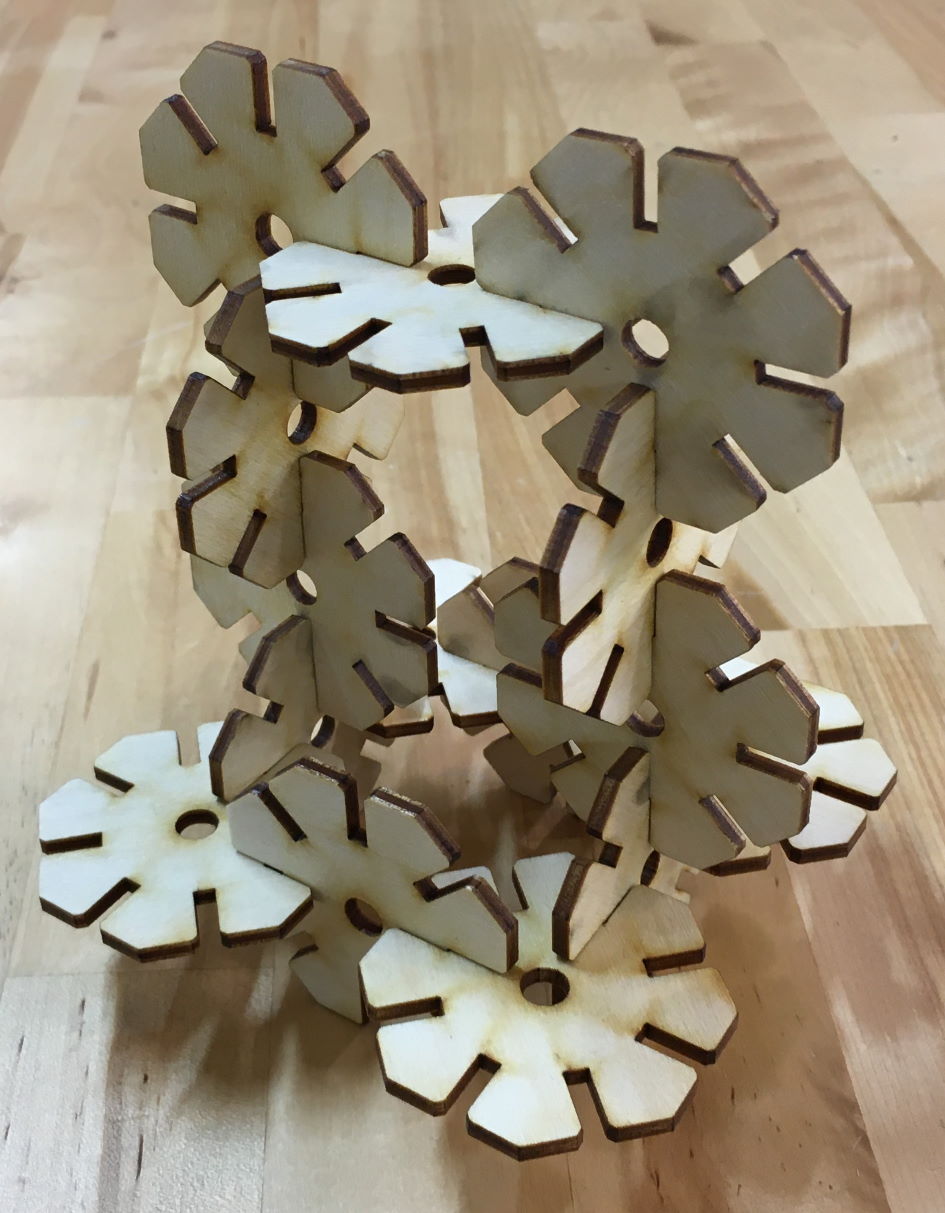
Here's an example of such a design: there is no glue anywhere in these joints:
# Construction kit
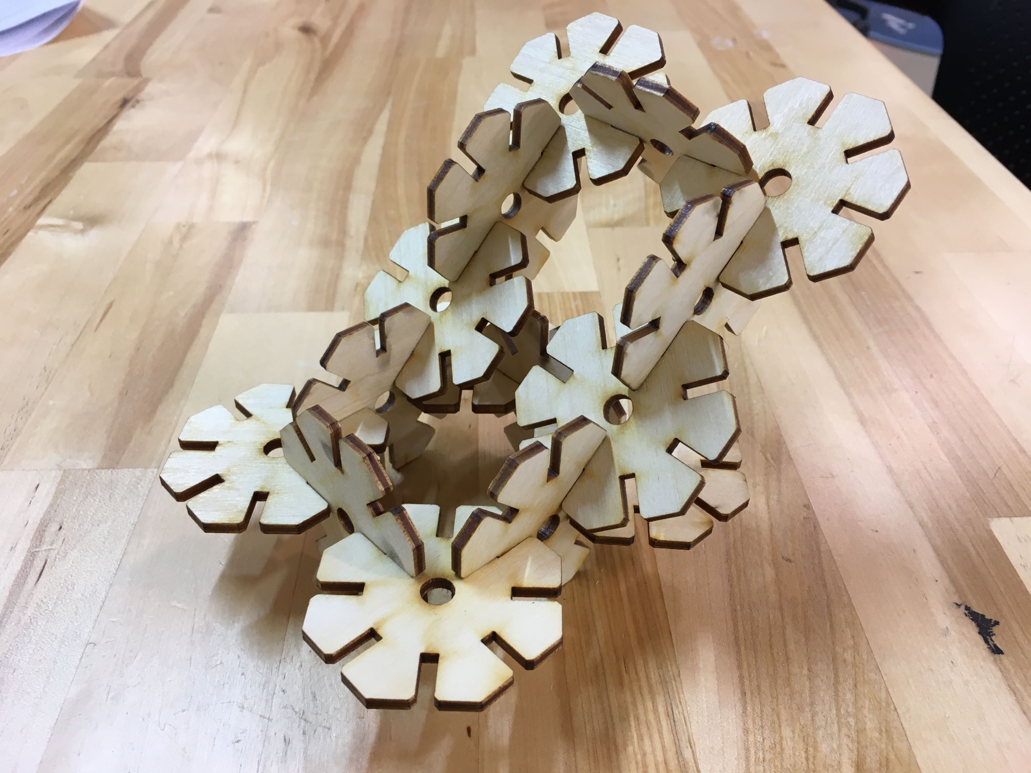
Last week, I modeled a simple octagonal base piece for a construction kit. I decided to simply laser cut this and start playing with it to figure out if it was any fun in practice.
Despite the really basic approach to a construction kit, it was actually really fun and easy to make... something:
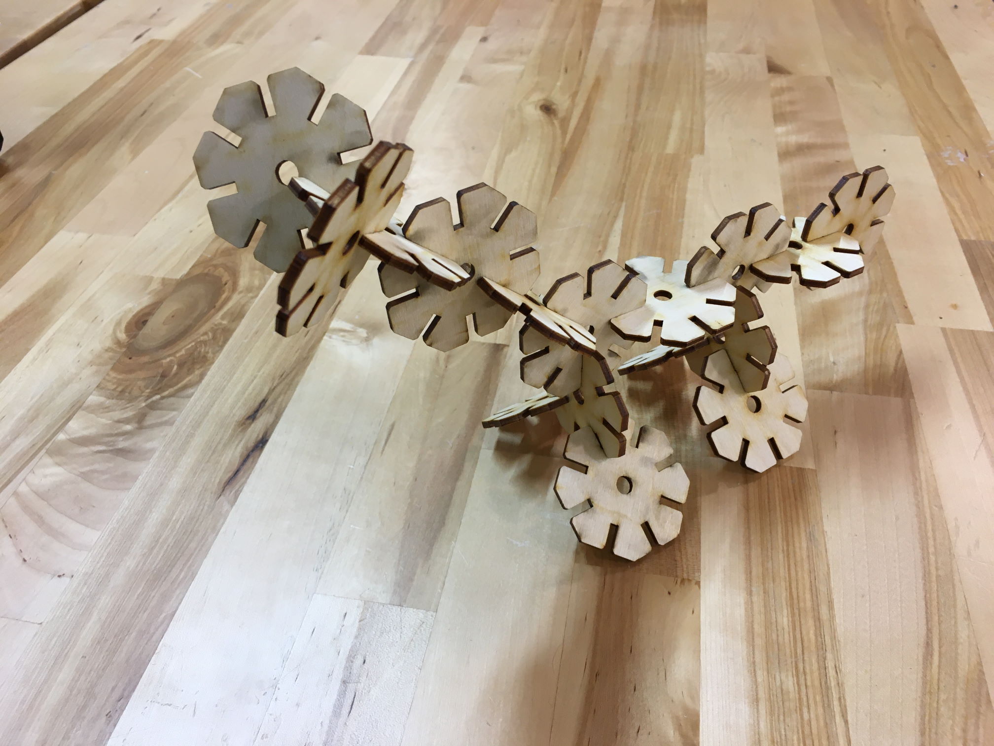
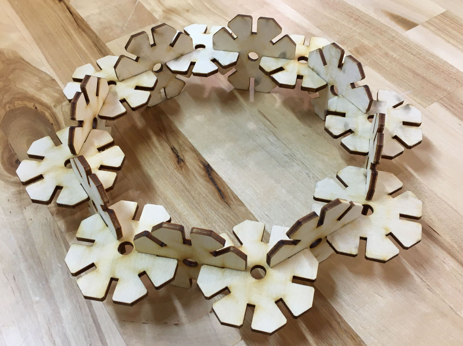
This inspired a second version of the construction kit with more pieces!
Back to the Trotec we go:
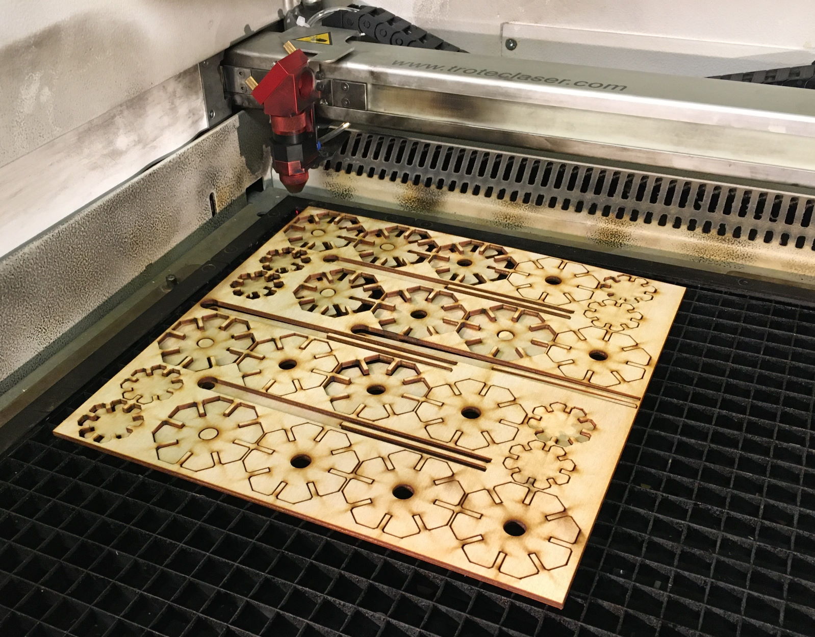
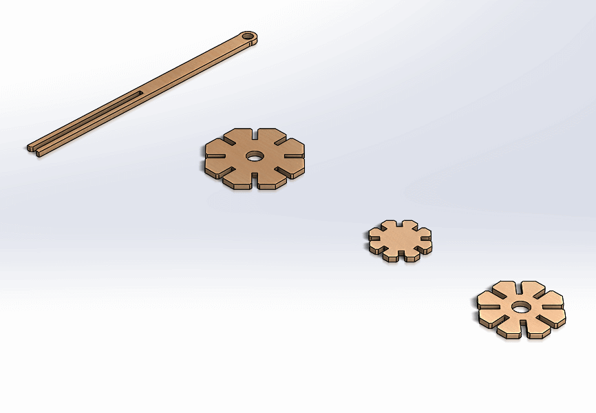
resulting in these designs:
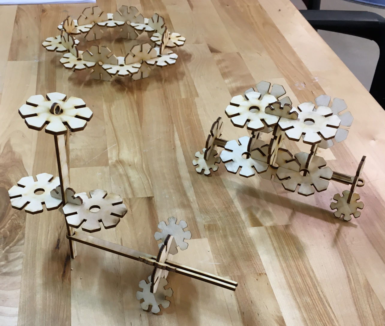
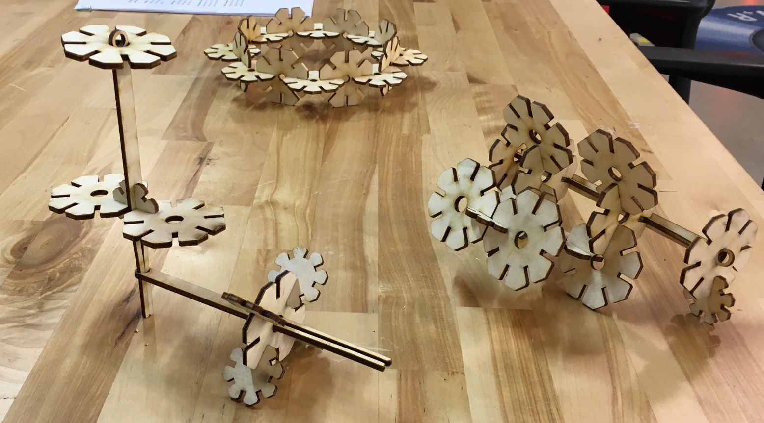
In an attempt to formalize this design a little, I added one last shape to the set and decided to name them:
- large flower
- small flower
- snowflake
- tuning fork
These are all really simple in CAD (though they are all parametric so they can be quickly adapted to the material thickness and scaled up or down while retaining their relative sizes for assembly) but they are entertaining to play with!
As of this writing (Tuesday evening), time constraints have prevented me from cutting the latest version with the smaller flower, which I hope will allow for designs with "wheels" (made up of the large flowers) supporting a structure. Stay tuned for an attempt to cut and assemble these new shapes soon!