15&17. Machine design
Our assignment for this week was a group project to design a machine that includes mechanism+actuation+ automation, build the mechanical parts and operate it manually, and document the group project and your individual contribution
Brainstorming
We began by looking at past projects that people made for this week. Some ideas we were interested in including:
- a time-lapse dolly
- a fab inventory management system
- a “lunch generator
- a pantograph
- a pancake maker
Coming Up With the Idea
We all got on a group call and went through some new ideas together. We searched through students’ sites from previous years, and eventually found this pancake maker machine that we all really liked.
We did not want to copy their whole idea, so we tried to think of other foods that would work. Almost immediately, cupcakes came to my mind. The machine we would make would fill a cupcake pan with the correct amount of cupcake batter. After pitching the idea to the group, everyone liked it, and so, our cupcake machine was thought up. Now, we just needed to actually make it. For the full documentation of this project, check out our group site. Down below is a a collection of initial notes we had along with my own personal contribution to the machine which is marked.
Materials
| Item | Measurement |
|---|---|
| Elaine’s Cupcake pan | 15.25”x10.8125” (width x length) |
| Cupcake hole diameter | 2.875” |
| Distance between two holes | 0.46875” |
| Distance between the centers of two holes | 3.34375” |
| Volume for individual cupcake hole | 95 mL |
| Pulley and belting | - |
| Linear rail | 12mm |
| Driver shield/ stepper motors (grbl boards) | - |
| Batter dispenser | - |
Initial Idea
We would have a bag with the mix and a mechanism to “release” the cupcake batter from the bag. This way, we would not have to worry about the batter becoming stuck in motor, as we thought we would have to if we used an actual dispenser. We would implement two-axis movement machine that goes over the cupcake tray following G-Code commands. We decided to use a different project that we had been considering as the inspiration for the two-axis movement component - The pancake maker used the same two-axis movement component, but this project displayed it better.
Making the 2-axis movement
What we knew we needed:
- CoreXY
- PCB + microcontroller
- A motor of somesort ~ stepper or servo
- Steel pipes
- Belt + pulleys: 6mm wide belt + pulleys
- End supports: to be laser cut with acrylic + 3D printed components
We looked at Barcelona’s design for inspo on the mechanics of the pully and motors.
Stepper motors/code (Sophia and I):
Info about the motor:
- Steps per mm for our stepper motors: we have to figure what parts were using then find this in the datasheet
- The calculator for calculating the microsteps
- Datasheet for the motors we are using: Go to the line under 4401
- Another datasheet
- Rated current: 1.7 amps
- Torque 40 units of whatever
- 2.6Vdc
- Powering the motor
- Arduino Tutorial on Stepper Motors
We learned that the gantry was the axis that sits on parallel axes. We then looked on amazon for pulleys and belting. For the batter dispenser idea, we researched more about grbl and using gcode through it. We needed to gauge if we would have enough control over the dispenser and if this route would be the most efficient. Through our research, we found that GRBL was an open source cnc control software.
Materials for the Release Mechanism
The batter is going to be stored in a dispenser which works by pulling the handle in order to release the batter. Therefore, we needed to create a mechanism that would be able to push or pull the handle so that the batter could be dropped into the molds. The idea that we came up with was that there would be a curved 3D print that would be attached to a servo motor which would push the lever over so that the dispenser would release the batter. After sketching out the idea, it was time to model the 3D part. We went on Fusion 360 and made a simple design that would attach to the servo motor and push the lever over.
Partnered + Individual Contribution
Because there are 7 members in our group, we decided it would be best to split into smaller groups to work on a singular aspect of the machine. I partnered with Sophia to work on the electronics and coding aspect of the machine.
Research:
We referenced this site to find out what materials we might need.
Sophia’s notes:
-
Steps per mm for our stepper motors: we have to figure what parts were using then find this in the datasheet
First and foremost, we laid out what we might need for the stepper motors, what connections we needed, etc.
- Stepper motors
- Stepper motor drivers
- Pcb’s
- Arduino shield board, datasheet, Using attiny85 as driver
Motors - Sophia
We decided to use stepper motors for the gantry mechanism, and but also for the batter release mechanism. We chose to use stepper motors, and started looking into how to use them.
We bought this kit which included the shields, the drivers, the motors, and even an arduino.
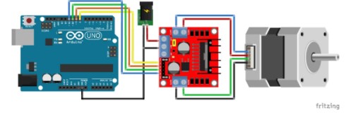
Shield/Drivers - we are using a driver module specific for arduinos. The motor we are using was made specifically with the intention of interfacing it with an arduino. The drivers/shields setup we are using will allow us to control the motor’s speed and direction with the arduinos while also regulating voltage between the low power consuming (about 5 volt) arduino, and the high-power consuming batteries.
Our power supply will be a wall adapter. This type of motor was made to use either this type of power supply or a lead-acid battery according to the datasheet
We needed to figure how to set up the shield to power the stepper motors. Adafruit contained very useful information about the type of batteries that we would need and also warned us against connecting the motor’s power supply to the arduino’s power supply. Many of the sites listed in the Gantry section were also helpful for coming up with this wiring setup:
Wiring for the motor:
GRBL (both)
GRBL is a free, open source, high performance software for controlling the motion of machines that move, that make things, or that make things move, and will run on a straight Arduino. The language it reads is G-code, which is the list of instructions often used for automated machines (i.e. CNC machines, milling machines, 3d printers…) to instruct the machines on what tools to move/how to move them, in order to make something.
GRBL protocol will be uploaded to arduino and will communicate with G-code that we send to the arduino.
First we had to familiarize ourselves with GRBL. We looked at these sites to learn how to install GRBL and also learn some basics as well.
How to install GRBL: site
We downloaded the GRBL.zip files and added them to Arduino as a library.
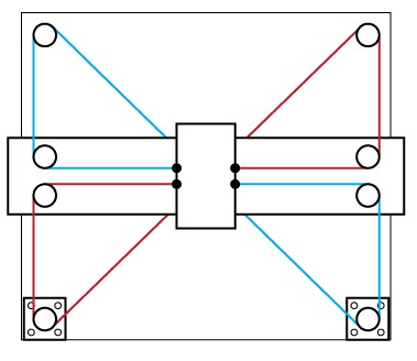
We then worked on making sure it would be compatible with our specific device. After looking at the config.h page on the github grbl page, we realized our gantry and the software were not compatible. During the first part of this project, we designed a gantry system with the rest of our peers that was not a COREXY system. However, GRBL is compatible with COREXY gantry machines only.
We reached out to Alex and Elaine, our classmates who were responsible for the CAD model of the gantry, and found out that we were, fortunately, able to tweak the design so it matched the COREXY gantry design seen below.
Creating the G-code - (me)
There are a couple of different ways to write G-code. There are different dialects which make it so that each code is relative to the type of machine it runs on.
After a discussion with our teacher, he told us that it would be best and very possible to write our own g-code from scratch which would probably have around only 50 lines. I wanted to create a rough draft of the code, leaving out the details, just to have an outline that we could fill in and edit later. Because I am relatively unfamiliar with the language, I took some time to read through some info about the language. First and foremost, I needed to know how to start the code. This write up from Autodesk was very informative on getting started and the necessary basics of Gcode. I learned that g-code stands for “geometric code,” and follows some variation of the alpha numeric pattern: N## (line number) G## (Motion) X## (Horizontal Position) Y## (Vertical Position) Z## (Depth) F## (Feed Rate) S## (Spindle Speed) T## (Tool Selection) M## (Misc functions) There’s also I and J which are the incremental center of an arc and R which is the radius of an arc. G defines the motion and function, XYZ declare the position, F and/or S set a value, T selects an item, and M switches things on and off (ex: coolant, spindle, etc.)
According to Autodesk, g-code tells the machine to do one of these three basic motions and how to do it: Rapid move: a linear move to an XYZ position as fast as possible Feed move: a linear move to an XYZ position at a defined feed rate Circular move: a circular move at a defined feed rate
I just wanted to get started with messing around with g-code, so I used the website-based program, Chilipeppr to do some hands on learning.
First, I had to set up the serial port JSON server. This honestly took me a bit to figure out because in the video that I was using, the site sent them directly to the set up of the port whereas now, it sends you to JSFiddle. I simply ran the code, and the same screen as in the video showed up in JSFiddle.
Setting up the Motors (both)
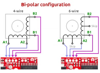
We had one more motor that we needed to configure for our machine. At first we wanted this to be a servo because we believed that it would be the most effective in controlling the release mechanism for the batter. However, after speaking with Dr. Harris, he recommended that we use smaller unipolar stepper motor, specifically the step motor 28BYJ-48, for the spindle release mechanism. Because this stepper motor is unipolar, and our shield only has four pins which account for bipolar motors, we needed to kind of “hack” the motor to be bipolar.
We found this YouTube video which explains how to do this. This website gave us a diagram of the colors and coil numbers and also provided the datasheet for the stepper motor.
How to change unipolar to bipolar:
For the gantry, we needed two X-axis motors and one Y-axis motor. We needed a driver for each so that we could have a stable amount of control on where they went for all of them. We connected the two x motors to be in sync with each other by shorting the blue and yellow pins on the side with jumper wires. The z-axis motor ( our “spindle” - actually the release mechanism) was connected to a separate set of pins and had its own driver.
Testing and Issues (both)
Once we had GRBL uploaded onto Arduino, we opened up the serial monitor and started typing in basic commands like “g0x100” to get the x-axis motors to move. We tried to clone the two x-axis motors by “connecting” the blue pins to the yellow pins as we learned in this video. There are alternate X axis Pins on the shield that will clone the x axis movement.
We had connected the jumper wires from the blue to the yellow twice instead of shorthanding them. This was a mistake on our part because the man in the video clearly stated what to do.
This caused the original motor - not the clone - to run way faster than it was supposed to.
Once we figured out what to do, we fixed it and they worked!
Group Page
Here is our group page with the completed work!
Takeaways
Overall, our machine was successful. There are many ways we could take this such as directing it to draw shapes perhaps or controlling the amount of batter that comes out at certain times. We could add a touch screen that controls all of this for easy accessibility. Who knows? I really liked what we built!