11. Input devices
The individual project this week was to measure something by adding a sensor to a microcontroller a board that we have designed and read it. For the group project, we were required to probe an input device’s analog levels and digital signals.
With our FabLab closed due to the coronavirus, I was worried about how this week was going to play out; however, with the help of my fab teachers and fellow classmates, I was able to do as much as I could from home.
EAGLE // Fail
I’ve come to accept the fact that I am just not good at maneuvering through EAGLE, yet. During the Electronic Production week, I struggled immensely with designing my board which I came to conclude was from a combination of hopping around computers too much and also not knowing Eagle. I have gotten better as I have used the program more, but, obviously, I am still very rusty.
At first, I chose to use an A1324LLHLT-T as my input this week to measure magnetic field, but I switched to a photoresistor because we had those on hand at the lab whereas we would have had to order the sensor.
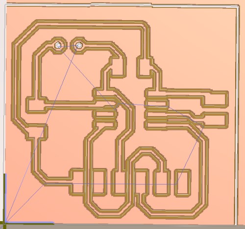
Designing my schematic was the easy part. There were very little issues, and if any occured it was something like me forgetting how to use the tools. The board file was the hard part. I ran into the same issue that I did during week 7, which was that the pads of my components on my board were not showing up in Bantam. Last time, I fixed the issue by switching the part multiple times, but honestly, this time, I did not have the patience for that nor did I think it was a problem with the parts. It had to be something that I was doing.
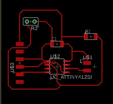
I consulted this issue with Mr. Rudolph, but he could not find any issues with my file in terms of why the pad was not working. I did forget a ground connection, so I fixed that, but once that was done, the pads were not showing up.
After a bit of trying to open the file in Bantam and EAGLE on his computer and mine, he told me that it was probably an EAGLE issue and to uninstall then reinstall the program. This fixed the issue. After, I made a new file, made my schematic, then routed the components on the board, and opened it in Bantam. Everything worked fine, so I think the issue was with how I originally installed EAGLE.
Soldering // Fail
I’m not going to lie - this took way longer than it needed too.
Because were are practicing social distancing right now due to the coronavirus, my teachers are creating bags with the parts and boards that we need and leaving them by the door of our lab. After picking up my parts and my milled board, I quickly got to soldering.
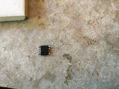
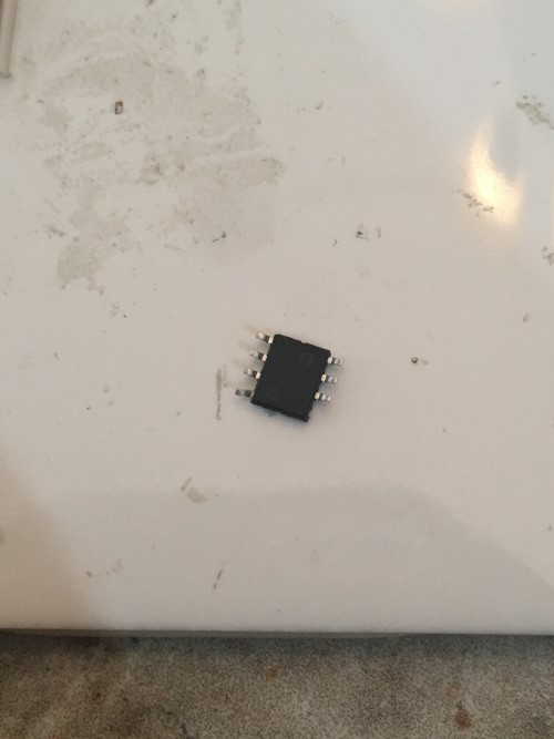
The first thing I normally solder is the microchip, so I went for that first. However, there was a pin missing from the chip. Luckily, my teacher packed me another one, so I was good to go.
I finished my board within 30 minutes and was extremely happy with how it came out. I did rip half of the circular through hole trace, but I did not think that that would be a problem as long as there was a somesort of connection between the photoresistor and the trace.

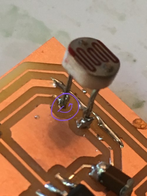
I was wiring the board when I absentmindedly picked it up by the two-prong pins, and ripped their trace. I was in extreme shock, but I kept calm and decided to solder a new board. I do not have a practically unlimited amount of components like I would normally at the lab, so I decided to use the components from the failed board. In taking off the parts, I broke a pin on the microchip and almost ruined the photoresistor. I would like to thank my teachers for being extremely considerate because although I only asked for one microchip, they gave me three. They also gave me another photoresistor, so I used that as well.
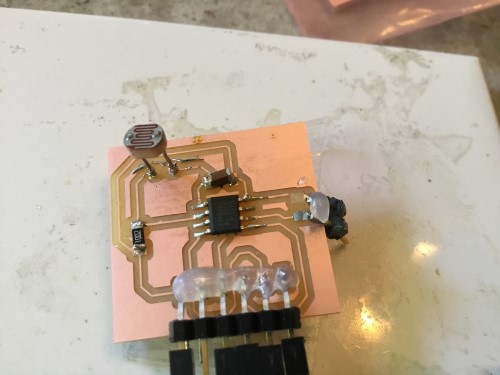
This time I was extremely careful, even more so than before, and the board came out well. I used a hot glue to secure the prongs down even more.
Wiring and Coding // Fail
As I mentioned earlier, I used a photoresistor as my sensor. My first question was what is a photoresistor? After a quick Google search, I found that photoresistors are light sensitive resistors whose resistance decreases as the intensity of light they are exposed to increases (c:ResistorGuide)
I thought it could be interesting if in my final project, I could have the LEDs dim when indoors and brighten outside. Although my final project plan has changed, I think in future projects I would like to implement photoresistors somehwere.
For this week, I wanted to read the light value of a room through the serial monitor. I am thinking that it could return a 0 if it’s dark and maybe a 1 if it’s light? I do not know yet.
I tried out both of these codes:
#include <RBD_LightSensor.h>

RBD::LightSensor light_sensor(A0);

void setup() {
  Serial.begin(115200);
}

void loop() {
  Serial.println(light_sensor.getPercentValue());
}
and
#define lightSensor A0

void setup(){
  Serial.begin(115200);
}

void loop(){
  int lightLevel = analogRead(lightSensor);
  Serial.println(lightLevel);
  delay(1000);
}
when I realized something very vital. I think my board was completely wrong. I had no place to connect to the analog pins on the arduino and connect the sensor to the serial port. I also realized that I should have added an LED to my board, so that for testing purposes. Sadly, I think I may have to make another board.
Following this website’s instructions, I created a set up that I thought would work. It did not. It gave me the same error as the last 100 tries.
However, to top it all off, I though I burnt out the microchip. It was getting hot when I plugged it in earlier, so I let it be for a bit, but now, it is not even heating up. I checked with a multimeter, and everything was good, so that was a relief.
Restarting
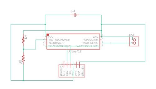
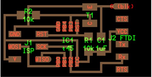
Like a lot of other weeks, I took a step back from this week for a while. After about two days, I decided to restart and make a whole new board. Instead of using a photoresistor, I used a phototransistor. Using the board Niel made as a reference, I made my own board except I switched the Attiny45 for the 412.
Here is his board:
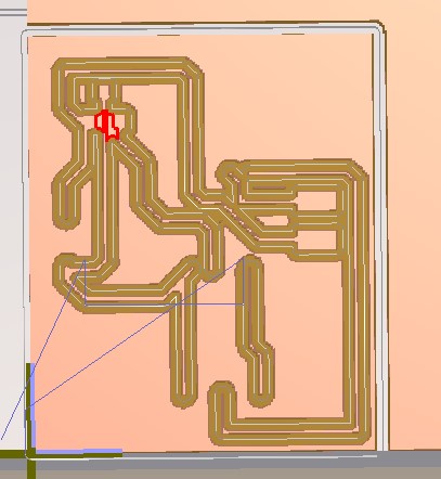
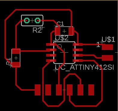
Here is mine:
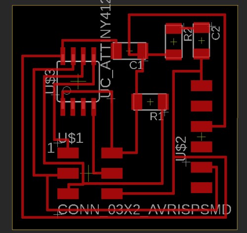
Milling + Soldering
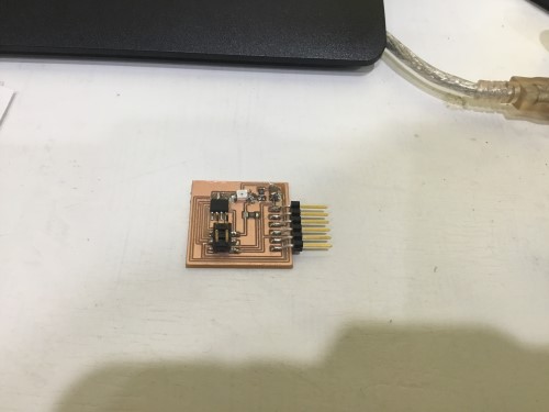
I’ve improved in making boards and milling tremendously. It only took me about 30 minutes in total to create my schematic, route my board, and mill it out which is a big big improvement for me.
After milling the board, I got straight into soldering. At first, I could not get the solder to stick to the board and as a result, the first components that I soldered on were very messy. I asked Elaine for help and advised that I keep the soldering tip on the copper pad until it gets hot enough to melt the solder. Then, add the component afterwards. This helped me exponentially. The difference between the components I soldered before she helped me and afterwards is very visible, haha.
Wiring + Programming
This is an extremely weak spot for me as I have little experience with programming and electronics, but this week I have learned a lot. I made sure I had the pinout of the attiny412 visible at all times to make sure that I was wiring to the arduino correctly from my board.
I looked online for some codes that I could test and use as a reference and found these:
#include <SoftwareSerial.h>
SoftwareSerial mySerial(0,2); //rx,tx

byte sensorPin = 3;

void setup() {
  mySerial.begin(9600);
  pinMode(sensorPin, INPUT);
  }

void loop() {
int buttonstate= analogRead(sensorPin);
mySerial.println(buttonstate);

}
While the one above successfully uploaded, nothing happened. I’m not sure why, but I did not look too deep into it and moved on due to the time constraint that I had.
#include <SoftwareSerial.h>
SoftwareSerial mySerial(0,2); //rx,tx

byte sensorPin = 3;

void setup() {
  mySerial.begin(9600);
  pinMode(sensorPin, INPUT);
  }

void loop() {
int buttonstate= analogRead(sensorPin);
mySerial.println(buttonstate);

}
This one did not really work, but it kind of did? It was extremely weird. At first, I did not have a wire connecting the TX pin to Digital pin 2 on Arduino, so after I added that it successfully uploaded, but yet again - did nothing in the serial port. I looked up what ‘buttonstate’ meant, but my search was unsuccessful. Again, I decided to drop it and continue my search for a different code.
Finally, I found this code that finally worked. It measured the phototransistor’s voltage when different levels of light were flashed onto it.
/*
 * Robotics with the BOE Shield - PhototransistorVoltage
 * Display voltage of phototransistor circuit output connected to A3 in
 * the serial monitor.
 */

void setup()                                 // Built-in initialization block
{
  Serial.begin(9600);                        // Set data rate to 9600 bps
}

void loop()                                  // Main loop auto-repeats
{
  Serial.print("A3 = ");                     // Display "A3 = "
  Serial.print(volts(A3));                    // Display measured A3 volts
  Serial.println(" volts");                  // Display " volts" & newline
  delay(1000);                               // Delay for 1 second
}

float volts(int adPin)                       // Measures volts at adPin
{                                            // Returns floating point voltage
 return float(analogRead(adPin)) * 5.0 / 1024.0;
}
Here is a video of my board working:
I tested it with other baud rates and changed the A3 pin to A2, changing the wiring as well, and this is what happened:
In order to make more changes to the code, I changed it from saying “__volts” to “__sydney”.
Here is a video of that:
My files:
Takeaway
Although this week was frustrating and confusing at times, I feel like I learned some core lessons like a deeper understanding of how microchips work and what a UPDI is used for. I think that going forward, I will pay more attention to the little details and not rush as much.