12. Output devices
This week our individual assignment was to add an output device to a microcontroller board we’ve designed and program it to do something. For the group assignment, we had to measure the power consumption of an output device.
Designing
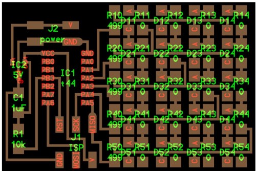
Because my whole final project is based around LED arrays, I chose to do Charlieplexing for this week. This website provided by Niel discussed how to “Charlieplex” a display driver circuit to reduce pin-count. I started by looking at Niel’s board, and tried to find what components I would need. My teachers graciously have an order spreadsheet for us to ask for parts that we need. Mr. Dubick, one of my teachers, makes bags for us that we can pick up at school without having to actually go inside the lab because of the pandemic.
I noticed that Niel had a part that I was unfamiliar with on his board. I looked on eagle and found that it was a 5V voltage regulator. Not knowing what that was, this website provided a very useful explanation of the component. However, Niel used an SMD voltage regulator, and after searching my lab’s electronics storage spreadsheet, I saw that we only had a through hole 7805 IC 5V voltage regulator. I opted to use this and simply make sure that I designed my board as such.
In this week’s video, Niel explained that only a certain number of pins were necessary when charlieplexing because of the way it is set up. After watching his explanation of the technique a couple of times, I stilled needed a little more clarification, so I read through this Instructables page this YouTube video.
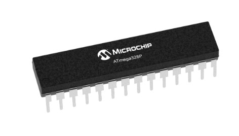
I decided to use an atmega328p. I could not find it in any of my pre existing eagle libraries, but from this forum, I learned that I could use the library for Arduino’s Mega168 or Mega88. I found the in the atmel library, the Mega8-P would be compatible.
Looking at the pictures however, I realized that I was looking at the entire wrong piece. The microcontroller I was looking for was square, not rectangle, and SMD not through hole.
This website was very helpful in explaining how to use the atmega328 for charlieplexing. I looked at the datasheet for the component, and tried to find something that had the same pinout in the libraries in eagle. I was not successful. I ended up using the Mega8-P which had the same pinout as the Atmega328p.
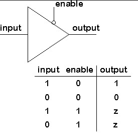
After doing this, I still did not understand charlieplexing. I don’t know what was not clicking, but it just wasn’t. By this time, it was the end of this week, but I was no where near being done. I had all my components, a pretty poor schematic, and no board. My instructor, Dr. Faegan, recommended that I speak to Will Knight, a Fab Academy alumni, because he had done the same thing for his output week. Right off the bat, he introduced me to something called ‘tri-state logic’.
Essentially, he said that tri-state logic involves 3 different possible states and that it allows multiple circuits to share the same outputs with each other. This lets the output have a high impedance state which is a point in a circuit (a node) allows a relatively small amount of current through, per unit of applied voltage at that point (cr. wiki).
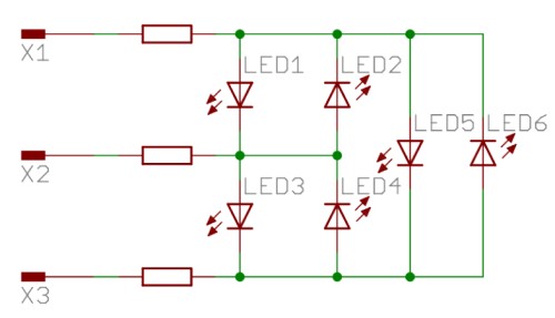
He also explained that the current will follow the path of least resistance. If there is a shorter/easier route to follow, that is where the current will go. For example, if there were four LEDs ligned up, the current would only pass through 1 led out of 4 bc it’s the shortest path. This is also due to the fact that LEDs only let electricity flow through one path. To understand how charlieplexing was layed out, he showed me this basic example with three pins.
For the programming part, he advised me to make sure the pin isn’t sending anything out nor can it recieve anything by setting the Output to low. This will ensure that it’s not sending any info that it’s not ready to send, and it will mess with other circuits.
After creating my schematic, I embarked on the long, long, long journey of making my board. It took me about two hours to make, but here is what I came up with.
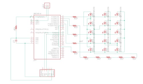
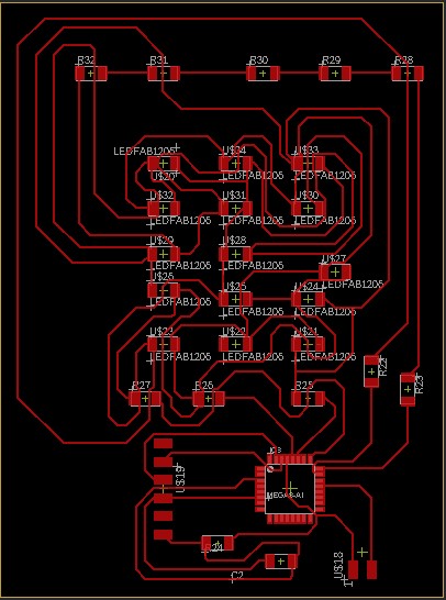
My files (bad): here
Soldering then Starting Over
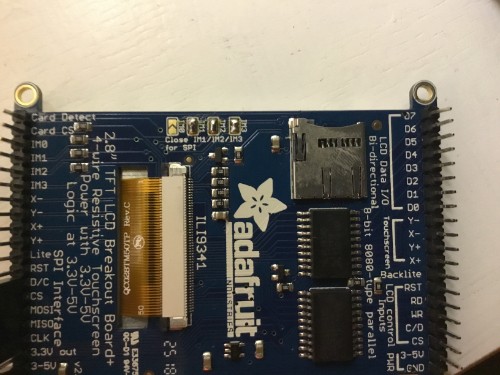
I soldered the ATmega328-P, resistors, capacitors, and one LED first. I tested the traces with a multimeter and it turned out that it was completely wrong. I had had enough, so I made the abrupt decision to change my output device. I still wanted to make this week relevant to my final project, so I chose to do a TFT display board. I am no longer using LEDs, but instead a TFT LCD in my final project.
I looked at Niel’s board for the TFT:
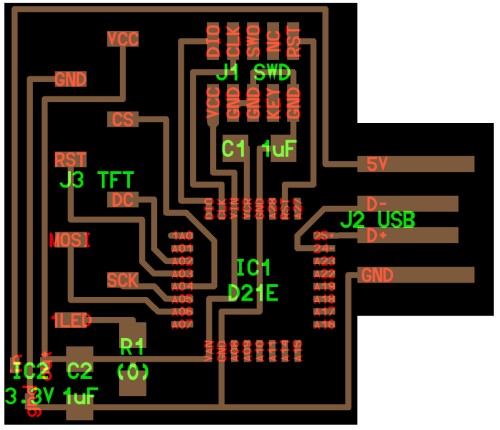
and used it as a reference. I am using a different LCD than him and also moved the capacitor and resistor around for my board. I looked at the connections he made and researched why he made each connection by viewing the video with the code he used. I saw that he just used something called ‘graphicstest.’ I have been working on my final project and have had to use the ‘graphicstest’ example (in the Adafruit TFT LCD library) for my LCD a lot, so I thought that this would be the perfect opportunity to make a board that I could plug my LCD into and load graphicstest immediately onto it without having to attach a bunch of wires to an Arduino and then back to the LCD.
I first started out by taking a look at the graphicstest example for my display. The code will be included in the zip file with all of my other files at the end of this week. I read through the pins which I kind of already generally knew due to how frequently I have been viewing this code.
// The control pins for the LCD can be assigned to any digital or
// analog pins...but we'll use the analog pins as this allows us to
// double up the pins with the touch screen (see the TFT paint example).
#define LCD_CS A3 // Chip Select goes to Analog 3
#define LCD_CD A2 // Command/Data goes to Analog 2
#define LCD_WR A1 // LCD Write goes to Analog 1
#define LCD_RD A0 // LCD Read goes to Analog 0

#define LCD_RESET A4 // Can alternately just connect to Arduino's reset pin

// When using the BREAKOUT BOARD only, use these 8 data lines to the LCD:
// For the Arduino Uno, Duemilanove, Diecimila, etc.:
//   D0 connects to digital pin 8  (Notice these are
//   D1 connects to digital pin 9   NOT in order!)
//   D2 connects to digital pin 2
//   D3 connects to digital pin 3
//   D4 connects to digital pin 4
//   D5 connects to digital pin 5
//   D6 connects to digital pin 6
//   D7 connects to digital pin 7
// For the Arduino Mega, use digital pins 22 through 29
// (on the 2-row header at the end of the board).
Niel made his 8 traces for his display by simply looking at his LCD, seeing what they needed to be connected to, and making those connections to the ATmega328P. I decided to do the same thing. This was the first time I strayed away from Niel’s example by not using the same core components as him. While I was a bit hesitant/nervous to do this, I was excited to push myself.
Eagle and Research
Opening up Eagle, I created a new schematic inside my “output week” project and began my heavy search for a 20 pin header. I eventually found a library called “pinhead-2” (also in zip file) and it had a bunch of pin headers. I made an agreement with myself that if I did not find a 20 pin header in this library, I would just use the four prong one or something and repeat it beside itself 5 times. Luckily for me though, this library came in clutch and had a 1x20 SMD header (big thank you to whoever wrote this library!).
Next, I had to get the microchip. While I could just use the Mega 8, I wanted to find a library with an actual ATmega 328P in it just to be sure that my connections were correct. I did this as a self-check, more than anything. I found a 328 in a libary called “IC_Embedded” by Fusion (also will be included in the zip....basically, just assume every file I mention will be in the zip).
I had used this this pinout-
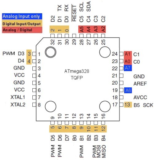
to make the proper connections for my failed part of this week, and the image has a “TQFP” under “ATmega328”. I took this as a green light and began making the connections as stated in ‘graphicstest’.
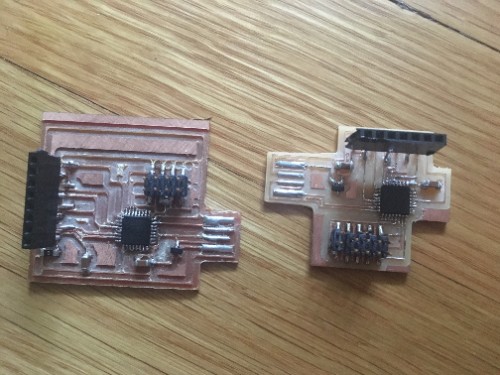
On his board, Niel also had 2x5 connectors, two capacitors, a jumper resistor, and a voltage regulator. Because I have never messed with these while making boards, I needed to do some necessary research about where to put what and if I even needed some of the components that he used - like the jumper, voltage regular, and the connector pins. From his video, I couldn’t see what the connector pins were for. Those were what I was the most confused about because my TFT did not have did not have a place for them at the back, but I couldn’t tell if his did. I then tried to figure out what they could be used for by looking at his board without the components (picture already shown above). I still had no idea what they were for. So, I dropped it and moved on!
I now needed to know when and where to add capacitors and/or a voltage resistor. I first went onto this article by adafruit to learn some more about capacitors and what they’re used for.
They said that “capacitors are widely used in electronic circuits for blocking direct current while allowing alternating current to pass.” With this information in mind, I began to understand that capacitors were necessary for directing current - kind of like a traffic light at an intersection. Still, I had no confidence in myself to place these in the right place, so I decided to go onto TinkerCircuits to test out different variations of potential designs. However, before I did that I needed to research voltage regulators (a pretty self-explanatory name).
According to Britannica.com, a voltage regulator is “any electrical or electronic device that maintains the voltage of a power source within acceptable limits. The voltage regulator is needed to keep voltages within the prescribed range that can be tolerated by the electrical equipment using that voltage.” With this newfound knowledge, I concluded that the capacitors and voltage regulator that Niel added to his board were to ensure that there was not too much current and voltage going to the TFT. They make sure that there is the right amount of current and voltage going to this display.
Before going to TinkerCircuit, I realized that I never trult learned about the difference between voltage and current. I knew that they were two different things, but I honestly had no idea what differentiated them nor what they were in general, to be honest. A quick Google search brought me to this super helpful website which explained what they were, their function, their relationship, and much more. I learned that they have a “cause and effect relationship”. Voltage is the cause and current is the effect. Current is unable to flow without voltage whereas voltage can exist withought current.
TinkerCircuits was utterly unsuccessful because I realized that they didn’t have the type of display that I was looking for. They had a basic 16x2 LCD, but I reasoned that I would be more successful just starting to create my board.
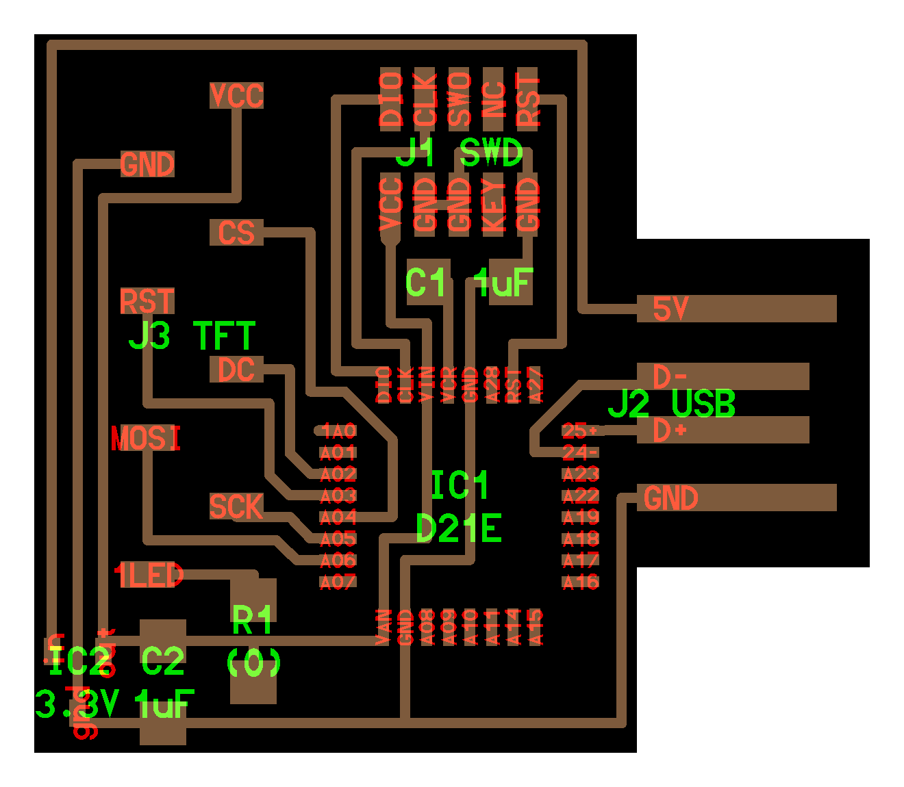
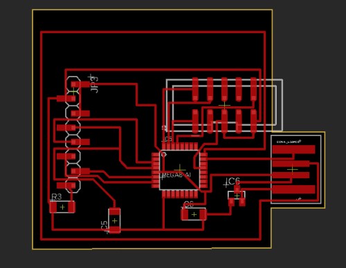
Looking on the page for my display, I found that for the SPI mode, I only needed about 8 pins, which was exactly like Niel’s example board. I took this as a clear sign and kind of just went with it because I did not have that much more time left in this week. Instead of doing the 20 pins like I had originally planned, I switched over to doing just 8. I switched around a couple of the traces to the capacitors to use less copper. Once I had completed those changes, I had my board. I ended up making two (explanation under “Electronics Production”)
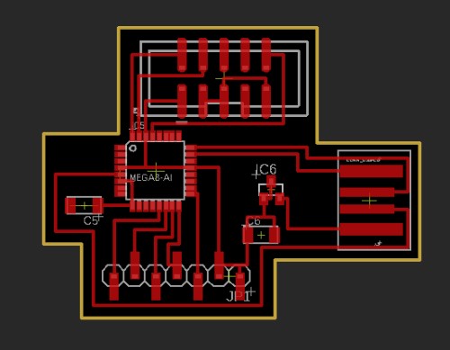
Here are the boards:
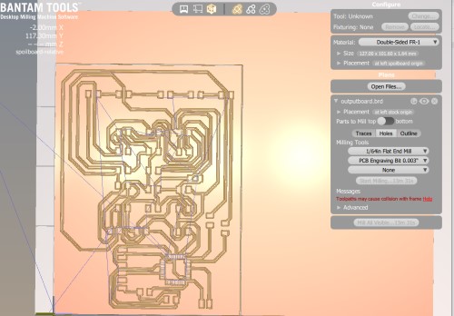
Electronics Production
I ended up making two boards because one’s USB port did not fit my dongle. At first, I had tried shaving off the ends of the board so that the USB would fit, but it ended up being useless. Here are the boards:
Programming
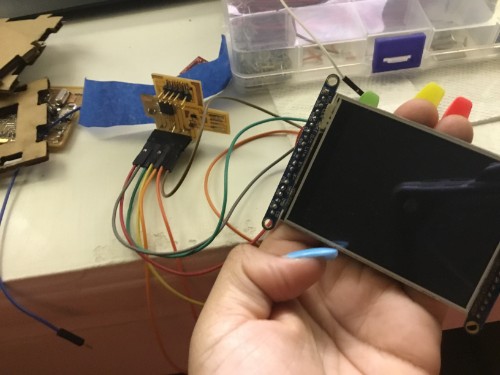
I used the same graphicstest code that can be found on my final project page. I followed the instructions on the SPI mode instructions page.
- Firstly, I soldered closed IM1, IM2, and IM3.
- I wired the pins correctly.
Wiring

Wiring up the display in SPI mode is much easier than 8-bit mode since there are way fewer wires.
Start by connecting the power pins. 3-5V Vin connects to the Arduino 5V pin.
GND connects to Arduino ground. CLK connects to SPI clock. On Arduino Uno/Duemilanove/328-based, thats Digital 13. On Mega's, its Digital 52 and on Leonardo/Due its ICSP-3. MISO connects to SPI MISO. On Arduino Uno/Duemilanove/328-based, thats Digital 12. On Mega's, its Digital 50 and on Leonardo/Due its ICSP-1.
MOSI connects to SPI MOSI. On Arduino Uno/Duemilanove/328-based, thats Digital 11.
On Mega's, its Digital 51 and on Leonardo/Due its ICSP-4. CS connects to our SPI Chip Select pin.
We'll be using Digital 10 but you can later change this to any pin D/C connects to our SPI data/command select pin. We'll be using Digital 9 but you can later change this pin too.

That's it! You do not need to connect the RST or other pins for now.
-
I had already installed the proper libraries (Adafruit ILI9341 and the Adafruit GFX Library because of my final project.
-
From inside of the ILI9341 library, I pulled up
graphicstestand uploaded it. Once it had been successfully uploaded, I ran the code, and it worked! One thing to note though, before I successfully got it to run, I had selected the wrong port, programmer, and chip, so it got REALLY hot. I had to let it cool for about 3 mins once I’d realized my mistake.
My files:
Group Assignment
Here is our group assignment for this week.
Takeaway
This week forced me to learn so much about electronics and electronic production to make something visually happen on a separate device. If I had to do one thing differently, I probably would stray away from using the USB port and maybe attach an FTDI port instead.