Final Project
Summary
For my final project, I made a northern circumpolar constellation reflector that recieves data from a GPS and utilizes that data to scroll the constellations in real-time on an LCD display. My device is encased by CNC-cut 1/2” plywood frames along with a laser-cut acrylic screen to protect the display. It incorpates 3D printed hooks for the wires and a vinyl sticker of an astronaut.
Slide
Video
Presentation
Watch my classmate William Zhou and I present our final projects from 57:30 - 1:03:41!
20200715 projects from Academany on Vimeo.
In an earlier week, I decided I would use a Creative Commons-Attribution-NonCommercial-ShareAlike 4.0 International License (CC BY-NC-SA 4.0). This license allows others to copy, alter, and/or share my work under the requirement that they give me credit, do not use my work for commercial purposes, and use the same license on their transformed project as my original. Although I came up with the idea of having a physical device, I was inspired by constellation-projection apps. I made this project to share my interest in constellations with the world and to also learn a lot of new information about astronomy. Therefore, I want to have my process in creating the reflector open and accessible for everyone.

Bill of Materials
| Item | Price |
|---|---|
| Adafruit 2.8” and 3.2” Color TFT Touchscreen Breakout v2 | $29.95 |
| Ultimate GPS Breakout v3 | $39.95 |
| ATMEGA328P-AUR microcontroller | $2.08 |
| 1/2” plywood | - |
| 1/8” acrylic | - |
Total: $71.98*
*Because most materials were available at the lab, I only had to buy the display.
The idea
Originally, I wanted to create a constellation chart which displays constellations directly from the user’s sky depending on where they are in the world. After various changes, I made a circumpolar constellation relfector which shows the (although the number is still being discussed) 6 northern circumpolar constellations along with Lynx. I chose to incorporate Lynx as well because it remains in the sky almost as long as the circumpolar constellations. Also, there would be a big gap between Camelopardalis and Ursa Major if I didn’t include it. I used a 2.8” TFT LCD screen to display the constellations, a self-modified satshakit to program the LCD, and an Ultimate GPS Breakout Board v3 to load the date and time.
Here was my initial sketch:
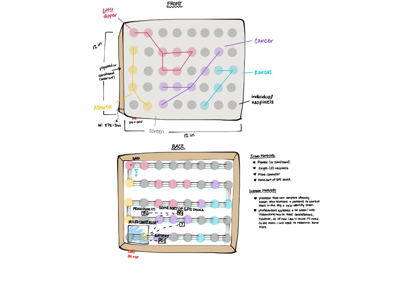
I did not make another sketch as my plans changed. Instead, I made impromptu decisions based on what I thought was best at the time.
Necessary Research
Before diving into this project, I needed to do some necessary research on specific design and process elements.
Constellations
I wanted the project to reflect any constellation formation above the user, but I quickly found that that would be above my expertise at the moment. Scrapping that portion, I still wanted to stick with the plan of having a set number of constellations, but I knew that the way I did this would have to change because I would only have a limited number of LEDs. After discussing with Dr. Harris about this, but, my first thought was to split the constellations shown by the northern and southern hemispheres. I wanted the device to identify where the user was (either in the northern or southern hemisphere) and then show a couple of constellations from each. This way, there would be preset constellations, and depending on the location of the user, the device would display one of the two sets. This was all fine and dandy until I learned that there were about 36 constellations in the northern sky and 52 in the southern sky. So, 88 in total. I would have to embed the coordinates of 88 constellations. Yeah,no ♡.
After researching more, I found that there are special constellations called ‘circumpolar constellations.’ 5 appear in the northern hemisphere and 3 in the southern, making 8 in total.
Sites I used to learn more about them: Astro4Dev Adiron Sky Center Constellation Guide
APIS (although I ended up not needing them)
Back to the subject of APIs, I have no idea what they are nor how to use them. After doing a quick search on YouTube, I found these videos:
Synopsis of this video by MuleSoft Studios explaining what they are:
- API: Application Programming Interface
- They function as the messenger and take requests to tell a system what you want it to do and then gives you back the response
- Create connectivity between many systems
Video by WebConcepts:
- REST API: Representational State Transfer
- HTTP Request Methods: Get and Post
- Get: Use it to consume data in order to get data back from the API - ex: passing URL parameters
- Post: Write data to the API - put data in the body of the request, have to install an extension (Postman Client)
If I wanted to implement an API(s) into my project, I would need to implement a WiFi module like the ESP8266. By doing this, I would gain access to all of the information on a website in which I could interface with my project. However, I would need to find the most suitable website for this that contained all the information I need. Dr. Harris mentioned that I could use Stellarium for this, but this would the most complicated method of using Stellarium.
LCDs
I have decided to use this screen officially. In terms of how I will frame it - I don’t know. As of now, I am thinking of maybe having it supported on a flat tray-like outer frame, but I don’t know where I would put the actual electronics if I went through with this.
This screen will allow me to potentially add color to the constellations which is something that I’ll decide after making sure this project works.
The constellations will appear in a long strip and move as time passes in reference with the orbit of the Earth around the sun. In order to get the constellations onto the screen, I have many options, but Dr. Harris helped me narrow it down into two.
METHOD 1:
“You’d use a picture to guide your star positioning, (maybe a screenshot from a program like stellarium which could give you some great images with lots of neat options like outlines, or prettier ghost figures, or star names listed) but then bring the screenshots into Gimp or Photoshop. Simply draw the midnight position of the stars. Save that file as 0.bmp. Then rotate it 15 degrees and save that as 1.bmp, rotate another 15 degrees and save the file as 2.bmp. Once you have all 24 BMPs (and of course you could do more for more updates per day than once an hour.) save them on an SD card. Use the arduino to read the SD card and load the appropriate BMP to the corresponding hour using the Adafruit_GFX library like this. Essentially this is a very slow powerpoint presentation that updates the slides one at a time and restarts at midnight. You can get more than 1 update an hour, but it’ll depend on how many rotations you saved files of. For instance, you can update every 30 minutes, but you’d need to rotate the images at 7.5 degrees for each file saved. You can see how 10 minutes and 5 minute and even 1 minute breakdowns can be done this way. Stellarium can actually model these rotations for you, but you still need to convert them into BMP file format for the arduino to be able to read. Loading BMP images takes a bit of time and that’s obvious on the screen when you are updating from one image to another. Check out the refresh rate on this tutorial which uses similar LCDs and OLEDs using the adafrtuit GFX library. Note, you’d have to do the same number of images for the northern and southern hemispheres and you’d have to save them with a different filename (n1.bmp, n2.bmp for northern and s1.bmp, s2.bmp for southern perhaps).””
In this method, he was asking me to create bitmap image of each constellation which would eventually flash on the screen like a slideshow. I used the slideshow approach as a starting off point for this project later on because it was the simplest one to understand. If I started out with the method that I understood the most, I could then advance onto the more complicated methods, following Dr. Harris’s thought process as well.
METHOD 2:
“This method would be a black and white screen in is simplest form but you can add colors once you get the basic implementation. You have a black background and you’d draw white or colored circles to represent the stars and you could even draw lines connecting the circles. You program the midnight position of the stars to be drawn on the screen directly on the arduino (no bitmap images). To do this, essentially you’d know the X and Y coordinates of the stars you want to represent on the screen’s pixels and program it to draw circles at those locations. While this sounds hard, it isn’t. You can use graph paper and use a smaller grid to get your X and Y for the star positions as I mentioned before, then we can scale the image up to the resolution of the LCD screen. It actually takes the arduino less time to do this than to update the entire screen to show a bitmap image so it’ll render faster on screen than method 1. This screen has a resolution of 240 tall x 320 wide which is almost 80,000 pixels so drawing even 100 stars will take much less time than filling each pixel with color form a BMP. Once we know what that midnight image looks like, we manually apply the exact same math to the X and Y locations of the circles that Gimp or Photoshop would do in method 1 above, but we do it in the Arduino. This will require some linear algebra (matrix math) but it isn’t scary. A little translation and rotation of the X,Y location of each star. Again, you’d need the list of all the stars positions for the northern and the southern hemispheres. The result is a smoother rotation than Method 1.”
I thought through multiple versions of this project.
Neopixel Version - Mr. Gershenfeld reccomended that instead of using neopixels, I build them myself using LEDs and processors, so it is more cost-effective. Honestly, I have no clue how I am going to go about this. To gather more information on neopixels, how they are made, and how I can replicate them, I referenced this website:
My teacher, Mr. Rudolph mentioned that I could use a neo pixel array instead for the sake of convience which, at the time, I thought I was going to do. He also suggested using APIs to gather the coordination of the stars.
Monochrome OLED version - As I have been doing more research, my plan has changed a lot. One thing that I am quickly realizing is that I do not have that much time before final presentations, so I have to hurry up and start making decisions on how I am going to complete this project. Am I stressed? A bit.
I talked to one of my teachers, Dr. Harris (HUGE thank you to him for his reccomendations and help) and he reccomended that instead of neopixels, I could potentially use a small OLED screen. Now this was a complete change. Throughout this entire process, I had been focusing on using neopixels - maybe buying a grid or strips, I wasn’t really sure. Using this small screen would completely change the shape, look, and all my original plans for this project.
Honestly, this is a change I am willing to make. Firstly, it would allow the constellations to be more recongizable and, secondly, they appear better in both the day time and night time. Unfortunately, though, I would not be able to implement my input device using the OLED screen.
Ultimately, I had to change many key points from the original design.
-
shape: In my first sketch, and CAD models, I envisioned this project in a box form. Although I could still make a big box, a smaller screen has the option of being wearable.(Thank you Dr. Harris for the idea)
-
look: I wanted each constellation that appeared to be color coded, but using a monochrome OLED screen would make this impossible for obvious reasons. This isn’t a big issue as it was just something that I thought would be cool.
-
input device: A GPS or WiFi Module that allows me to access date and time data
-
output device: the TFT LCD screen
To get started, I decided to test out the lcd to get familiar with it.
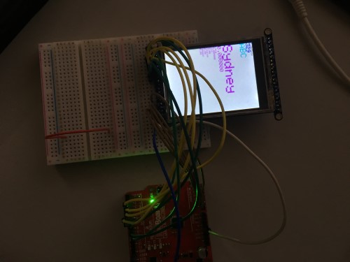
Once my LCD came in, I immediately got to work with it. I first needed to see if the LCD actually worked. I went onto the Adafruit page for the screen and followed their tutorial here for how to wire it. This is where I ran into my first issue. The backlight was not turning on. It only required ground and power to be wired and the board to be plugged in to come on, but it just wasn’t. I tried making breadboard rails and also directly wiring it, but both didn’t seem to work. The picture showed the Uno being powered from the DC port, but I was using the USB port. I switched to the DC port and attached a 9V battery, yet it still did not turn on. At this point, I was getting frustrated because I had spent a solid chunk of time working on something seemingly so simple. I asked Mr. Rudolph for help and he noticed that the pins on the LCD were not even connected to the board itself. Whoever had soldered them just added a blob of solder on the top and had not even thought to check if the solder was actually attaching to the metal.
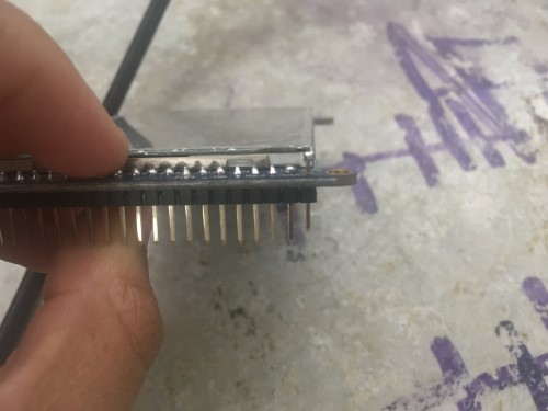
I went in and fixed all of the poorly soldered pins and plugged the board back in. It turned on!
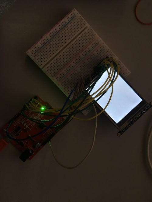
From here, I wanted to try and display something, as that was the next step on the beginner tutorial. After wiring everything on the breadboard to the Arduino, downloading the correct libraries, and pulling up the example code graphicstest, I plugged in the FTDI cable again and clicked upload. It did not work.
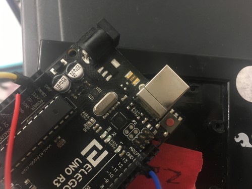
I checked my set up in Arduino and I had selected the Arduino Uno as my board, the ArduinoISP as my programmer and COM1 as my port. I didn’t see anything wrong with it, so I kept trying to upload. 20 minutes went by. Then it turned into 30 and then 1 hour. Let’s just say I did the same thing with a few minor tweaks for way too long. During this time, I looked at some online forums to try and find some solutions, but I could not. I repeated kept getting an error that my programmer was incorrect. I was using the Elegoo Uno R3 which was supposed to work the same as an Arduino Uno, so I assumed that it was correct to use the ArduinoISP programmer…I later found out that my assumption was wrong.
Again, I went to my teacher, Mr. Rudolph, because I had done many trials and many errors as much as I possibly could. He immediately noticed that judging from the error I was getting, the wrong programmer was selected (duh, Sydney). He informed me that even for boards that are similar to the Arduino, you can’t use the ArduinoISP as your programmer because you aren’t actually using an Arduino. Instead, I needed to use the AVR ISP.
I selected the AVR ISP, but the program still would not upload. We did not wait for an error message to pop up because it simply was taking way too long, so we knew that something was wrong. He had me check the COM port again, and saw another issue. COM1 is an internalized port and will never be the serial port that is supposed to be selected. The main issue that was happening was that no other COM port was showing up. It was only COM1. We tried plugging the board into both USB ports in the front of the computer and also the one in the back, but nothing other than COM1 showed up.
After taking a closer look at the the Uno, Mr. Rudolph noticed that two vital parts of the board had blown up/were chipped in the middle which was causing major issues (obviously).
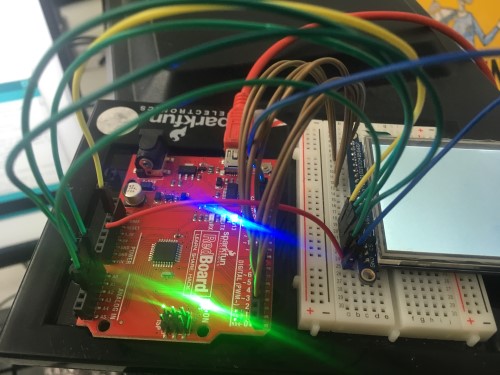
The board was unusable, hence the various issues, so he got me a new one - this one being a RedBoard. I hooked up the wires again and selected the right COM port that appeared. Before uploading the code again, I plugged in the board, and like the pictures on the guide, the LED beside pin 13 flashed along with the ‘ON’ LED. Before, the pin 13 LED had not flashed, which I had noticed, but ignored. There were so many red flags that I ignored. Hey, it’s a learning experience.
I uploaded the code and hey, hey, hey, it worked!
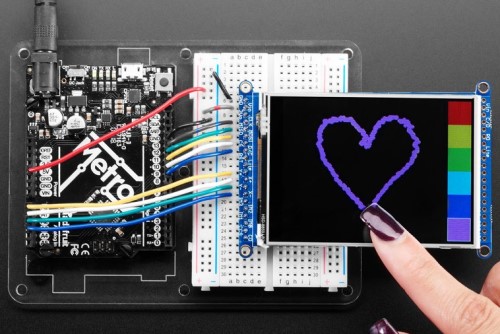
Now I wanted to test the touch screen.
The LCD I had ordered (the Adafruit 2.8” and 3.2” Color TFT Touchscreen Breakout v2) was a touch screen!
In my original plan, I did not see myself incorporating this feature or even using an LCD, but my idea could change at some point, so I decided to try it out,
Following the picture provided, I wired up the LCD for the resistive touch screen, and uploaded the new example code stated. It worked!
Figuring Out the Details
Like I mentioned earlier, my project is centered around the programming of the LCD. With the due date approaching rapidly, I needed to figure out this program quickly, so that I could run multiple tests and enhance the project.
I created this code my combining the graphicstest example in the TFTLCD library and a code example from the tinyGPS library. Basically, what I wanted to do was display the longitude, latitude, date, time and speed on the LCD. The graphicstest example helped me learn how to display text and the tinyGPS example provided the information.
#include <Adafruit_GFX.h>    // Core graphics library
#include <Adafruit_TFTLCD.h> // Hardware-specific library
#include <TinyGPS++.h> // Include the TinyGPS++ library
TinyGPSPlus tinyGPS; // Create a TinyGPSPlus object
#define GPS_BAUD 9600 // GPS module baud rate. GP3906 defaults to 9600.


#define LCD_CS A3 // Chip Select goes to Analog 3
#define LCD_CD A2 // Command/Data goes to Analog 2
#define LCD_WR A1 // LCD Write goes to Analog 1
#define LCD_RD A0 // LCD Read goes to Analog 0

#define LCD_RESET A4 // Can alternately just connect to Arduino's reset pin

// color names to values
#define  BLACK   0x0000
#define BLUE    0x001F
#define RED     0xF800
#define GREEN   0x07E0
#define CYAN    0x07FF
#define MAGENTA 0xF81F
#define YELLOW  0xFFE0
#define WHITE   0xFFFF

Adafruit_TFTLCD tft(LCD_CS, LCD_CD, LCD_WR, LCD_RD, LCD_RESET);

#define gpsPort ssGPS  // Alternatively, use Serial1 on the Leonardo

// If you're using an Arduino Uno, RedBoard, or any board that uses the
// 0/1 UART for programming/Serial monitor-ing, use SoftwareSerial:
#include <SoftwareSerial.h>
#define ARDUINO_GPS_RX 0 // GPS TX, Arduino RX pin
#define ARDUINO_GPS_TX 1 // GPS RX, Arduino TX pin
SoftwareSerial ssGPS(ARDUINO_GPS_TX, ARDUINO_GPS_RX); // Create a SoftwareSerial

#define gpsPort ssGPS  // Alternatively, use Serial1 on the Leonardo

void setup(void) {
  Serial.begin(9600);
  Serial.println(F("TFT LCD test"));

gpsPort.begin(GPS_BAUD);


#ifdef USE_ADAFRUIT_SHIELD_PINOUT
  Serial.println(F("Using Adafruit 2.8\" TFT Arduino Shield Pinout"));
#else
  Serial.println(F("Using Adafruit 2.8\" TFT Breakout Board Pinout"));
#endif

  Serial.print("TFT size is "); Serial.print(tft.width()); Serial.print("x"); Serial.println(tft.height());

  tft.reset();

  uint16_t identifier = tft.readID();

  if(identifier == 0x9325) {
    Serial.println(F("Found ILI9325 LCD driver"));
  } else if(identifier == 0x9328) {
    Serial.println(F("Found ILI9328 LCD driver"));
  } else if(identifier == 0x7575) {
    Serial.println(F("Found HX8347G LCD driver"));
  } else if(identifier == 0x9341) {
    Serial.println(F("Found ILI9341 LCD driver"));
  } else if(identifier == 0x8357) {
    Serial.println(F("Found HX8357D LCD driver"));
  } else {
    Serial.print(F("Unknown LCD driver chip: "));
    Serial.println(identifier, HEX);
    Serial.println(F("If using the Adafruit 2.8\" TFT Arduino shield, the line:"));
    Serial.println(F("  #define USE_ADAFRUIT_SHIELD_PINOUT"));
    Serial.println(F("should appear in the library header (Adafruit_TFT.h)."));
    Serial.println(F("If using the breakout board, it should NOT be #defined!"));
    Serial.println(F("Also if using the breakout, double-check that all wiring"));
    Serial.println(F("matches the tutorial."));
    return;
  }

  tft.begin(identifier);

  Serial.println(F("Benchmark                Time (microseconds)"));

  Serial.print(F("Screen fill              "));
  Serial.println(testFillScreen());
  delay(500);

  Serial.print(F("Text                     "));
  Serial.println(testText());
  delay(3000);

  Serial.println(F("Done!"));
}

void loop(void) {
  for(uint8_t rotation=0; rotation<4; rotation++) {
    tft.setRotation(rotation);
    testText();
    delay(2000);
  }
}

unsigned long testFillScreen() {
  unsigned long start = micros();
  tft.fillScreen(BLACK);
  tft.fillScreen(MAGENTA);
  tft.fillScreen(BLUE);
  tft.fillScreen(GREEN);
  tft.fillScreen(BLACK);
  return micros() - start;
}

unsigned long testText() {
  tft.fillScreen(BLACK);
  unsigned long start = micros();
  tft.setCursor(0, 0);
  tft.setTextColor(WHITE);  tft.setTextSize(1);
  tft.println("Sydelbow");
  tft.setTextColor(YELLOW); tft.setTextSize(2);
  tft.println(329);
  tft.setTextColor(RED);    tft.setTextSize(3);
  tft.println(0xABC, HEX);
  tft.println();
  tft.setTextColor(GREEN);
  tft.setTextSize(5);
  tft.println("Sydney");
  tft.setTextSize(2);
   tft.println(tinyGPS.location.lat(), 6);
  tft.setTextSize(1);
  tft.println("Long: "); tft.println(tinyGPS.location.lng(), 6);
  tft.println("Alt: "); tft.println(tinyGPS.altitude.feet());
  tft.println("Course: "); tft.println(tinyGPS.course.deg());
  tft.println("Speed: "); tft.println(tinyGPS.speed.mph());
  return micros() - start;
}
It worked! All the information was displayed, and I even added in my own name + nickname as you can see in the last function above.
Embedded Programming (Making the Constellations Show Up + Timing Them Correctly)
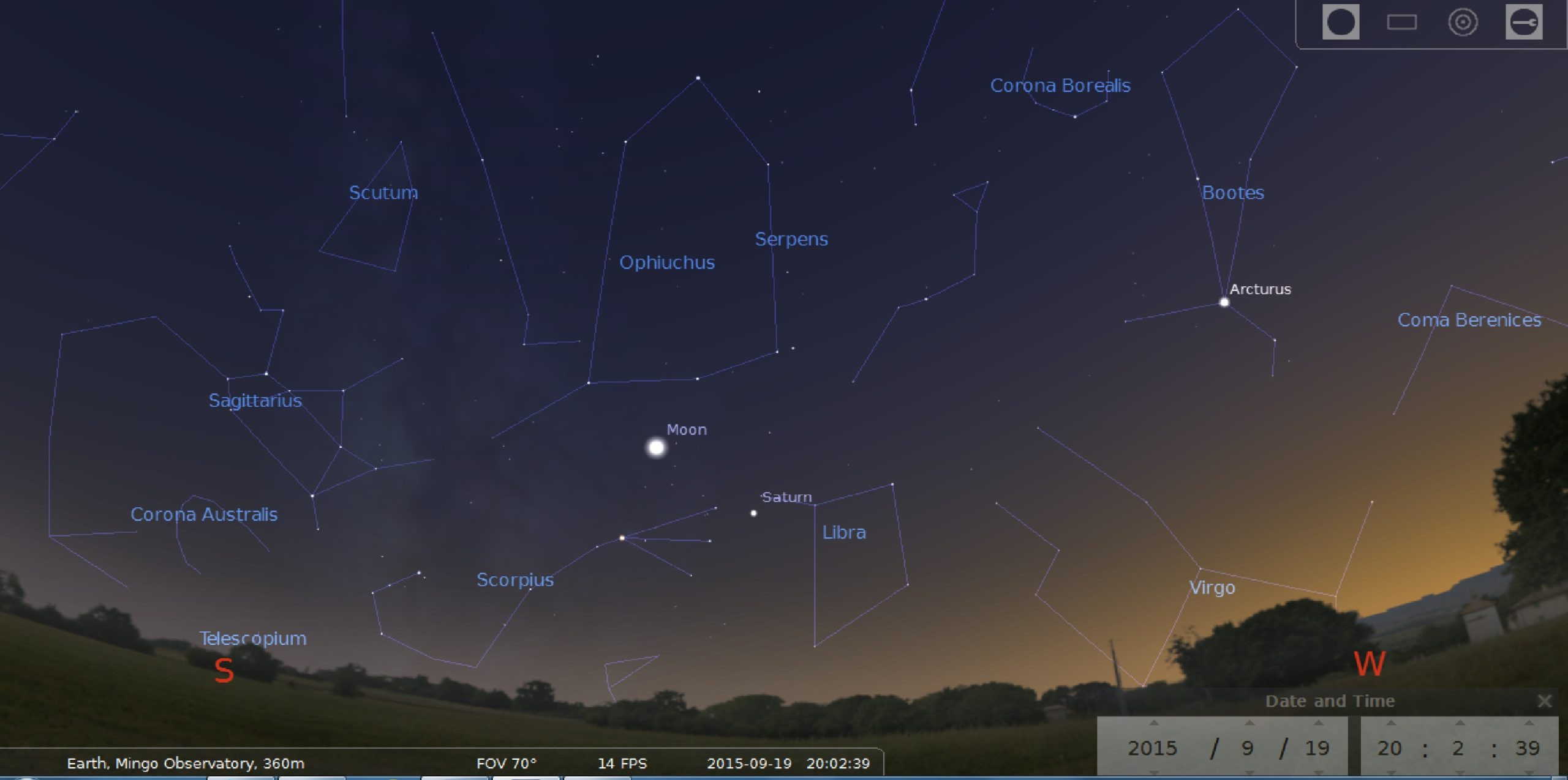
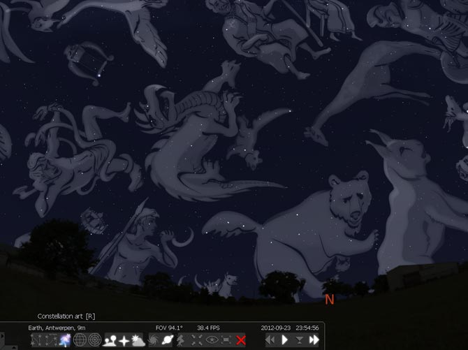
Although I could just start out by calculating the coordinates of the constellations, I wanted to first try out the bitmapping method my teacher, Dr. Harris, explained to me. Since receiving this email, I have decided to not do the southern circumpolar constellations because the northern constellations are more relative to where I live, so I could show the device working. Following his instructions, I took a screenshot of Ursa Minor in Stellarium, and then,using the given photo editor, changed the background to black and the outline of the little dipper to white.
From there, I put it into Paint.net and made sure the canvas size was smaller than my display. The LCD is 240x320, so I resized the image to 240x316. According to the video, I only needed to “call” the bitmap in order to display the image. Looking at the man in video’s code combined with the ‘graphicstest’ example in the Adafruit TFTLCD library, I generated this code:
#include <Adafruit_TFTLCD.h>
#include <Adafruit_GFX.h>

#define LCD_CS A3
#define LCD_CD A2
#define LCD_WR A1
#define LCD_RD A0
#define LCD_RESET A4

#define BLACK   0x0000
#define BLUE    0x001F
#define RED     0xF800
#define GREEN   0x07E0
#define CYAN    0x07FF
#define MAGENTA 0xF81F
#define YELLOW  0xFFE0
#define WHITE   0xFFFF
#define GREY     0xD6BA

Adafruit_TFTLCD tft(LCD_CS, LCD_CD, LCD_WR, LCD_RD, LCD_RESET);

extern uint8_t ursaminor[];

void setup() {
  Serial.begin(9600);
  tft.fillScreen(BLACK);

  Serial.print("TFT size is "); Serial.print(tft.width()); Serial.print("x"); Serial.println(tft.height());
}
void loop() {

}
 void drawUrsaMinor()
{
  tft.drawBitmap(0,30,ursaminor,316,240,YELLOW);
}
I had already made a page with the bitmap code, so I could call it in the code shown above. That code will be grouped in my files (under the name ursaminor_bmp) at the bottom of this section because the code is a bit lengthy.
I uploaded the code onto the LCD twice but nothing showed up each time. I revisited the Adafruit page for the display and found a page that clearly explains how I can upload bitmap images. I was using the 8-bit mode instead of SPI.
Instead of putting more energy into bitmapping images, I switched gears to Method 2. This was the method that ended up working in the end.
To start off, Dr. Adam Harris was a huge help during all of this, so thank you so much to him for his help. He guided me in the right direction but left me to figure out issues on my own.
The first thing I needed to do was draw the constellations out in a linear pattern. I thought of it like a map. I was going to be taking something from a spherical pattern and making it flat. I used the azithumal map on Stellarium to help me with this. Although the constellations were going to inevitably be off because of how the display is shaped, I wanted them to be as close as possible. To do this, I looked at the positions of the stars in the constellations and recreated their exact angles visually. I went into Excel and drew them all out in a scaled down grid from 240x320 - the actual size of the LCD. Once they looked good enough for me, I moved on.
- Starstrip (will be included in full compilation of files)
Next, I needed to get the coordinates of the starts in the constellations. In those places, I would draw stars to represent constellations and put lines in between them to display their actual formation.
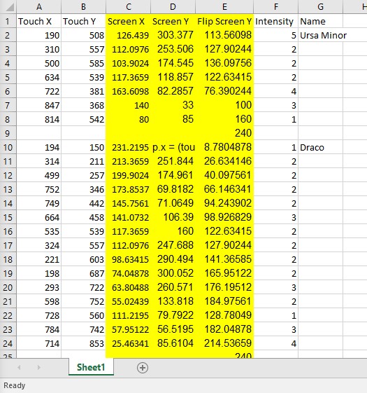
Dr. Harris came up with the splendid idea of utilizing the touch screen for this part. All I needed to do was load up tftpaint, make dots wherever the stars in the constellations were, and record them.
This seemed simple enough, so I did that for every constellation.
I retrieved their coordinates and wrote them down in an Excel file (which will also be included in the complete zip file at the bottom of this page labeled “coordinates”). I retreived their coordinates and wrote them down in an Excel file. I didn’t know how to actually write the constellations, so I looked back at graphicstest to see how adafruit wrote them.
These lines:
tft.fillCircle(x,y,x1,y1);
tft.drawLine(MAGENTA);
tft.fillScreen(BLUE);
were what I used the most during this part. Because I did not know if the coordinates would actually show up yet, I only wrote Ursa Minor’s values in first. I’m very happy I did this because when I uploaded the code, nothing appeared. I rechecked my numbers a bazillion times and tried to thing of possible errors, but I just couldn’t.
Here was my code:
#include <Adafruit_GFX.h>
#include <Adafruit_TFTLCD.h>

#define LCD_CS A3
#define LCD_CD A2
#define LCD_WR A1
#define LCD_RD A0

#define LCD_RESET A4

#define  BLACK   0x0000
#define BLUE    0x001F
#define RED     0xF800
#define GREEN   0x07E0
#define CYAN    0x07FF
#define MAGENTA 0xF81F
#define YELLOW  0xFFE0
#define WHITE   0xFFFF

Adafruit_TFTLCD tft(LCD_CS, LCD_CD, LCD_WR, LCD_RD, LCD_RESET);

void setup(void) {
  Serial.begin(9600);
  Serial.println(F("Star test"));

  Serial.print("TFT size is "); Serial.print(tft.width()); Serial.print("x"); Serial.println(tft.height());

  tft.reset();

  uint16_t identifier = tft.readID();

  tft.begin(identifier);

  Serial.print(F("Lines                    "));
  Serial.println(testLines(WHITE));
  delay(500);

}

void loop(void) {
  for(uint8_t rotation=0; rotation<0; rotation++) {
    tft.setRotation(rotation);
    delay(2000);
  }
}

  unsigned long testLines (uint16_t color) {
  unsigned long start, t;
  int           x1, y1, x2, y2,
                w = tft.width(),
                h = tft.height();


tft.fillScreen(BLACK);

//Ursa Minor
tft.drawLine(190, 508, 310, 557, WHITE);
tft.drawLine(500, 585, 634, 539, WHITE);
tft.drawLine(722, 381, 847, 368, WHITE);
tft.drawLine(814, 542, 634, 539, WHITE);
}
//Draco
//tft.drawLine(x1, y1, x2, y2, color);
//tft.drawLine(x1, y1, x2, y2, color);
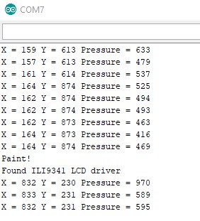
I seeked out Dr. Harris’s help and he was stumped at first too. It should’ve been working. These were the display coordinates from where I tapped on the screen - or so we thought. Dr. Harris then realized that sometimes touchscreen LCD’s scale the number of pixels up or down depending on the action that is done. This means that there would be a function in the code that we used that did this. He also took into account that some of the numbers I’d collected were out of range for the display. It is only 240x320, but I was getting data in the 400s-700s for some.
We went back into tftpaint and found this function:
// scale from 0->1023 to tft.width
p.x = map(p.x, TS_MINX, TS_MAXX, tft.width(), 0);
p.y = map(p.y, TS_MINY, TS_MAXY, tft.height(), 0);
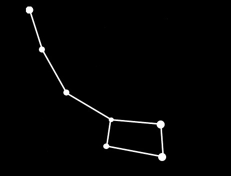
which scales all of the numbers that I recieved up. Now, I just had to reverse it. I am very thankful that Dr. Harris had me make this list in Excel because I could just apply the reversal math to one column and then drag it down to the others. I did this to all of the values and it uploaded.....but Ursa Minor was upside down. I discovered that I had entered in the wrong math for each side, so I had to flip it another time.
Here, Dr. Harris taught me how to pull up a graph to see if the coordinates we had looked anything like Ursa Minor. They did, so we figure the new data was correct.
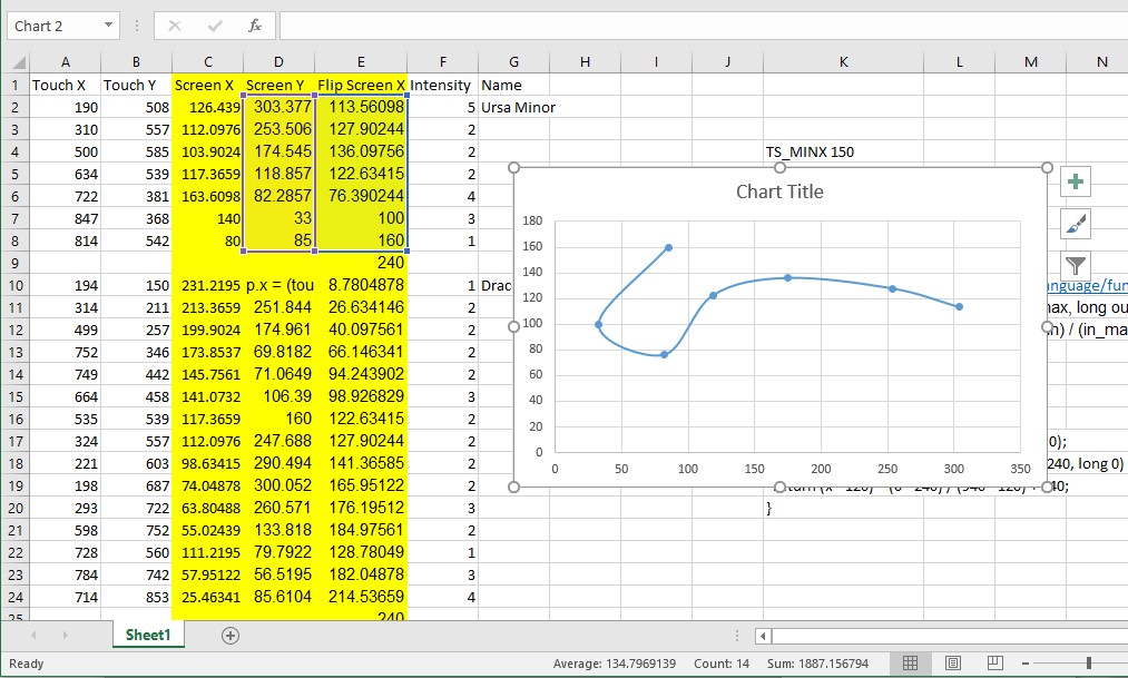
Once I had dealt with the flipping ordeal, I needed to rewrite the coordinates for every other constellation. This did not take as long because I had already applied the math for all of the columns below the first one I did it too. Thanks, Excel, for that cool feature!
This was the first code a I created. I referenced graphicstest for the set up (which libraries to include, which pins go where, etc.) but other than that, this was my own creation. I left out the set up below because it was a direct copy of graphicstest, however, if you want to see the full code, it is included in the final .zip.
Adafruit_TFTLCD tft(LCD_CS, LCD_CD, LCD_WR, LCD_RD, LCD_RESET);

void setup(void) {
  Serial.begin(9600);
  Serial.println(F("TFT LCD test"));
}

void loop(void) {
/*
tft.fillScreen(BLACK);
Serial.println("Made screen black");
//Ursa Minor
//  tft.fillCircle(x, y, radius, color);

tft.fillCircle(46, 74, 5, GREEN);
tft.drawLine(46, 74, 66, 81, GREEN);
Serial.println("Drew Line 1");

tft.fillCircle(66, 81, 2, BLUE);
tft.drawLine(66, 81, 98, 86, BLUE);
Serial.println("Drew Line 2");

tft.fillCircle(98, 86, 2, MAGENTA);
tft.drawLine(98, 86, 120, 79, MAGENTA);
Serial.println("Drew Line 3");

tft.fillCircle(120, 79, 2, YELLOW);
tft.drawLine(120, 79, 135, 55, YELLOW);
Serial.println("Drew Line 4");

tft.fillCircle(135, 55, 4, RED);
tft.drawLine(135, 55, 154, 67, RED);
Serial.println("Drew Line 5");

tft.fillCircle(154, 67, 3, ORANGE);
tft.drawLine(154, 67, 134, 97, ORANGE);
Serial.println("Drew Line 6");

tft.fillCircle(134, 97, 1, CYAN);
tft.drawLine(134, 97, 120, 79, CYAN);
Serial.println("Drew Line 6");

delay(5000);


int shift=0;
//Draco
tft.fillCircle(46, 8, 1, GREEN);
tft.drawLine(46, 8, 86, 26, GREEN);
Serial.println("Drew Line 1");

tft.fillCircle(86, 26, 2, BLUE);
tft.drawLine(86, 26, 148, 40, BLUE);
Serial.println("Drew Line 2");

tft.fillCircle(148, 40, 2, MAGENTA);
tft.drawLine(148, 40, 225, 62, MAGENTA);
Serial.println("Drew Line 3");

tft.fillCircle(225, 62, 2, YELLOW);
tft.drawLine(225, 62, 231, 94, YELLOW);
Serial.println("Drew Line 4");

tft.fillCircle(231, 94, 2, RED);
tft.drawLine(231, 94, 202, 115, RED);
Serial.println("Drew Line 5");

tft.fillCircle(202, 115, 3, ORANGE);
tft.drawLine(202, 115, 160, 138, ORANGE);
Serial.println("Drew Line 6");

tft.fillCircle(160, 138, 2, CYAN);
tft.drawLine(160, 138, 89, 143, CYAN);
Serial.println("Drew Line 7");

tft.fillCircle(89, 143, 2, GREEN);
tft.drawLine(89, 143, 55, 157, GREEN);
Serial.println("Drew Line 8");

tft.fillCircle(55, 157, 2, BLUE);
tft.drawLine(55, 157, 47, 181, BLUE);
Serial.println("Drew Line 9");

tft.fillCircle(47, 181, 2, MAGENTA);
tft.drawLine(47, 181, 79, 192, MAGENTA);
Serial.println("Drew Line 10");

tft.fillCircle(79, 192, 3, YELLOW);
tft.drawLine(79, 192, 180, 200, YELLOW);
Serial.println("Drew Line 11");

tft.fillCircle(180, 200, 2, RED);
tft.drawLine(180, 200, 210, 183, RED);
Serial.println("Drew Line 12");

tft.fillCircle(210, 183, 1, ORANGE);
tft.drawLine(210, 183, 230, 193, ORANGE);
Serial.println("Drew Line 13");

tft.fillCircle(230, 193, 3, CYAN);
tft.drawLine(230, 193, 219, 230, CYAN);
Serial.println("Drew Line 14");

tft.fillCircle(219, 230, 4, CYAN);
tft.drawLine(219, 230, 180, 200, CYAN);
Serial.println("Drew Line 15");

delay(5000);

tft.fillScreen(BLACK);
Serial.println("Made screen black");

//Cepheus
tft.fillCircle(163, 115, 2, GREEN);
tft.drawLine(163, 115, 52, 30, GREEN);
Serial.println("Drew Line 1");

tft.fillCircle(52, 30, 2, BLUE);
tft.drawLine(52, 30, 75, 190, BLUE);
Serial.println("Drew Line 2");

tft.fillCircle(75, 190, 2, MAGENTA);
tft.drawLine(75, 190, 163, 115, MAGENTA);
Serial.println("Drew Line 3");

tft.fillCircle(163, 115, 3, YELLOW);
tft.drawLine(163, 115, 205, 210, YELLOW);
Serial.println("Drew Line 4");

tft.fillCircle(205, 210, 2, RED);
tft.drawLine(205, 210, 130, 300, RED);
Serial.println("Drew Line 5");

tft.fillCircle(130, 300, 2, RED);
tft.drawLine(130, 300, 75, 190, RED);
Serial.println("Drew Line 6");

delay(5000);

tft.fillScreen(BLACK);
Serial.println("Made screen black");

//Cassiopeia
tft.fillCircle(218, 166, 4, GREEN);
tft.drawLine(218, 166, 138, 210, GREEN);
Serial.println("Drew Line 1");

tft.fillCircle(138, 210, 4, BLUE);
tft.drawLine(138, 210, 108, 126, BLUE);
Serial.println("Drew Line 2");

tft.fillCircle(108, 126, 4, MAGENTA);
tft.drawLine(108, 126, 28, 169, MAGENTA);
Serial.println("Drew Line 3");

tft.fillCircle(28, 169, 3, YELLOW);
tft.drawLine(28, 169, 26, 78, YELLOW);
tft.fillCircle(26, 78, 2, YELLOW);
Serial.println("Drew Line 4");

delay(5000);

tft.fillScreen(BLACK);
Serial.println("Made screen black");

//Camelopardalis

tft.fillCircle(37, 289, 2, GREEN);
tft.drawLine(37, 289, 52, 240, GREEN);
Serial.println("Drew Line 1");

tft.fillCircle(52, 240, 1, BLUE);
tft.drawLine(52, 240, 74, 140, BLUE);
tft.fillCircle(74, 140, 2, BLUE);
Serial.println("Drew Line 2");

tft.fillCircle(139, 182, 1, MAGENTA);
tft.drawLine(139, 182, 74, 140, MAGENTA);
Serial.println("Drew Line 3");

tft.fillCircle(139, 182, 2, YELLOW);
tft.drawLine(139, 182, 190, 60, YELLOW);
Serial.println("Drew Line 4");

tft.fillCircle(139, 182, 2, CYAN);
tft.drawLine(139, 182, 37, 289, CYAN);
Serial.println("Drew Line 5");

delay(5000);
*/
tft.fillScreen(BLACK);
Serial.println("Made screen black");

//Lynx

tft.fillCircle(200, 20, 3, GREEN);
tft.drawLine(200, 20, 215, 60, GREEN);
Serial.println("Drew Line 1");

tft.fillCircle(215, 60, 2, BLUE);
tft.drawLine(215, 60, 205, 95, BLUE);
Serial.println("Drew Line 2");

tft.fillCircle(205, 95, 2, MAGENTA);
tft.drawLine(205, 95, 220, 115, MAGENTA);
Serial.println("Drew Line 3");

tft.fillCircle(220, 115, 2, YELLOW);
tft.drawLine(220, 115, 190, 150, YELLOW);
Serial.println("Drew Line 4");

tft.fillCircle(190, 150, 2, RED);
tft.drawLine(190, 150, 180, 200, RED);
Serial.println("Drew Line 5");

tft.fillCircle(180, 200, 1, ORANGE);
tft.drawLine(180, 200, 215, 230, ORANGE);
Serial.println("Drew Line 6");
/*
tft.fillCircle(62, 204, 3, CYAN);
tft.drawLine(62, 204, 26, 233, CYAN);
Serial.println("Drew Line 7");

tft.fillCircle(26, 233, 5, GREEN);
tft.drawLine(26, 233, 170, 45, GREEN);
Serial.println("Drew Line 8");
*/
delay(5000);

/*
tft.fillScreen(BLACK);
Serial.println("Made screen black");
*/
/*
//Ursa Major (Big Dipper)

tft.fillCircle(200, 17, 5, GREEN);
tft.drawLine(200, 17, 170, 45, GREEN);
Serial.println("Drew Line 1");

tft.fillCircle(170, 45, 4, BLUE);
tft.drawLine(170, 45, 130, 50, BLUE);
Serial.println("Drew Line 2");

tft.fillCircle(130, 50, 5, MAGENTA);
tft.drawLine(130, 50, 90, 60, MAGENTA);
Serial.println("Drew Line 3");

tft.fillCircle(90, 60, 2, YELLOW);
tft.drawLine(90, 60, 57, 117, YELLOW);
Serial.println("Drew Line 4");

tft.fillCircle(57, 117, 3, RED);
tft.drawLine(57, 117, 30, 82, RED);
Serial.println("Drew Line 5");

tft.fillCircle(30, 82, 3, ORANGE);
tft.drawLine(30, 82, 55, 45, ORANGE);
Serial.println("Drew Line 5");

tft.fillCircle(55, 45, 3, CYAN);
tft.drawLine(55, 45, 90, 60, CYAN);
Serial.println("Drew Line 5");

delay(10000);

tft.fillScreen(BLACK);
Serial.println("Made screen black");
*/
}// end loop
Errors in the Code above
-did not scroll, no function to tell it to do so
-no shift, again with the scrolling
-worked, but didn’t work. Only showed one constellation, then stopped
What was tedious though, was entering the numbers in twice. Because I wanted to create a scrolling version, Dr. Harris reccomended making two functions in my code which would look like these, but more in depth:
void drawCepheus() {
//Cepheus
tft.fillCircle(163, 115  + shift + 320, 2, GREEN);
tft.drawLine(163 , 115 + shift + 320, 52, 30 + shift + 320, GREEN);
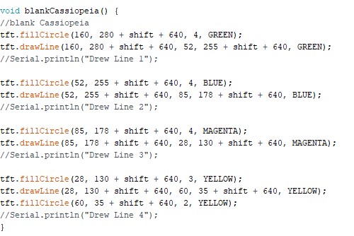
void blankCepheus() {
// blank Cepheus
tft.fillCircle(163, 115  + shift + 320, 2, BLACK);
tft.drawLine(163 , 115 + shift + 320, 52, 30 + shift + 320, BLACK);
Right after it draws the constellation, it will rewrite it as black so that the constellation looks like it is moving across the screen because I am using black as the background color to emulate space.
From this point on, it was very repetitive. I just had to look at the coordinates I’d created and create a draw and blank function for each of them. Because I was on auto-pilot mode, I made many mistakes during this part that would set me back a couple of hours later on. That’s okay, though because this was a good learning experience.
Next, I moved onto creating the shift values. The shift values would allow for the scroll to well, scroll. To do this, I made a function called “shift” and called it within each constellation function. “shift” equalled zero, so that I could change it wherever and have it reset fully.
int shift=0;
int shift2=0;
I also made a shift two because while creating this code, the sketch became too big for the arduino due the the sizes and amount of libraries that I was using.
My libararies:
#include <TinyGPS++.h>
#include <TinyGPS.h>

#include <Adafruit_GFX.h>    // Core graphics library
#include <Adafruit_TFTLCD.h> // Hardware-specific library
#include <SoftwareSerial.h>
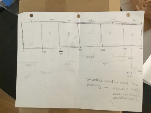
I also had to determine the framing of the constellations. What I mean by this is how they were going to smoothily scroll through the screen. I already had “shift” which was going to offset them by whatever number was called, but now I needed the number that would tell where they were going to be drawn first. Going down the line, starting at Ursa Minor and Draco, I would have to draw each constellation after UMi and D off the screen. Starting at 640, I added 320 to each “frame” which created the next shift values.
I went back in and added the numbers shown above to each of the constellations, so they looked like this:
void drawCepheus() {
//Cepheus
tft.fillCircle(163, 115  + shift + 320, 2, GREEN);
tft.drawLine(163 , 115 + shift + 320, 52, 30 + shift + 320, GREEN);

tft.fillCircle(52 , 30 + shift + 320, 2, BLUE);
tft.drawLine(52 , 30 + shift + 320, 75 , 190 + shift + 320, BLUE);

tft.fillCircle(75 , 190 + shift + 320, 2, MAGENTA);
tft.drawLine(75 , 190 + shift + 320, 163 , 115 + shift + 320, MAGENTA);

tft.fillCircle(163 , 115 + shift + 320, 3, YELLOW);
tft.drawLine(163 , 115 + shift + 320, 205 , 210 + shift + 320, YELLOW);

tft.fillCircle(205 , 210 + shift + 320, 2, RED);
tft.drawLine(205 , 210 + shift + 320, 130 , 300 + shift + 320, RED);

tft.fillCircle(130 , 300 + shift + 320, 2, RED);
tft.drawLine(130 , 300 + shift + 320, 75 , 190 + shift + 320, RED);
}

void blankCepheus() {
// blank Cepheus
tft.fillCircle(163, 115  + shift + 320, 2, BLACK);
tft.drawLine(163 , 115 + shift + 320, 52, 30 + shift + 320, BLACK);

tft.fillCircle(52 , 30 + shift + 320, 2, BLACK);
tft.drawLine(52 , 30 + shift + 320, 75 , 190 + shift + 320, BLACK);

tft.fillCircle(75 , 190 + shift + 320, 2, BLACK);
tft.drawLine(75 , 190 + shift + 320, 163 , 115 + shift + 320, BLACK);

tft.fillCircle(163 , 115 + shift + 320, 3, BLACK);
tft.drawLine(163 , 115 + shift + 320, 205 , 210 + shift + 320, BLACK);

tft.fillCircle(205 , 210 + shift + 320, 2, BLACK);
tft.drawLine(205 , 210 + shift + 320, 130 , 300 + shift + 320, BLACK);

tft.fillCircle(130 , 300 + shift + 320, 2, BLACK);
tft.drawLine(130 , 300 + shift + 320, 75 , 190 + shift + 320, BLACK);
}
(Only Cepheus for the sake of space, but imagine everyone looking like this with their own numbers)
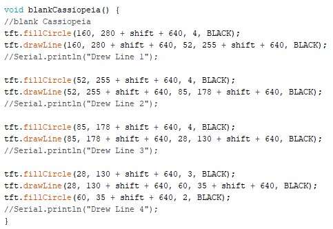
When I uploaded the code, all of the constellations were running, except Cassiopiea kept repeating. I tried everything. I literally sat there for hours adjusting the draw function and it’s shift values. That was my main mistake. I did - or I thought I did - check the blank function for Cassiopiea, but I later realized that I had been confusion Camelopardalis’s blank function with Cassiopeia’s. It turned out that I never changed Cass’s blank function’s colors to blank, hence why it was repeating in color.
Once I fixed that, the constellations were scrolling smoothily! Now, I needed to incorporate the GPS (my input device)
GPS
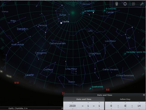
Here are the steps that Dr. Harris layed out for me:
***”Next Step 1. Figure out how many pixels you shift for 1 full rotation. This will tell you how many pixels represent 360 degrees.
To calculate the current overhead constellation, we’ll have to start at a specific time and date. Looking in Stellarium at January 1st 2020 at midnight (UTC) for the location of 0 degrees longitude, it looks like Lynx is directly overhead and centered. That’s our starting reference point. Lynx = midnight, ursa Major = 3am, Minor and Draco = 9am, Cepheus is = 3pm, Cassiopeia = 6pm, Camelopardalis = 9pm,
(Most transitions take 3 hours with the exceptions of UrsaMajor to Draco and Draco to Cepheus, which take 6 hours.)
Next Step 2. There’s a bit more to incorporating the GPS values to the current screens you have. You’ll get the current date, UTC time, and longitude from the tinyGPS library. These will all be used to calculate the offsets from our reference point. The reference point is January 1 2020 at 12:00am at 0 degrees longitude. The code on this page will give you the number of minutes that have passed between 2 given dates. This is exactly what you need to figure out. https://forum.arduino.cc/index.php?topic=368049.15
Next Step 3. Calculate the Longitude offset to calculate timezone. We’ll ignore timezones and daylight savings time as these are purely political inventions and the universe doesn’t care about politics… This is really quite easy to calculate. GPS gives you a value from -180 to +180 for your long. Charlotte is -80 which means 80 degrees WEST of 0 degrees long. You need to map this number into -12 and +12 hours. Look up how to map numbers for arduino. To test it, you can enter -80 for the longitude in the input and the output of this will be Charlotte’s offset from UTC, which is -5 hours. That’s how you will know when you get it right. you can test for other cities as well.
Next Step 4. Combine the number of minutes offset and the longitude offset to determine the current shifted value.
Next Step 5. Fiddle and adjust the shift value and delay and pictures until they look like you want and you’re done.”***
Now, this all sounded great in theory, but I had no idea what to do for half of the steps. So, I walked myself through it.
Dr. Harris also found this function:
long JD(int year, int month, int day)
{ // COMPUTES THE JULIAN DATE (JD) GIVEN A GREGORIAN CALENDAR
  return day-32075+1461L*(year+4800+(month-14)/12)/4+367*(month-2-(month-14)/12*12)/12-3*((year+4900+(month-14)/12)/100)/4;
}

long daysDiff(int year1, int mon1, int day1, int year2, int mon2, int day2)
{
  return JD(year2, mon2, day2) - JD(year1, mon1, day1);
}

long minutesDiff(int year1, int mon1, int day1, int hour1, int min1, int year2, int mon2, int day2, int hour2, int min2 )

{
  int mDiff= (hour2*60+min2) - (hour1*60+min1);
  return daysDiff(year1, mon1, day1, year2, mon2, day2)*1440 + mDiff;
}
which takes the minute difference between one date and another and changes it into the days difference. This would be important if I wanted to create a day offset. I used January 1, 2020 as my reference date. On that day, Lynx was directly overhead.
This meant that Lynx would serve as my starting time. From Lynx to Ursa Major, it takes 3 hours. Each constellation takes three hours to rotate to the next one being directly overhead to the next. Ursa Major to Ursa Minor to Draco is the only oddball which takes 6 hours.
-Lynx = midnight -Ursa Major = 3am -Ursa Minor and Draco = 9am -Cepheus is = 3pm -Cassiopeia = 6pm -Camelopardalis = 9pm
NOTE One thing to note is that the code that I developed with Dr. Harris‘s help, does NOT account for leap years. This means that as time progresses, the reflector will become a little more off each year until it is not accurate at all. In the future, I would be nice to fix this, but for now, it is as accurate as can be!
CNC (Compputer Controlled Machining)
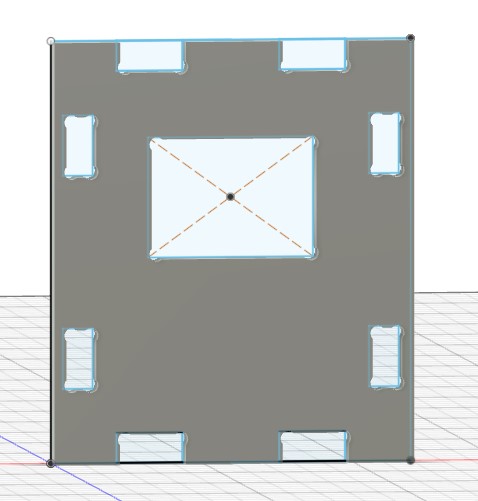
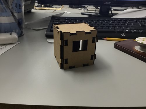
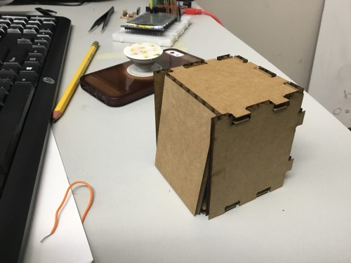
Like I mentioned earlier, I had some trouble coming up with what I wanted this device to look like ever since I switched from neopixels to an LCD. I decided on a box with a sliding back door for convienent access to the electronics incase there were any issues.
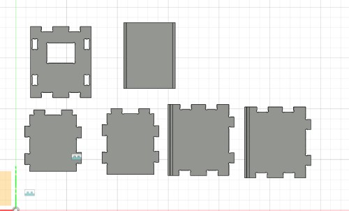
I used Fusion360 to design my pieces. I first went in and created a normal sketch of the shapes of the pieces, extruded them to the thickness of the wood (0.48 in). While creating the skteches, I made sure to be extremely careful to get the proper measurements correct because of the extreme mishaps that happened during week 8. Because I was creating a sliding door, I made sure that the bottom piece of the box extended fully back whereas the top didn’t to allow for the door. From there, I created the slots in the side pieces for the sliding back door and also created the divets in the back piece. I made the slots 0.26in and the pieces to fit in the sliding slots 0.23in to account for any shift in the side of the wood and also to ensure that the door would slide easily. I also dogboned all of the corners.
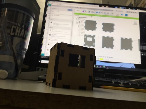
Before actually cutting, I made two scaled-down laser cut versions. These made it easy to notice issues with the fit of the pieces in a low-risk way. I first imported the Fusion sketch as a .DXF. into CorelDraw, and fixed any nodes that were not connected. The first time I imported the files, there were no dogbones, so I projected everything in Fusion as a separate sketch together and saved it directly from there. The dogbones appeared after that.
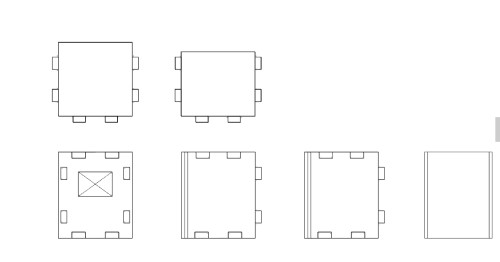
In the first model, the top didn’t fit because I had not accounted for the fact that both the top corner and the corner that the side and front pieces made could not be the same size. The top piece’s corner needed to be more narrow to fit inside. The same error was apparent for the bottom piece as well. I also noticed that the tabs and slots did not line up properly. Also, the slots in the front piece were too wide.
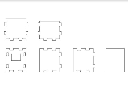
I made these portions slimmer, “corrected” the tabs and slots, and cut another model. However, everything was still so off.
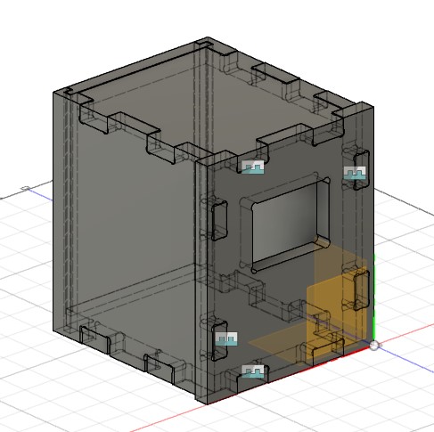
I enquired help from Mr. Rudolph and he came to the rescue. He taught me how to use the Geometry tool to project the top and bottom pieces from the side and front. Switching the view so that it was at a helicopter POV, he had me select all the top faces and then extrude them. This way,each piece without a doubt fit into the top and bottom. He also taught me how to use Offset Face. This tool made it very easy to create tolerances. Instead of manually creating them like I was doing before, now, with this instrument, I could just select two faces and more them toward or away from each other in an equal amount. Along with that, he showed me how to use the “Joint” tool, so that I could make a full scale model of my box and what it would look like. Previously, during CNC week, I had just kind of dragged the pieces to get a general sense of what they were supposed to look like. He demonstrated that all you had to do was select two faces or corners and they would snap together, kind of like a buckle.
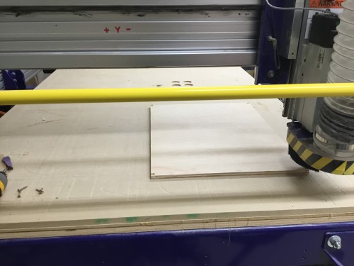
I added tolerances to practically every corner. Once I was done, I felt pretty confident that I did not need to make a laser cut version due to the new skill that Mr. Rudolph had taught me, so I went straight into making my toolpaths. I used Aspire to make them. I ensured that I corrected all of the mistakes that I made during CNC week. This time, I double checked that offset was turned off and that my tool would be basing it’s measurements off of the bottom of the board for the whole entire cut. I also paid attention to have the slots be cut from the inside out and the outline profile paths be cut from the outside. I then added my tabs and saved the file to cut.
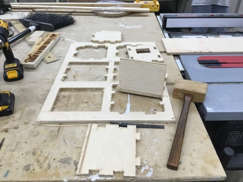
The plank of wood that I selected was a really big, so I got Mr. Rudolph‘s help to cut the board to be 18x24. He taught me how to use the table saw safely and get the straightest cut possible. I had to press the wood into the bar on the left and walk forward while pushing the board. This way, the cut would come out straight and not janky. I also needed his help to drill the board into the bed because I couldn’t reach far enough, haha. He then also helped me zero the Z axis and jog it to where we had placed the board. Once everything was set up, I first did a 3D offset and watched it in full to verify that everything would go as planned. No issues were apparent, so I started up the spindle and cut for real immediately after. By far, this was the best cut that I’d ever done. It went smoothily which I believe was due to the extra checks that I did. Now, I just needed to get rid of the tabs and sand the edges. I used a chisel to detach the tabs, and I manually sanded the edges apart from the flat sides. For those, I used a woodworking sanding machine for a flatter edge.
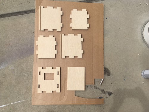
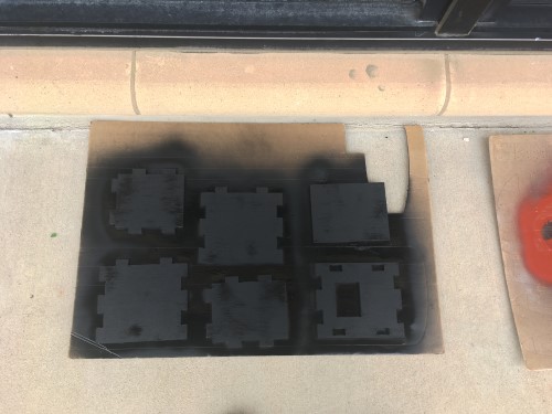
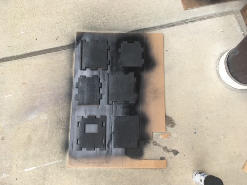
As I was tidying up the last couple of edges on the pieces, I began to think about how I would decorate them. Eventually, I decided on a space themed decor for obvious reasons. I spray painted them black on both sides and once they were dry, I took a paint brush and sprinkled their outer faces with white to emulate stars. I’m happy with the way they turned out! I did mess up a few times, but I simply covered the errors with black paint and started over.
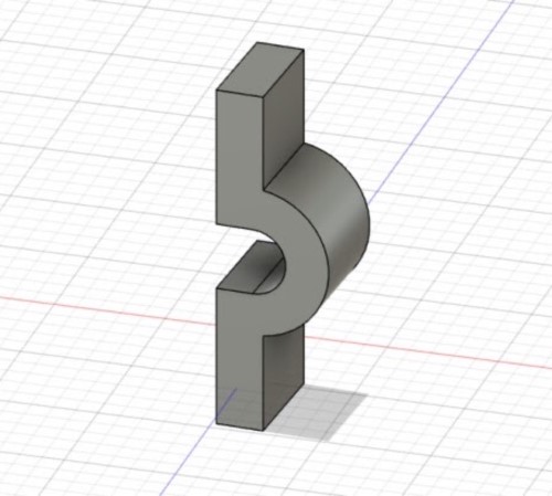
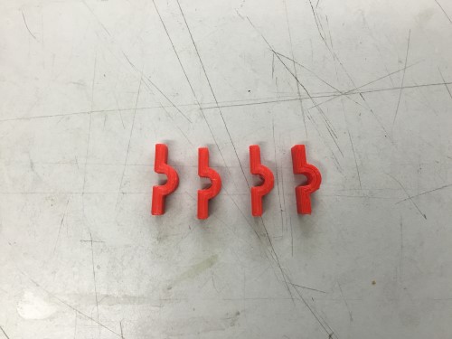
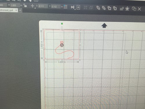
3D Printing
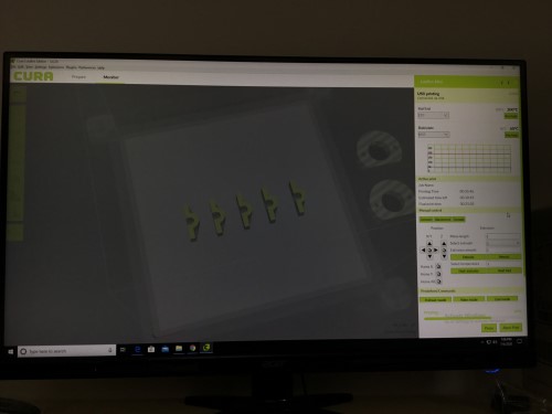
For my 3D printed portion of the project, I created hooks for the wires to place on the walls of the box. In Fusion, I used the line and arc tools. I saved it as a .SVG and opened the file in Cura. From there, I made sure that the heat settings were correct for the printer and copied the design 5 times. The print was over in >20mins which was nice. Unfortunately, the middle print did not stick to the best and got all tangled, but I really didn’t care because 4 would work as well. This was overall a very quick process and only took me around 45 mins in total.
Vinyl Cutting
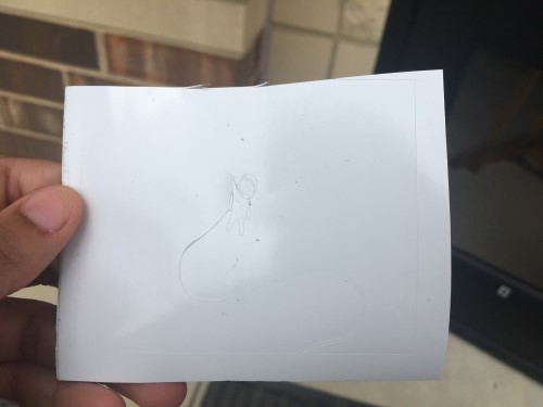
I made a sticker of an astronaut just to add some extra pazazz to the box. At first, I was planning on rastering/engraving the design onto it, but Elaine suggested that I make a sticker instead because then I wouldn’t have to paint in the astronaut after the fact. I selected this image that I found online:

and then in Corel, I made a bitmap trace and saved it as an .SVG. After importing the file into Sillhoutte, I loaded up the machine with the white sticker mat I had chosen. It came out nice, but I noticed that the wire connected to the astronaut’s suit was a bit thin. I took an exacto knife and cut it to be a bit larger.
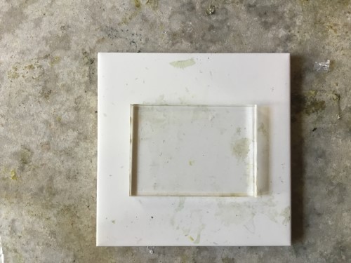
Laser Cutting
Finally, when constructing everything, I noticed that the display would be exposed if I just left it as is, so I quickly made some measurements with a caliber and cut out a screen using 1/8” acrylic. Unfortunately, because I had rushed, I neglected to notice that the caliber was not zeroed, so I did not have the right measurements. Each were 0.8 off. The screen ended up being too small. I zereoed the caliber, remeasured, and cut the screen again, and it fit perfectly! Because it fit so tightly, I did not need to add an extra adhesive for it.
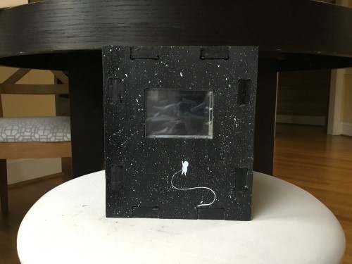
Finished Product
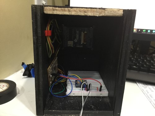
Once I constructed the box together, I assembled the electronics inside neatly to give it a polished feel.
I took a video within a three hour time frame to show some shifts in the constellations because it only moves significantly every hour. Here is my final presentation video which is also linked at the beginning of this page. The time lapse is at the end.
And that was it!
My files: