Charlotte Latin 2020 Week 17 Group Assignment
Mechanical and Machine Design
Slide
Members
Brainstorming Ideas
We began by looking at past projects that people made for this week. Some ideas we were interested in including:
We decided that we liked the concept of a pancake maker, but wanted to alter it to be a cupcake pan filler. The machine we would make would fill a cupcake pan with the correct amount of cupcake batter.
Materials
| Material | Amount |
|---|---|
| Cupcake Dispenser | 1 |
| Stepper Motors | 3 |
| Servo | 1 |
| Guide Rods | 6 |
| Pulleys | 6 |
| 6mm wide Belts | - |
| Arduino Uno | 1 |
| CNC Motor Shield | 1 |
| Zip Ties | 10 |
| Cable Wrap | - |
Components
- A dispenser with the cupcake mix and a mechanism to “release” the cupcake batter from the bag when the dipenser is over the cupcake molds.
- Two-axis movement machine that goes over the cupcake tray
- We decided to use a different project that we had been considering as the inspiration for the two-axis movement component
- The pancake maker used the same two-axis movement component, but this project displayed it better.
Making the 2-axis movement - Elaine & Alexandra
For this portion of the project, we sketched out what the gantry system would look like.

Afterwards, we thought that using a CoreXY gantry system would be better suited towards using GRBL, so we briefly changed courses. We re-sketched out what the gantry would look like and began designing the platform.


Upon realizing that GRBL did not require using the CoreXY system and that it would be more complicated if we used the CoreXY design, we switched back to our original idea and began designing. For this group project, our team split up to work on the different components of the project.
When it came to designing the parts, we decided to use Fusion360. The different pieces we needed included:
- brackets for the ends of the rails
- gantries for the Y axis
We decided that we would use the same general design for the brackets as the gantries, but the gantries would be additionally screwed into a platform. Here are the different bodies:
Idler Bracket: The bracket opposite the stepper motor

Stepper Motor Bracket: The bracket with the stepper motor

Platform


The individual pieces were designed while we were not at the lab, so everything was parametric so that they values could be changed once getting the correct dimensions from the materials in the lab. Here are all the parameters used:

The next step was creating a simulation of what our general design would look like. We implemented all the parts that had been designed in one sketch, as well as simulated the design of the cupcake pan. This is what it looked like:

Once we got back into the lab, we could begin 3D printing the parts. We started off by printing two motor brackets. Because these were long prints, we had them print overnight. When we got back into the lab the next day, we realized that the 3D prints had somehow shifted slightly while being printed. We did not want to waste PLA and more time, so we used the table saw to cut off the part that had shifted and used the remainder of the pieces.


Though these two prints would not be connected, as they were each a motor piece, we wanted to put the rails in to see how they fit together. Here is what that looked like:

We then continued to print the idler brackets and the platforms. We actually messed up printing the platforms several times, unfortunately. The first time, we left the print running overnight but did not check to see if we had enough PLA. We came back the next morning and saw that the PLA had run out and we needed to restart the print. The next time, we started the print and there was a tangle in the PLA, inhibiting it from being extruded. You can see that the job was halfway done before we had to restart the print again:

Finally, we were successful in printing the first two platforms. Here is a picture of the X axes rails with the brackets and platforms:


The next step was printing the parts for the Y axis. We needed the gantries: one more idler and motor bracket, along with another platform. Once those parts were printed, we were able to continue assembling the machine.
To download all the files for the 3D printed parts, click here.
Making the Dispenser Mechanism - Harri, Vincent, & William
One of the main components that we needed to design was the cupcake batter release mechanism. The batter is going to be stored in this dispenser, which works by pulling the handle in order to release the batter. Therefore, we needed to create a mechanism that could sturdily support the dispenser and actuate the handle so that the batter could be dropped into the molds. The idea that we came up with was that there would be a curved 3D printed mount that would clamp around the dispenser and house a servo motor with a knob that would actuate the lever to release the batter.
Mount - Vincent
We created a prototype CAD mock-up of the mounting mechanism. The idea is that the two bolts will pinch the dispenser from the side and the mount will be attached to a vertical surface of some sort.


With the rough mount figured out, it was time to refine the models and integrate them into the gantry designs. To start, we parameterized the models so that any dimensional changes that we needed could easily be done.

Next, we imported the gantry designs to design an adapter between the dispenser mount and the gantry plates. However, the gantry designs were left as bodies instead of components, so nothing had joints. This made it hard to design and visualize the integration of components, so we converted the gantry designs into components and joined the components together with appropriate joints to reform the original assembly. The joints allowed the plates to slide, so I could emulate the real world movements of the gantry.


With the gantry assembly created, we created an adapter between the mounting holes of the dispenser mount and the mounting holes of the gantry plates.


However, the adapter proved to be too shallow because the team decided that the adapter was to be placed on the back of the plate and thus the mount was too recessed into the plate. A revision was made to increase the height of the adapter to fit the handle of the dispenser.


Now, we 3D printed the CAD models. First, we attempted multiple prints of the mount as the nut sometimes couldn’t fit into the slots due to tolerances. In addition, we downsized the diameter, height, and thickness to reduce material cost and print time. After the fourth attempt, we fabricated a mount that was capable of fitting the nuts and being threaded with bolts.

Next, we 3D printed the adapter. The adapter fit perfectly with the mount and we could attach the two parts together.

The dispenser fit perfectly into the mount and the adapter.


Release Mechanism - Harry & William
For the group project, Harri Seto and I worked collaboratively on the dispenser mekanism and how we are going to squeeze the handle of the cupcake batter dispenser. However, before I started working on the mekanism, Harri ran into a few problems getting a smaller stepper motor to push the cupcake dispenser handle backwards. It seemed there was too much resistance from the handle of the cupcake dispenser for the stepper motor to handle. Thus, instead we used a HS-475HB servo.
With tetrix frames, William created a temporary arm to test whether even this servo had enough torque to be able to push the cupcake batter dispenser. However, even this servo lacked in power and was unable to even inch the handle backwards.
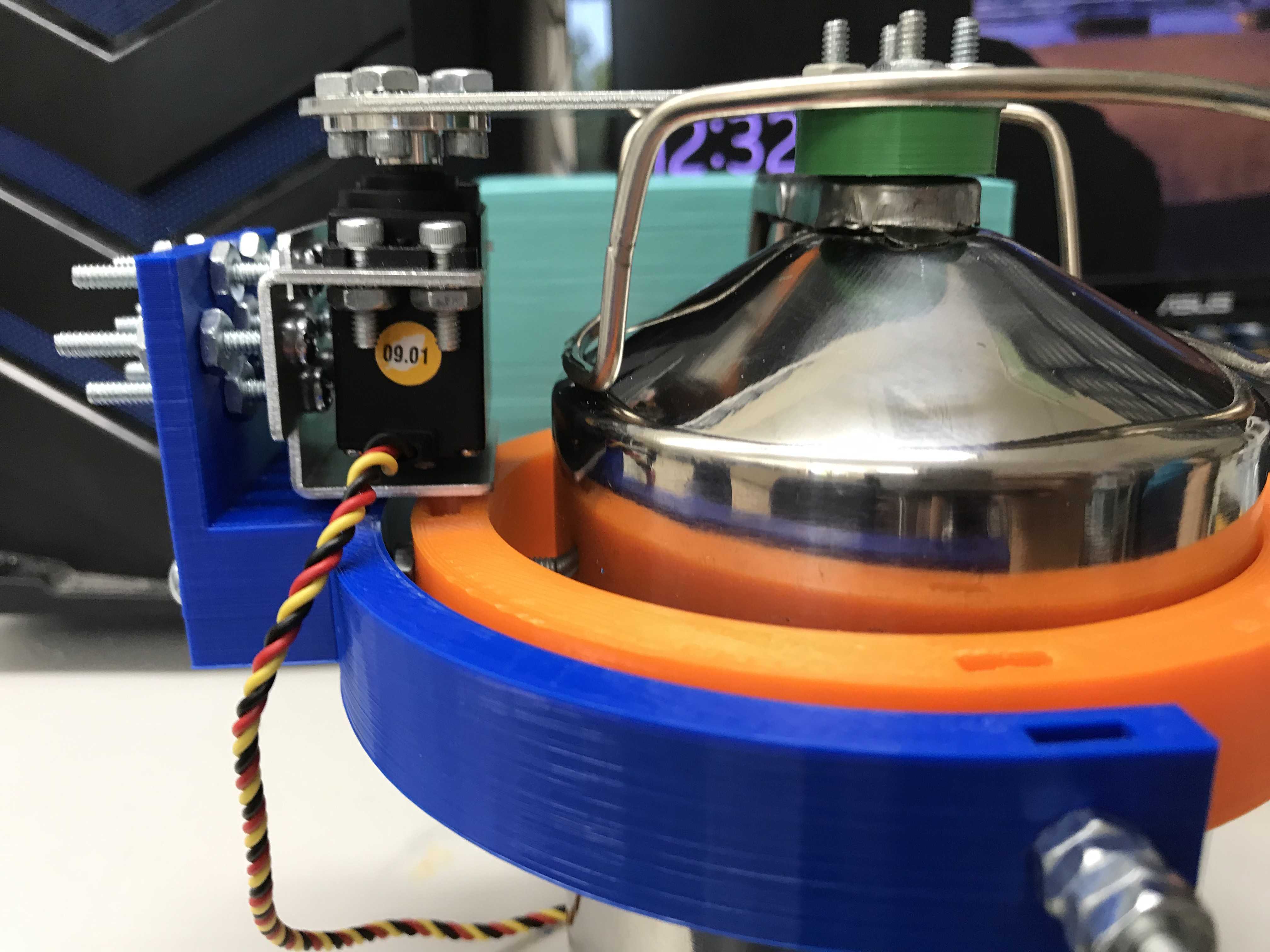
Without any servo or stepper motors powerful enough to push back the cupcake dispenser, an alternative solution was developed where the handle of the dispenser would be ziptied open and a servo with an arm would block the bottom of the dispenser. To use this design, it was also mandatory that we create a mount dedicated for the servo. Thus, Harri and William created a CAD of a servo mount that would build off the already existing screws of the dispenser mount that Vincent Zhou created.
In addition to the servo mount, here is the piece that we will attach on the servo arm to block the nozzle of the cupcake dispenser:
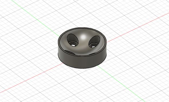
Here it is 3D printed. While PLA is not food safe, during actual use it will be covered in food safe plastic wrap or be printed out of food safe PLA to ensure there is no contamination in the batter.
The piece felt decently well and here is the contraption assembled with the nozzle:
However, there was lots of batter overflowing from the nozzle meaning that the piece failed.
Thus instead, Vincent suggested that the piece instead simply be flat on the top plane as there was no need for slopes. Here is the CAD:
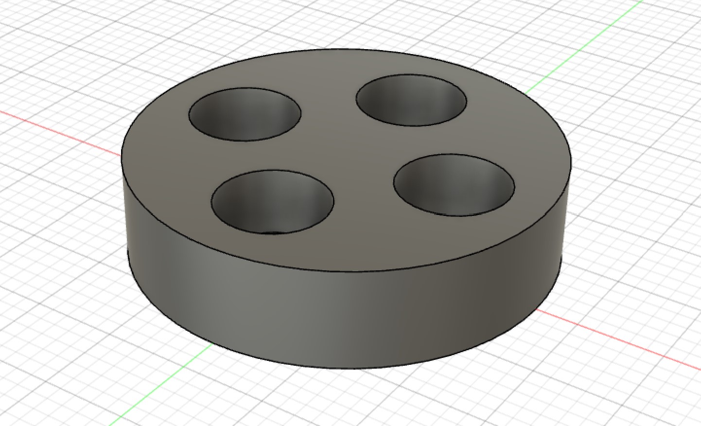
This is the finished product with the replaced pieces and the cupcake batter dispenser almost no spillage now:
Stepper Motors & G-Code - Sydney & Sophia
GRBL is a very powerful software, but we had two main problems trying to interface it with our gantry system.
Firstly, our group’s gantry has two x motors moving in the exact same way. We had to figure out how to clone the movement of one of our X-axis motors.
Secondly, we do not have a “spindle” tool, which will cut material. Instead we have another motor, which only needs to turn slightly to enable a release mechanism for the batter.
We thought we had to rewrite GRBL code to do these two things, but we quickly realized there were much simpler solutions
Cloning the X-axis - Sydney & Sophia
This video showed me that we could connect jumpers labelled “X” on the side of the shield, and connect another motor to the A Axis, and the movement would be cloned.
This seemed simple enough, but when testing it out, we found that the A axis motor would spin very quickly at the beginning, buzz as the original X axis motor turned, then spin very quickly.
I consulted Sydney, and after troubleshooting for a while, we sought advice from former Fabacademy student and node instructor Mr. Rudolph. He pulled up the motor drivers from the shield, and pointed out that there were pins under all of them. The pins were connected by jumpers on every axis, except the A axis (which was connected to a motor that was turning in an irregular way). The controlled rates of microstepping. Different combinations of the jumpers would result in reduced stepper seeds. One step is the norm, however, it actually takes a lot for a stepper motor to turn one whole step, and the stepper motor on the A axis was simply being told to turn so quickly that it couldn’t keep up, and turned in the irregular fashion we observed. The jumpers were in a 2x3 grid, and we referenced this chart to see which combinations led to which microstepping speed:

M0 M1 and M2 are the possible connections the pins can make. We chose to make all the motors operate at a uniform 16th step, for now.
Release Mechanism - Sydney & Sophia
Originally, our plan was to use a servo motor and attach it to the pins on the end of the shield, which are configured specifically for Servos’. However, Dr. Harris recommended we use another stepper motor, because then we can use one of the axes on the shield (the setup/commands will be uniform with the other stepper motors, instead of having a whole new servo setup/set of commands to deal with). He also recommended a very specific type of stepper motor (28BYJ-48) we had in the lab, which is very strong and would be compatible with the release mechanism, being designed by our peers Vincent Zhou and Harri Seto.
The one difficulty with this motor was that it was a unipolar motor, not a bipolar motor, which this shield was configured to work with. However, Unipolar motors and Bipolar motors utilize different connections between coils, however, the coils themselves are technically the same. So, we were able to change the wires of the unipolar coils, to make the motor function like a bipolar motor.
We found this YouTube video which explains how to do this. This website gave us a diagram of the colors and coil numbers and also provided the datasheet for the stepper motor.
Unipolar Motor wiring:

Bipolar Motor Wiring:

Bipolar to CNC shield:

(4 wire not 6 wire configuration)
Using these diagrams, we were able to figure out which coils were which on unipolar vs bipolar motors. As long as the wires line up (coils 1, 2, 3, 4 or coils 4, 3, 2, 1) when they are plugged into the shield, the motor will function. If the motor spins in the wrong direction, simply flip the order of the pins.
| # | Unipolar Coil | Bipolar Coil |
|---|---|---|
| 1 | Blue | Yellow |
| 2 | Pink | Green |
| 3 | Yellow | Red |
| 4 | Orange | Blue |
GRBL controlled by GRBL commands - Sophia
GRBL is only the protocol that the arduino runs. GRBL has a set of commands which will communicate G-code to the motors. This is the simplest way to control the machine, and it gives the machine free mobility. If you look at a normal milling machine there is usually a command functionality that allows you to move the tool freely. However, there is also a component that allows you to load G-code in some way. The G-code send the tool in complex toolpaths, and is capable of making all the beautiful creation we’ve seen come out of CNC machines, milling machines, 3d printers (an additive version of this), etc. Right now, we will focus on simple commands.
Fortunately, the Arduino IDE has a built in Serial Monitor, which can be used to send the commands. Otherwise, we would have to connect some terminal or other program to our Arduino board.
The only steps needed to do this are
- Download GRBL
- Determine the settings for your specific machine
- Send commands
This instructables tutorial goes through the steps to download GRBL-master as a .zip, extract it, and load the “grbl” subfolder into the Arduino IDE as a library. Once you do this, you simple open the code through examples, flash the code, and then GRBL is on your arduino.
Once you do this, you can open the Serial Monitor to start communicating with GRBL. One you set the Baud rate to 115200, the last line on the serial monitor below will appear:

We used the GRBL wiki as a reference for commands. We also used this site to specifically learn how to move one axis at a time. The most basic commands:
- X movement command- “G0Xn”
- Y movement command- “G0Yn
- Z movement command- “G0Zn”
“N” is the variable that can be subbed in for any number of steps.
We did not need to do “G0An” because the A axis was configured to clone the X axis, and therefore would move whenever the command “G0Xn” was used.
At this point, we configured the settings for our machine. Firstly, we needed to change the steps per mm of our motors. GRBL takes inputs in mm, but the motors use a unit called “stepps.” To get an accurate distance travelled, GRBL needs to know how many steps correspond with how many mm for our specific motors. The integrity of our cupcake gantry depends on it. We used the Nema 17 motors for the gantry, and used this calculator for our measurements.
Most of the information we needed was on the component’s datasheet The microstepping value was 1/16th, because this is what we had set it as earlier by connecting the M0 M1 and M2 pins.

Nema Motors have 80 steps per 1 mm. The Nema motors were controlling the X and Y axis. To change the default steps/mm in GRBL for the X axis, you type “$100=80.00”. To change it for the Y axis, you type “$101=80.00.”

The Z axis is controlling the [28byj-48], and that measurement does not control either of the axis we are using, so it doesn’t need to be very precise. It simply needs to turn approximately 90 degrees, then turn back to 0 a few moments later.
We did not change any of the other settings. We considered changing acceleration, but the defaults were all pretty reasonable so we left them alone. When we integrate the motors into the gantry, we may change this, because we do not want the gantry to move too slowly/too quickly.

GRBL controleld by G-Code - Sydney
There are a couple of different ways to write G-code. Since it is such a complex set of instructions, usually programs like Fusion 360
After a discussion with our teacher, he told us that it would be best and very possible to write our own g-code from scratch which would probably have around only 50 lines. We wanted to create a rough draft of the code, leaving out the details, just to have an outline that we could fill in and edit later. BecauseWeam relatively unfamiliar with the language,Wetook some time to read through some info about the language. First and foremost,Weneeded to know how to start the code. This write up from Autodesk was very informative on getting started and the necessary basics of Gcode. We learned that g-code stands for “geometric code,” and follows some variation of the alpha numeric pattern: N## (line number) G## (Motion) X## (Horizontal Position) Y## (Vertical Position) Z## (Depth) F## (Feed Rate) S## (Spindle Speed) T## (Tool Selection) M## (Misc functions) There’s alsoWeand J which are the incremental center of an arc and R which is the radius of an arc. G defines the motion and function, XYZ declare the position, F and/or S set a value, T selects an item, and M switches things on and off (ex: coolant, spindle, etc.).
According to Autodesk, g-code tells the machine to do one of these three basic motions and how to do it:
- Rapid move: a linear move to an XYZ position as fast as possible
- Feed move: a linear move to an XYZ position at a defined feed rate
- Circular move: a circular move at a defined feed rate
I just wanted to get started with messing around with g-code, so we used the website-based program, Chilipeppr to do some hands on learning.
First, we had to set up the serial port JSON server. This honestly took me a bit to figure out because in the video that we were using, the site sent them directly to the set up of the port whereas now, it sends you to JSFiddle. We simply ran the code, and the same screen as in the video showed up in JSFiddle.
Why this is important: We know exactly what our cupcake system requires. It would be much easier to upload all that code at once, instead of typing in codes manually. Also, understanding how to send G-code opens the potential to use the gantry as a complex machine like a CNC machine or a milling machine of some kind.
Using Powershell with GRBL
Powershell can access the serial monitor that Arduino opened for GRBL through a simple streaming program inside of the GRBL folder we downloaded to out computer. Navigate to **Grbl-Matser -> doc -> Script ** and open Simple_Stream.py. Python must already be installed on your computer. The computer we used already had python installed, but we would have used [this](https://www.codecademy.com/articles/install-python) tutorial if it was not already installed.
The following file should appear:
#!/usr/bin/env python

Simple g-code streaming script for grbl

Provided as an illustration of the basic communication interface
for grbl. When grbl has finished parsing the g-code block, it will
return an 'ok' or 'error' response. When the planner buffer is full,
grbl will not send a response until the planner buffer clears space.

G02/03 arcs are special exceptions, where they inject short line
segments directly into the planner. So there may not be a response
from grbl for the duration of the arc.

---------------------
```
The MIT License (MIT)

Copyright (c) 2012 Sungeun K. Jeon

Permission is hereby granted, free of charge, to any person obtaining a copy
of this software and associated documentation files (the "Software"), to deal
in the Software without restriction, including without limitation the rights
to use, copy, modify, merge, publish, distribute, sublicense, and/or sell
copies of the Software, and to permit persons to whom the Software is
furnished to do so, subject to the following conditions:

The above copyright notice and this permission notice shall be included in
all copies or substantial portions of the Software.

THE SOFTWARE IS PROVIDED "AS IS", WITHOUT WARRANTY OF ANY KIND, EXPRESS OR
IMPLIED, INCLUDING BUT NOT LIMITED TO THE WARRANTIES OF MERCHANTABILITY,
FITNESS FOR A PARTICULAR PURPOSE AND NONINFRINGEMENT. IN NO EVENT SHALL THE
AUTHORS OR COPYRIGHT HOLDERS BE LIABLE FOR ANY CLAIM, DAMAGES OR OTHER
LIABILITY, WHETHER IN AN ACTION OF CONTRACT, TORT OR OTHERWISE, ARISING FROM,
OUT OF OR IN CONNECTION WITH THE SOFTWARE OR THE USE OR OTHER DEALINGS IN
THE SOFTWARE.
---------------------
"""

import serial
import time

# Open grbl serial port
s = serial.Serial('COM8',115200)

# Open g-code file
f = open('cupcake.gcode','r');

# Wake up grbl
s.write(str.encode("\r\n\r\n"))
time.sleep(2)   # Wait for grbl to initialize
s.flushInput()  # Flush startup text in serial input

# Stream g-code to grbl
for line in f:
    l = line.strip() # Strip all EOL characters for consistency
    print('Sending: ' + l,)
    s.write(str.encode(l + '\n')) # Send g-code block to grbl
    grbl_out = s.readline() # Wait for grbl response with carriage return


# Wait here until grbl is finished to close serial port and file.
raw_input("  Press  to exit and disable grbl.")

# Close file and serial port
f.close()
s.close()
We changed the serial port to ‘COM8’ and the filename of the gcode file to match our gcode file. The gcode file must be in the same directory as simple_stream.py.
Before running the file, run pip install pyserial and pip install pytime on powershell. These are two libraries that the simple_stream.py code references.
Then, simply cd into the directory where simple_stream.py is being stored, and and type in python simple_stream.py

When we successfully uploaded it, it printed the commands that were being sent through the gcode.

The plan was to move the machine to the left corner cupcake hole by jogging the machine with the serial monitor on arduino IDE(we could have used powershell but wanted to keep it simple), then stream this handwritten code. We believe more complicated code, but we did not test it out.
G0Y84.01
G0Z100
G0Z-100
G0Y84.01
G0Z100
G0Z-100
G0Y84.01
G0Z100
G0Z-100
G0X85.04
G0Y-84.01
G0Z100
G0Z-100
G0Y-84.01
G0Z100
G0Z-100
G0Y-84.01
G0Z100
G0Z-100
G0X85.04
G0Y84.01
G0Z100
G0Z-100
G0Y84.01
G0Z100
G0Z-100
G0Y84.01
G0Z100
G0Z-100
The positions are relative.
Controls - William
One of the reasons that Harri had tried to use the stepper motor previously, was due to the CNC shield not having support for a servo motor. However, with the dispenser mechanism using a stepper motor now, something with the CNC shield had to be done now. Using a guide on how control a servo motor with a GRBL CNC shield, William was able to get the servo integrated into the shield. This method will utilize a modified GRBL firmware called MIGRBL to contorl a stepper motor in replacement of a spindle on a CNC machine.
You need to download the following two items: MIGRBL Firmware MIGRBL inkscape extension
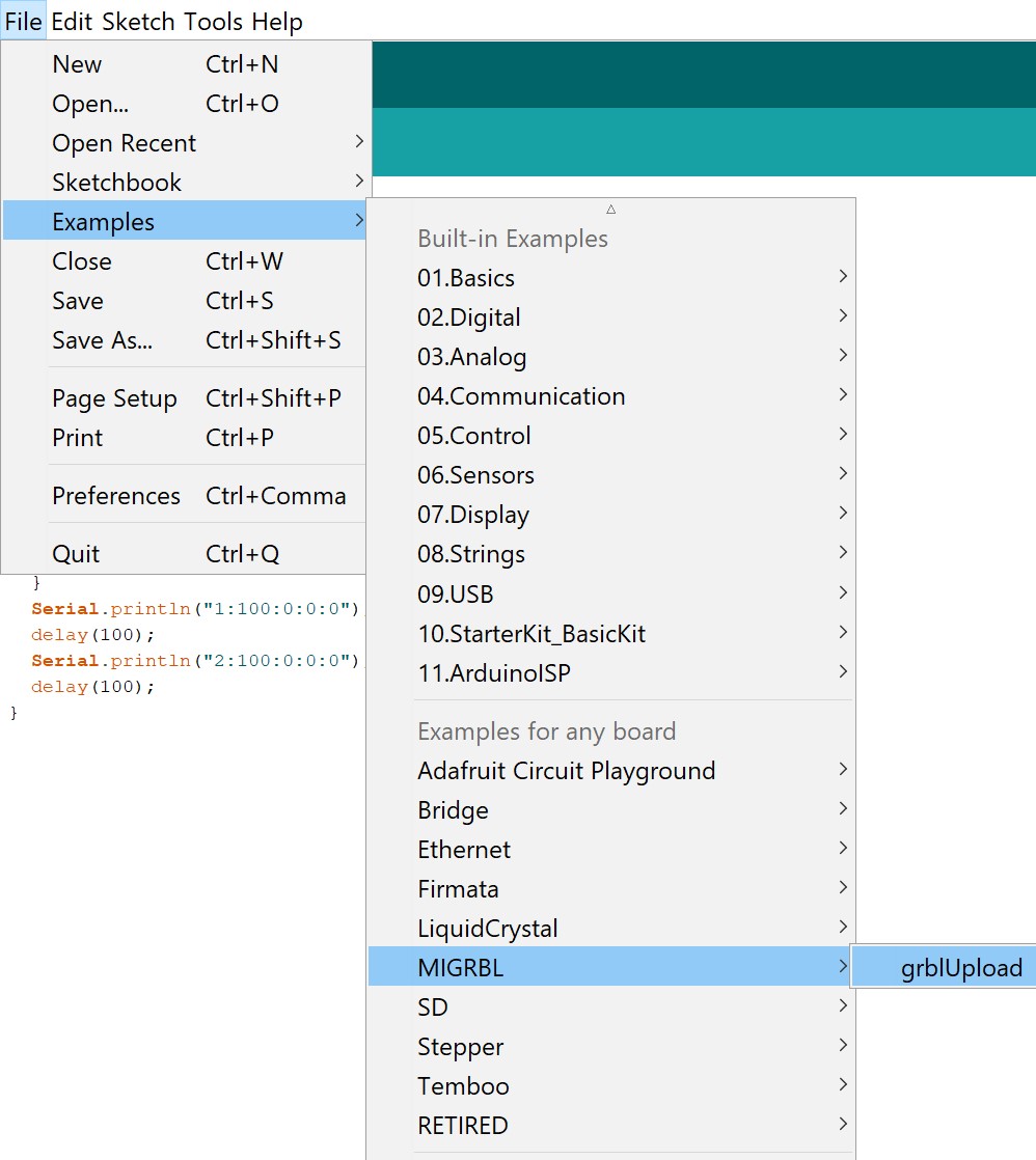
MIGRBL is the exact same as GRBL, so unzip this folder and import this library as you would with regular GRBL. Now in the Arduino IDE under examples>MIGRBL click the only example they have “grblUpload” and upload this code to your Arduino Uno. Remember that when uploading code to the Arduino Uno, it can not be connected to the CNC shield or you will get a programmer error.
Now, the connections for the servo motor is a little different. Here is a little diagram that shows you how to connect a servo to the GRBL CNC shield.
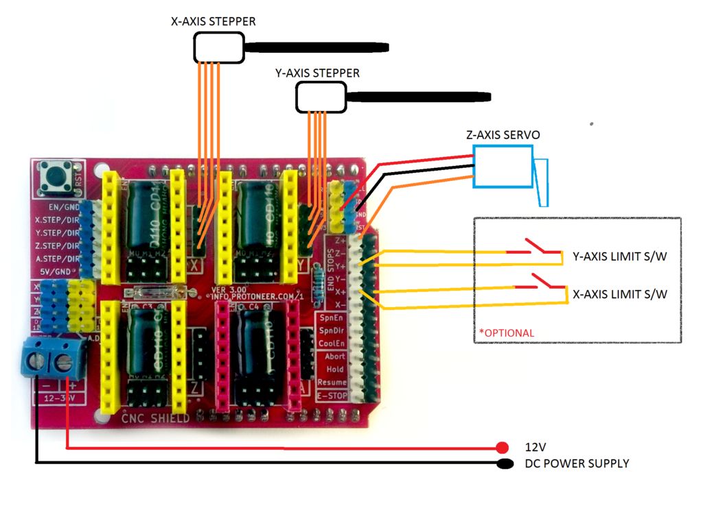
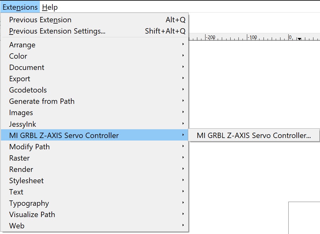
Connect 5V and Ground to the corresponding pins on the GRBL CNC sheidl and then connect signal to the D11 pin or the Z+ End Stop Pin. To use MIGRBL, you will need the MIGRBL extension made for Inkscape. Extract the previously downloaded folder and copy all the files inside into your extensions folder for Inkscape. Now when you restart Inkscape, a new extension should pop up called MI GRBL Z-AXIS Servo Controller.
From the guide, here are the steps for generating G-code:
- Open the Inkscape software
- Go to the file>Document properties
- Set the units to mm
- Set width and height of your plotting area and close the tab
- Now draw the design or drag and drop the image of your choice (If you have drawn something itself in inkscape skip to step 12)
- Now select the image and go to the path>trace bitmap
- Click ok and close the tab
- Now hold click on the image and drag the mouse
- A black and white image will separate from the original image
- Now delete the original image
- Drag the black and white image in center of the frame
- Again goto path>object to path
- Now go to Extensions tab and select MI GRBL Z-Axis servo controller
- Change the values if needed
- Click on apply to generate the G-code
- Default location where you canfind the generated G code is C:/Users/Public
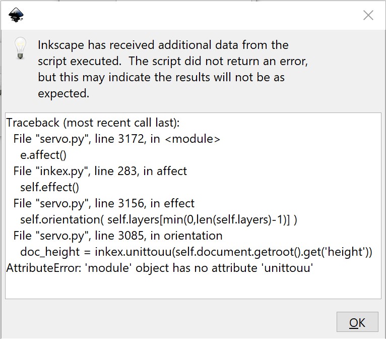
Searching this problem up, a blog traced the problem back to one line in the code that was outdated and broke due to an Inkscape change. The error in the code is on line 3080 of servo.py and you need to change
doc_height = inkex.unittouu(self.document.getroot().get('height'))doc_height = self.unittouu(self.document.getroot().xpath('@height', namespaces=inkex.NSS)[0])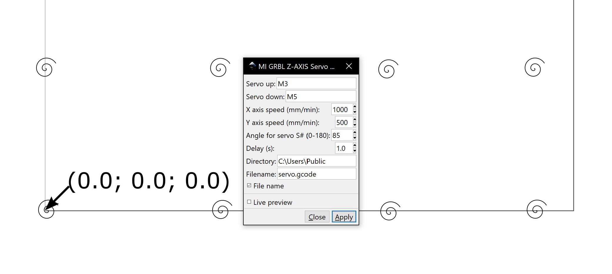
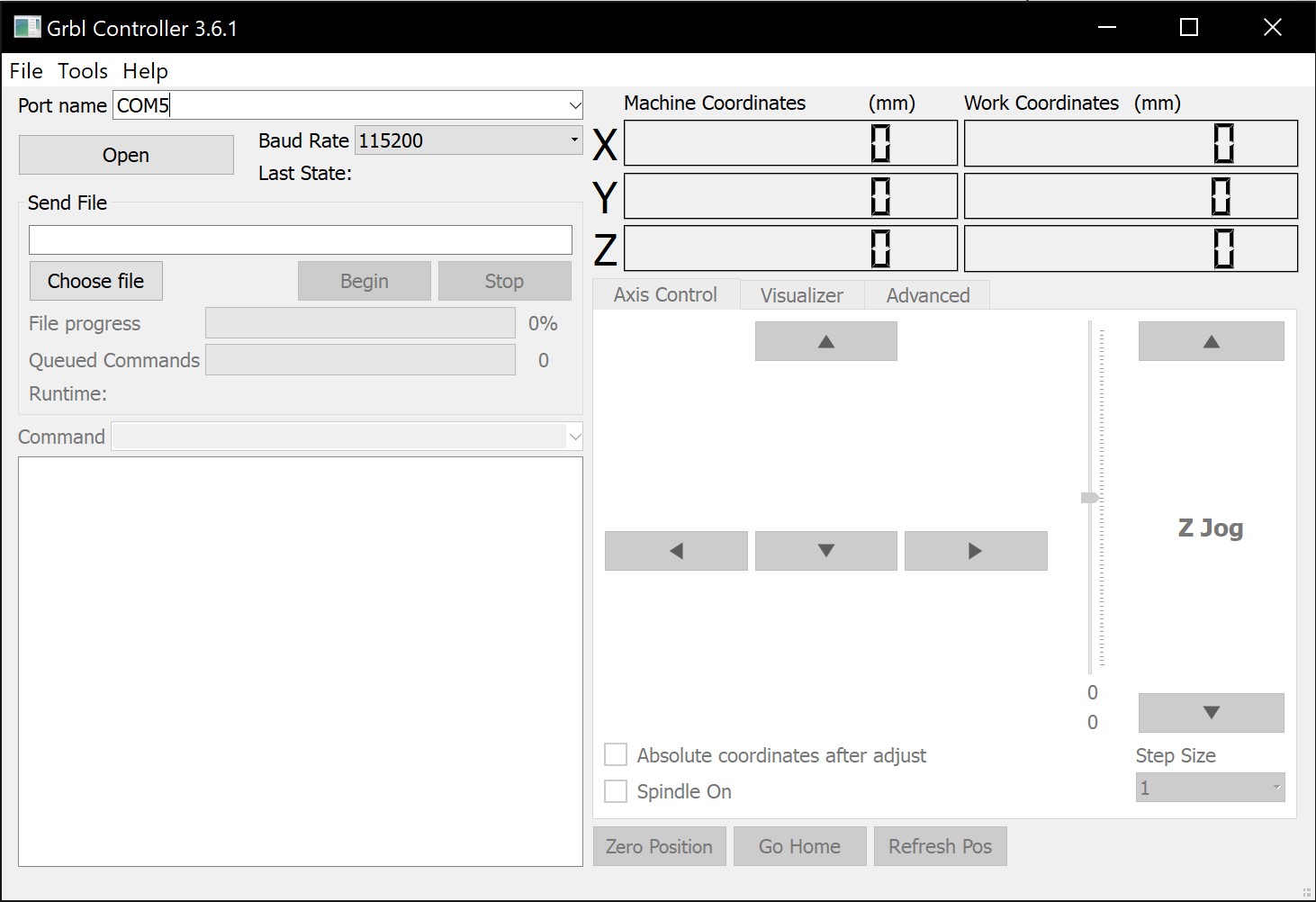
Now once this .gcode file is ready, I used a simple grbl controller to read the .gcode file and send commands over serial. This program was very simple to use and we were easily able to get it to work. Simply connect to the correct COM port in the top left corner, and then load up a .gcode file just below that. Be aware that pressing the Stop button doesn’t instantly stop the machine as there could still be some gcode being executed by your CNC shield before you stopped the grbl controller.
Assembly
Once we had all the pieces printed and code working, we began assembling the machine.


