This week's aim was to develop a mechanical design based on computer based numerical controlling.
It was decided to build a machine similar to a normal Pantograph. The machine has 2 degrees of freedom. The rotational movement of the stepper is converted to the desired translational displacements by means of interconnected straight link mechanism connected in parallelogram geometry.
Project Management
Since there were only 3 students in the Lab, it was pretty easy to divide the work between ourselves the whole task of machine building.
The task planning was done and the division of work is attached here below.
Project Management Details here
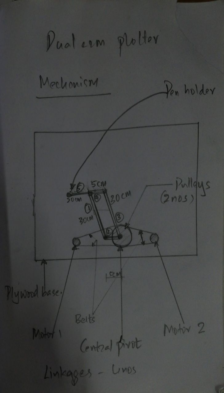
Mechanism
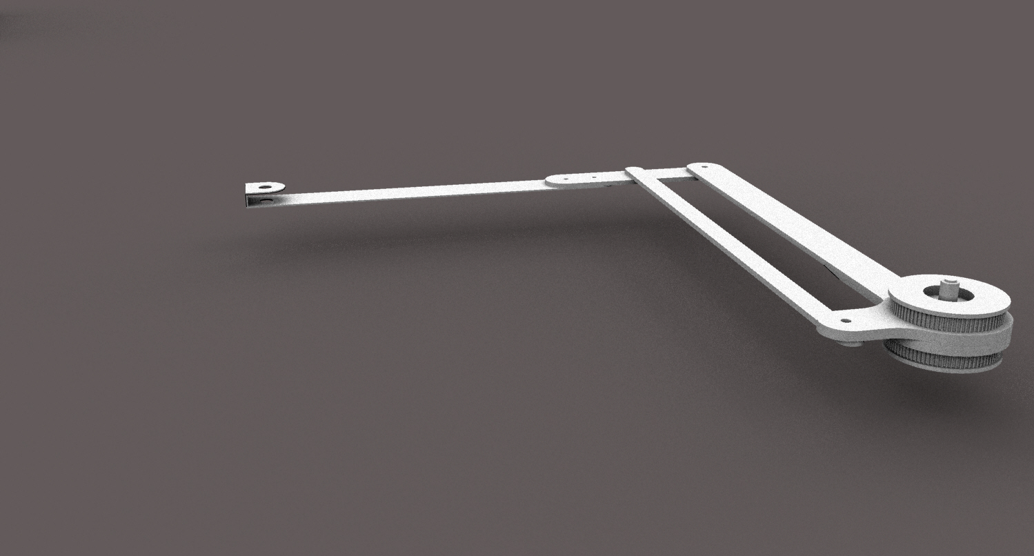
The system has 3 connected linked arms that are free to rotate at joints. The linkages no 4 and 5 are rigidly connected as one piece. These two together form the elbow.These linkages are made of weightless material that it operates in cantilever position from the central shaft during operation. The pen holder is placed at the tip of the link 5 (Seen in the picture below). Linkages no 3 is connected directly to the pulley erected in the central shaft. The main rotation of the arm is controlled by linkage 3. Linkage no 1 is connected at an offset to the pulley using a small linkage no.2(Later this was directly incorporated with the pulley itself).Linkage no 1 controls the rotation of the elbow linkages 4 and 5 indirectly. These connected linkages behave in such a way that at any point a parallelogram in closed connection is form by them. The desired position of the pentip can be acheived by calculated rotations of the connected linkages no 3 and 1.
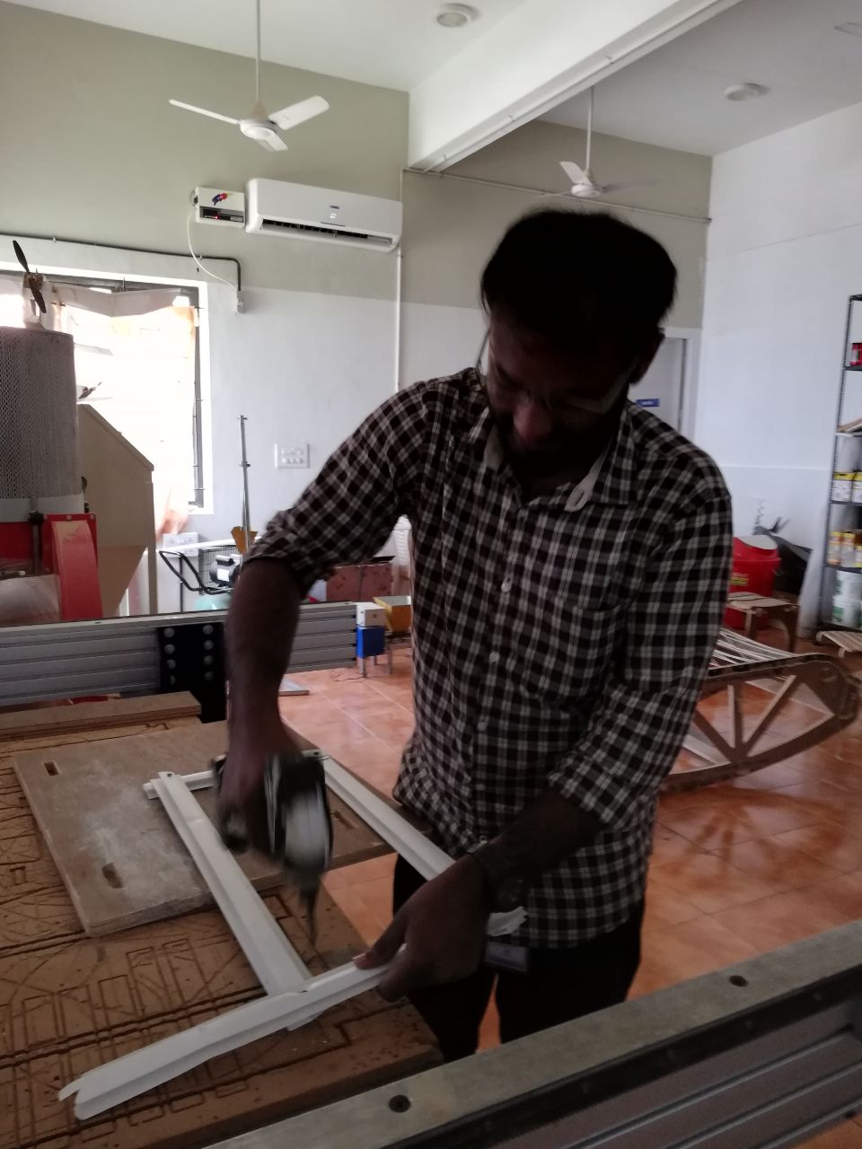
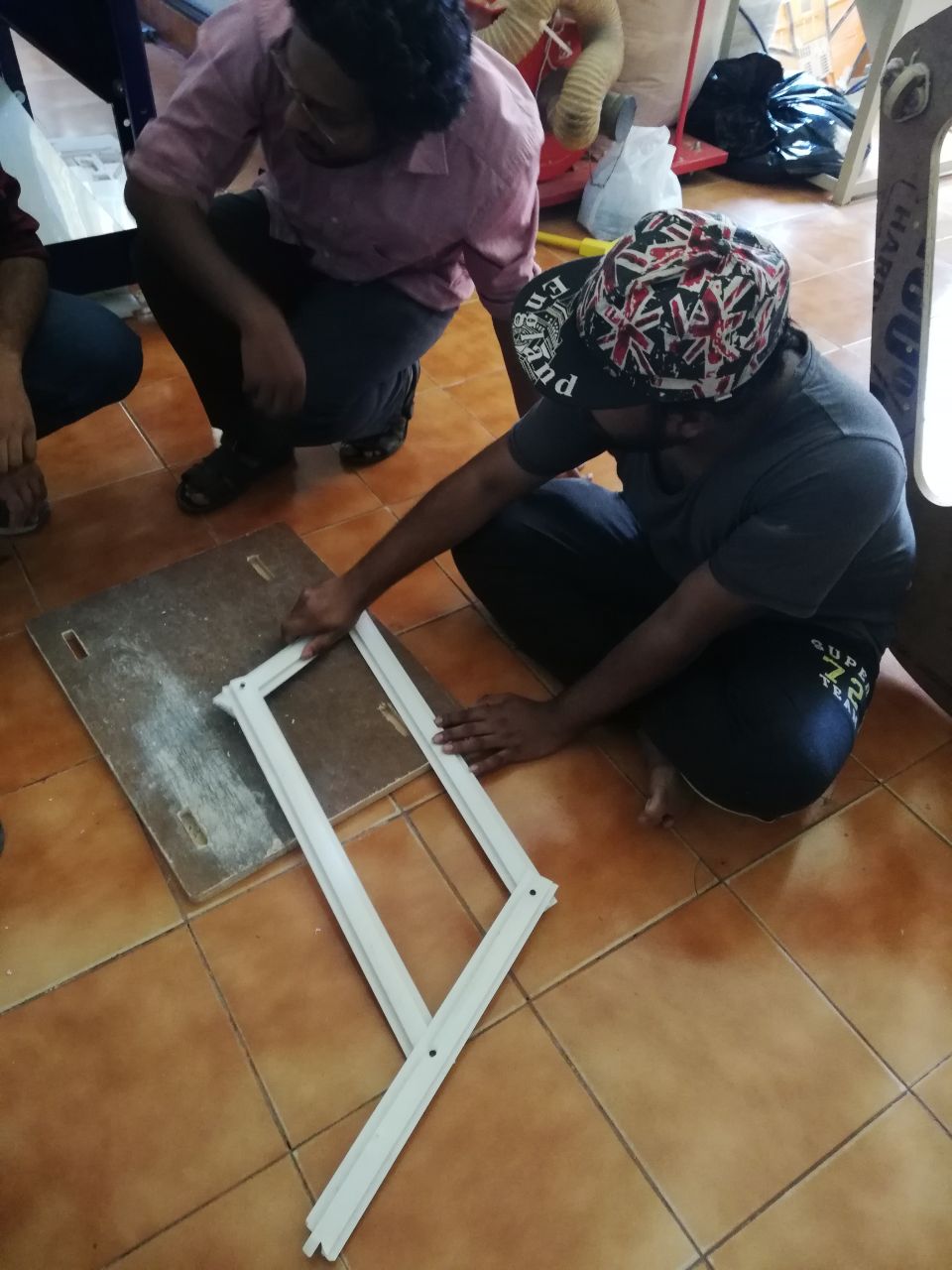
For testing the mechanism we cut the scaled sizes of the plotting arm in pvc and fixed it to the plywood base to simulate the plotter arms motions.
The pvc panels are screwed at the joints to simulate hinges at the joints.
The arms are pivoted at the base and checked for free motion of the arms to understand the behaviour of the lnkages.
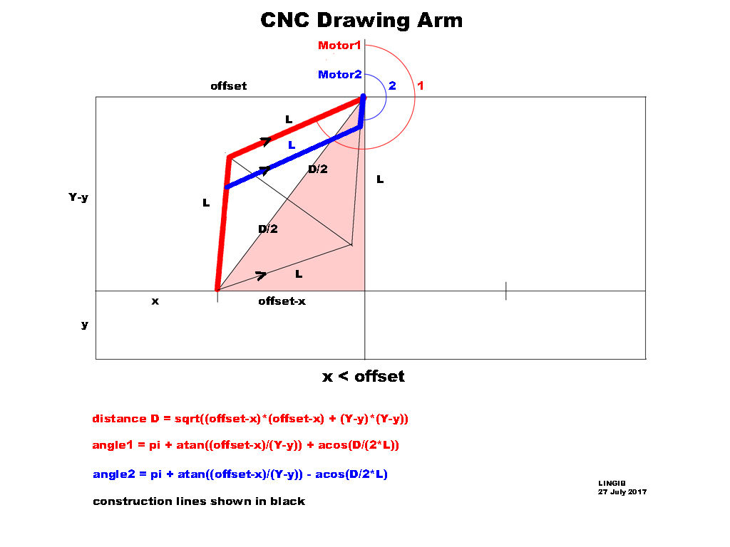
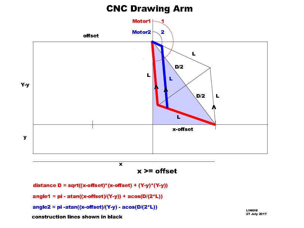
Calculation
The shape of the linkages are selected with the assumption that the vector position of the penholder at the tip can be conveniently solved using geometrical characteristics of a rhombus.
In the picture above the blue and red arms are conneted independently to two stepper motors in one shaft at different heights.
Source://https://www.instructables.com/id/CNC-Drawing-Arm
Materials Required
1. 12V DC stepper motors (200 pulse/rev)
2. A4988 Stepper motor driver for controlling stepper motors microstepping.
3. Arduino UNO
4. Servo motor for controlling the pentip.
5. DC power supply source of 12v.
6. GT2 20 teeth,5mm core dia,6mm width pulley of 2nos
7. GT2 80 teeth,5mm core dia,6mm width pulley of 2nos
8. 6mm wide pulley belt of 2 nos
9. 5mm dia shaft rod approximately 10 cm long.
10. 5mm nuts and washers.
11. 608 ZZ roller bearingsof 2 of nos
12. 6mm Coller lock at top
13. Plywood(4*4) of 12 mm thickneness
14. Acrylic(6mm and 2mm ) sheets are used to make linkages
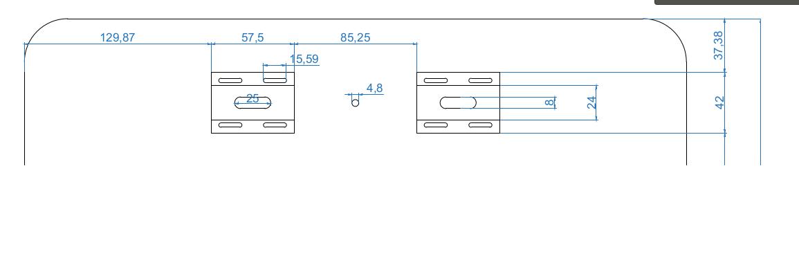
Design
The CAD design of the machine was done in Rhinoceros.
Since GT2 80 teeth pulley was not available at the lab we decided to 3d print the pulley after designing it in Rhino.
Assembly
The components used for the assembly were
1. Central Shaft a 5mm lead screw thread
2. Roller Bearing 608 zz 2 nos
3. 3D printed GT2 80 teeth PLA pulleys 2 nos
4. 3D printed arms of sectional size 25X3mm for the elbow arm and 12.5X1mm elbow driving link
5. Shaft couplers
6. Power 288A MXL 9mm wide trapezoidal pulleys -2 nos
The entire assembly of the stepper motors are mounted on a Plywood sheet of thickness 12mm. Slots for NEMA 17 and
central shafts were drilled on the plywood plank using Shopbot.
The slots were provided in oval shape to account for finer adjustments for tightening the timing belt after fixing the steppers.
 For testing the mechanism we cut the scaled sizes of the plotting arm in pvc and fixed it to the plywood base to simulate the plotter arms motions.
The pvc panels are screwed at the joints to simulate hinges at the joints.
For testing the mechanism we cut the scaled sizes of the plotting arm in pvc and fixed it to the plywood base to simulate the plotter arms motions.
The pvc panels are screwed at the joints to simulate hinges at the joints.
 The arms are pivoted at the base and checked for free motion of the arms to understand the behaviour of the lnkages.
 Source://https://www.instructables.com/id/CNC-Drawing-Arm
 Since GT2 80 teeth pulley was not available at the lab we decided to 3d print the pulley after designing it in Rhino.

 The slots were provided in oval shape to account for finer adjustments for tightening the timing belt after fixing the steppers.