Final Project
Summary
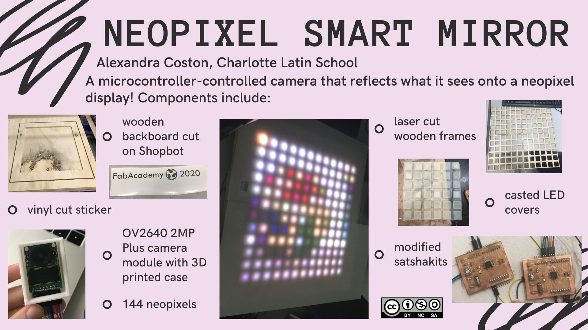
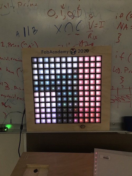
For my final project, I made a neopixel smart mirror that used a camera as an input device to display the image data it took onto neopixels. This “mirror” incorporated a wooden backboard milled on the Shopbot, laser-cut wooden frames, casted LED covers, a vinyl sticker, and a 3D printed camera case. Additionally, I used modified satshakits that communicated with each other to take pictures with the camera and send the data to the neopixels. You can view my summary slide and video below:
In week 13, I decided I would publish my work under a Creative Commons Attribution-NonCommercial-ShareAlike 4.0 International (CC BY-NC-SA 4.0) License. This was a result of my Neopixel Smart Mirror being inspired by another person’s project, in addition to the fact that it is intended for personal use and is a creative display, so I will not attempt to sell it or gain any profit off of it. This license allows others to copy, remix, and share the material as long as they give credit to the creator, refrain from using the project for commercial purposes, and apply the same license on the transformed project as the original.

That being said, you can download all my files for my final project here.
You can watch my peer Vincent Zhou and I present our final projects from 47:58 - 56:43 here:
20200708 projects from Academany on Vimeo.
Bill of Materials
| Item | Price |
|---|---|
| 5m reel of Neopixels (30 LEDS/m) | $84.75 |
| 5V 10A Power Supply | $18.99 |
| Arducam 2MP Plus OV2640 Mini Module SPI Camera for Arduino UNO Mega2560 Board | $25.99 |
| EcoFlex | $33 |
| 3/4in wood | - |
| 1/8in wood | - |
| 1000uF capacitor | $0.50 |
| 470Ω resistor | $0.05 |
| 2 ATMEGA328P-AUR microcontrollers | $4.16 |
Total: $167.44
Note: Fortunately, all of the materials I used for this project were already available to me in the lab.
Planning
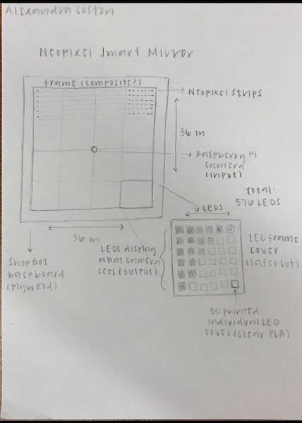
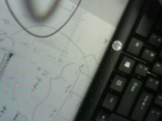
My final project idea was inspired by SuperMakeSomething’s Neopixel LED Mirror. The basis of my project was that it would use a camera input to display what it saw to a grid of Neopixels, creating a mirror-like effect. Here was my initial sketch of what I wanted my project to encompass as was introduced in week 1:
The different components I needed to create and put together included:
- a microcontroller board with a camera input and neopixel output
- 3D printed individual LED covers
- a laser cut frame
- a backboard cut on the Shopbot
SuperMakeSomething’s project used only a Raspberry Pi camera and Raspberry Pi, so I needed to find a way to create my own board and look into different camera options that would work in accordance with the Neopixels. Additionally, the original code was in Python. While I browsed this article discussing the 10 best Arduino cameras, I ended up choosing the ArduCam 2MP Plus Camera. I discussed the setup of my final project with this camera with one of my instructors, Dr. Harris, who concluded that in order to make this project I would most likely have to take the data from the camera, put it in an intermediate (Processing), then translate it to the neopixels. You can view the Gantt chart I created during week 18 to guide me in the last stages of me project here.
ArduCam (Input Devices)
Setting it up
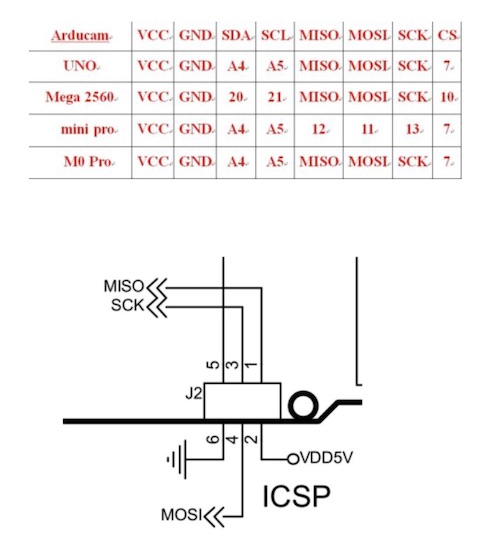
The first step of working on the camera component was to get a video stream working. I downloaded the ArduCam libaries here. ArduCam provided a Quick Start Guide to follow in order to ensure that the hardware worked. I followed the instructions to configure the libraries and opened the example sketch ArduCAM_Mini_2MP_Plus_VideoStreaming. I also used my terminal to download the Host app, which “captures and displays application for all of ArduCAM modules.” I did this by typing curl -O www.arducam.com/downloads/app/ArduCAM_Host_V2.0_Mac.app.zip into the terminal to download the zip file. I hooked up the camera to an Arduino using this table:
Here was my setup:
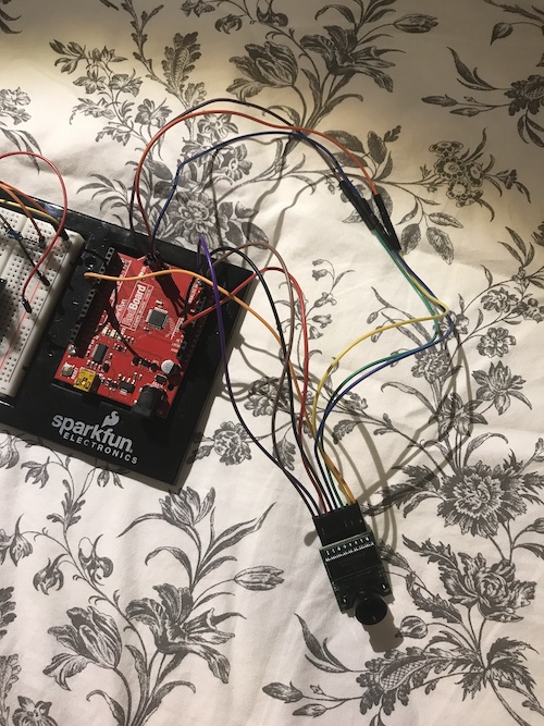
I made sure the memorysaver.h file was in the ArduCAM folder. I made sure the board was an Arduino Uno and the correct port was selected, then uploaded the sketch.
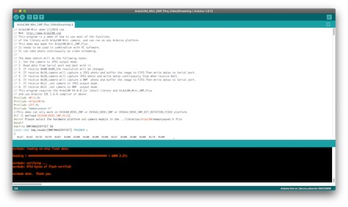
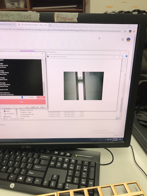
The next step was opening the host application. For some reason, the version of my Mac did not allow me to open the file. As a result, I decided to download it on a PC at the lab to test it. Here is what the host app interface looked like upon opening it:
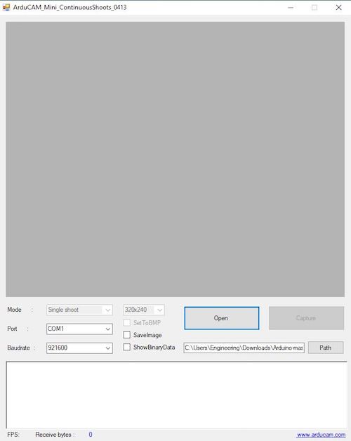
I filled in the appropriate port and baud rate.
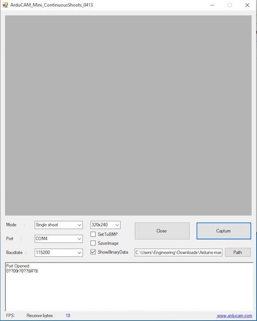
Whenever I tried to press Capture, the serial monitor spit out weird characters and did not open the camera stream. I went back to look at the Arduino code to figure out the issue. I realized that in this statement:
if defined(__SAM3X8E__)
  Wire1.begin();
  Serial.begin(115200);
else
  Wire.begin();
  Serial.begin(921600);
the ‘#if’ was checking to see whether the SAM3X8E was being defined, however it was being used on an Arduino Uno so it was skipping the section where the baud rate was being declared to be 115200 and was going straight to the “#else” which declared to baud rate as 921600. 921600 is a baud rate that Arduinos do not support, so I changed it to be 115200 instead.
if defined(__SAM3X8E__)
  Wire1.begin();
  Serial.begin(115200);
else
  Wire.begin();
  Serial.begin(115200);
When I went back to the host application, the stream worked! The serial port read that the port was opened, the camera was detected, and the video was streaming. You can see my settings and the ArduCam setup below:
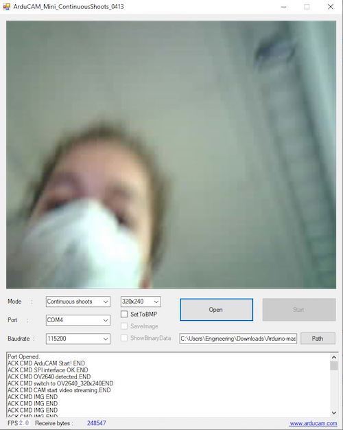
Now that I knew how to use the ArduCam and navigate its interface, I had to set up my neopixels so that I could start writing the code to get the ArduCam’s stream displayed.
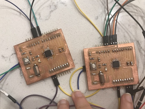
Creating the Board (Electronics Production)
For my custom PCB boards, I decided to use my modified satshakits from week 14. I was really grateful I ended up making two satshakits during this week, because I ultimately used both of them for my final project. You can view the process of producing and coding them during my networking week, but here are how they both turned out:
Frame (Computer Controlled Cutting)
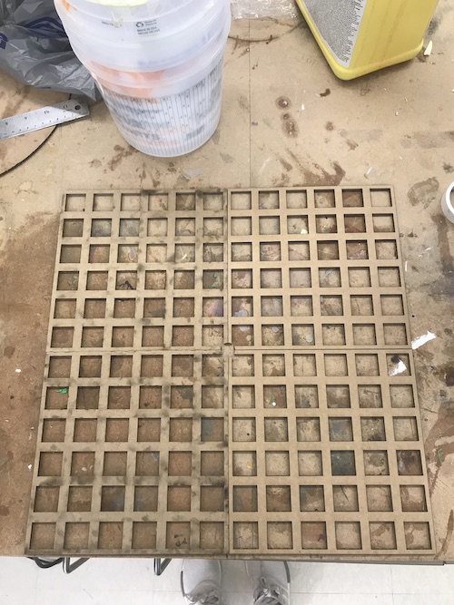
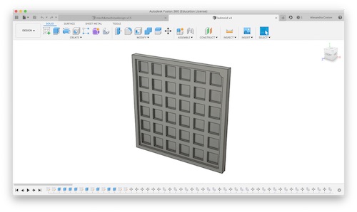
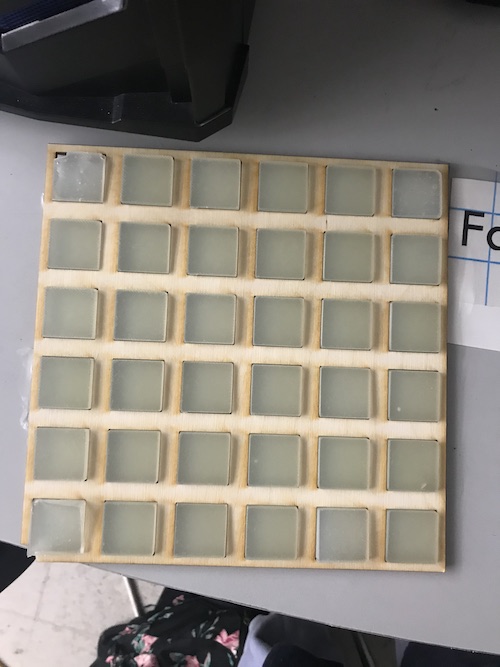
When it came to designing my laser cut frame, I was able to use my design from week 2 that I had designed in Fusion360. That initial design was only a 6x6 grid, so for my final project I expanded it to be a 12x12 grid.
I decided to laser cut the frame out of 1/8” plywood and spray paint it so it would contrast with the backboard.
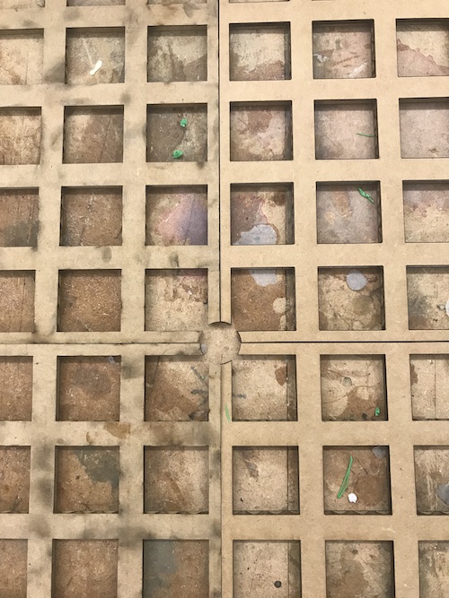
I first made the edges of the frame smaller so that I could fit 4 together and the distance between the pixels would remain the same. I then added a quarter of a circle so that when the 4 frames were fit together, they would create a space for the camera in the center.
I saved the Fusion file as a DXF and opened it in CorelDraw to laser cut. I cut it out of cardboard first, to make sure the sizing and everything was how I wanted it. Everything looked good, so I went ahead and cut it out of ⅛” plywood.
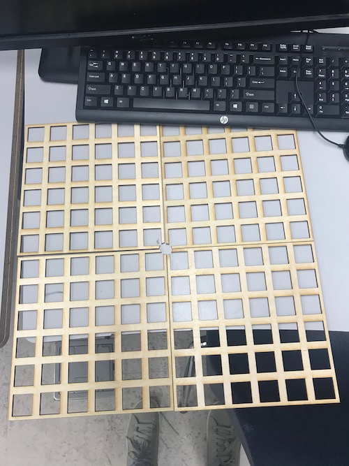
One of the final touches I did towards the end was spray-paint the frames black.
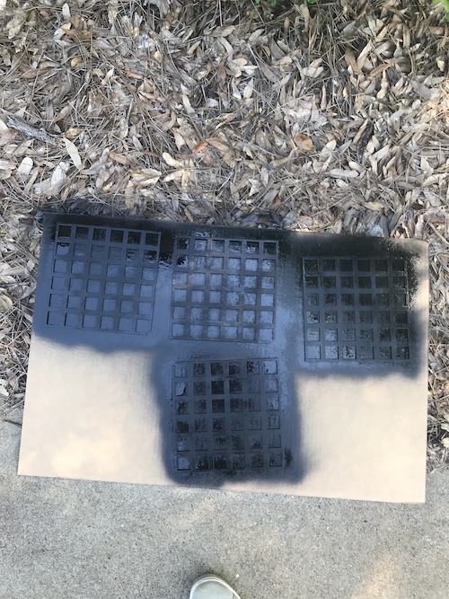
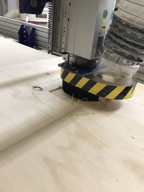
Backboard (Computer Controlled Machining)
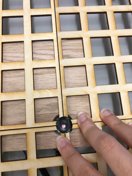
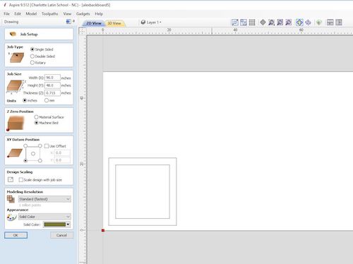
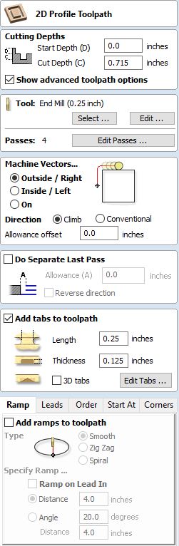
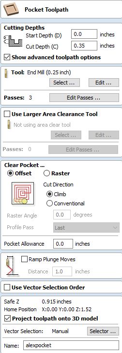
The plan for the backboard was to cut it on the Shopbot and create a pocket cut that the neopixels, frame, and covers would fit into. Because this was a pretty simple design, instead of designing it on Fusion360 like I normally would, I decided to design it straight in Aspire. I made two squares, one size 16.25in x 16.25in and the other 20.4in x 20.4in. The inside square would be the pocket cut where the frame and neopixels would go, while the outside square would be the profile cut. I used the dimensions of the frames and added a bit of clearance. The next step was deciding what size material to use and how deep the pocket cut would be. I initially chose 0.5in wood and would do a pocket cut of 0.35in, which would fit the frames, neopixels, and LED covers with enough room so they would sick in and not stick out. I created the two toolpaths and saved them.
When it came to actually finding my material, there were a lot of large sheets of wood that I did not want to do just a small-scale corner cut on. I found a piece of 0.75in wood that was a good size for my cut. My teacher, Mr. Dubick, then pointed out that I needed to see if the wood was too thick for the camera I was using. My plan was to drill a hole for the camera to peek through, as I similarly did in with the frames using the laser cutter. I took a scrap piece of 0.75in wood and a 7/8in bit and drilled a hole in it. I then set up my camera’s video stream and placed the camera under the wood. Luckily, there was no outline and the camera’s focus remained good. I also placed my laser cut frames on top of it. They also did not interfere with the camera.
This important step led me to change the material thickness in Aspire from 0.5in to 0.715in (not quite three-quarter inches but close). I then recalculated the profile cut. Here are the settings for the document and toolpaths I used:
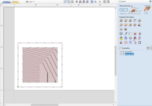
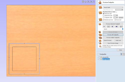
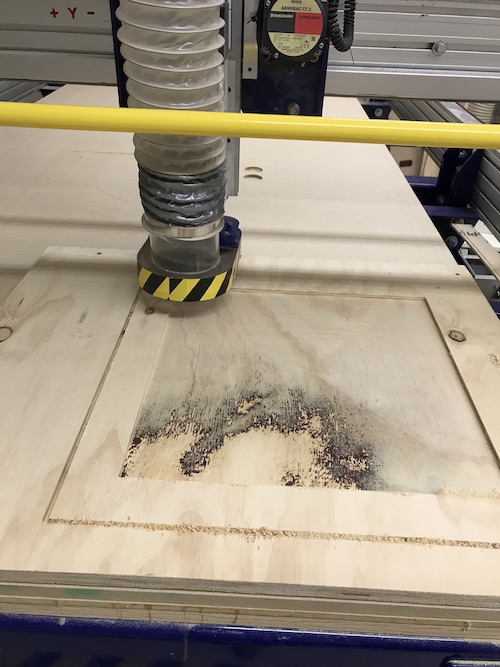
Once the toolpaths were created, I was ready to cut the frame on the Shopbot. I drilled in the wood, zeroed the axes, and made sure the correct bit (0.25in) was inserted. Mr. Dubick told me that for the profile cut, I needed to zero the Z axis off the bed as usual. However, for the pocket cut, I needed to zero the Z axis off of the material. I went back and changed the settings for each toolpath and saved them separately. I ran an aircut of the pocket cut, then seeing that it worked, ran the actual cut. The pocket cut took 3 passes, each pass taking a little under 30 minutes to cut.
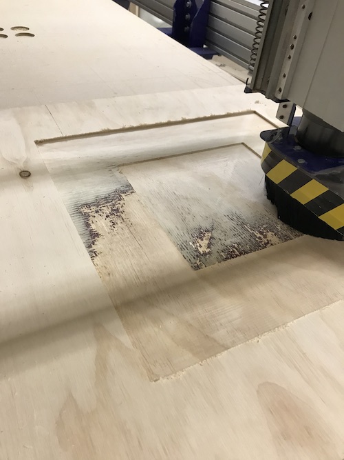
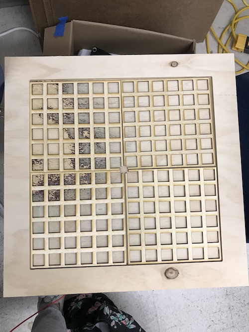
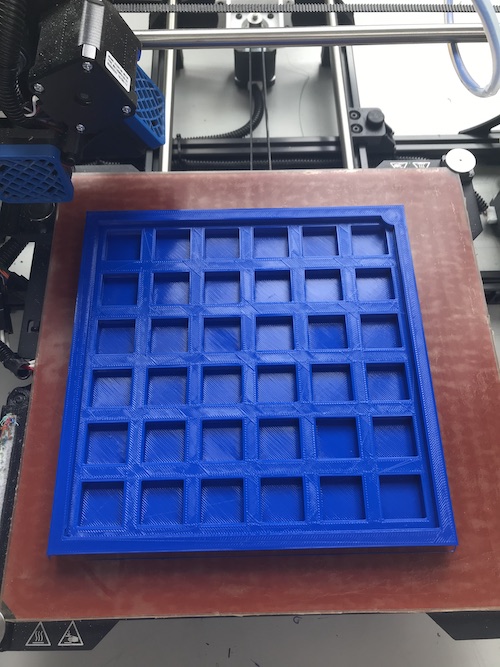
Once the pocket cut was (finally) finished, I ran the profile cut. It only took about 3 minutes. I used a mallet and chisel to break the tabs so I could take out the backboard. Here is how it turned out:
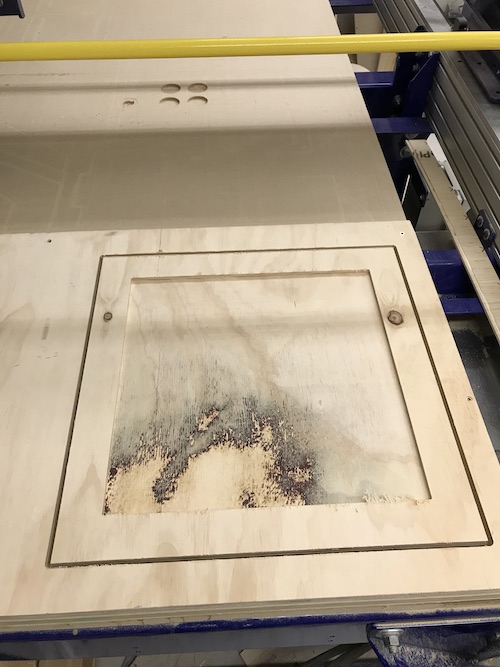
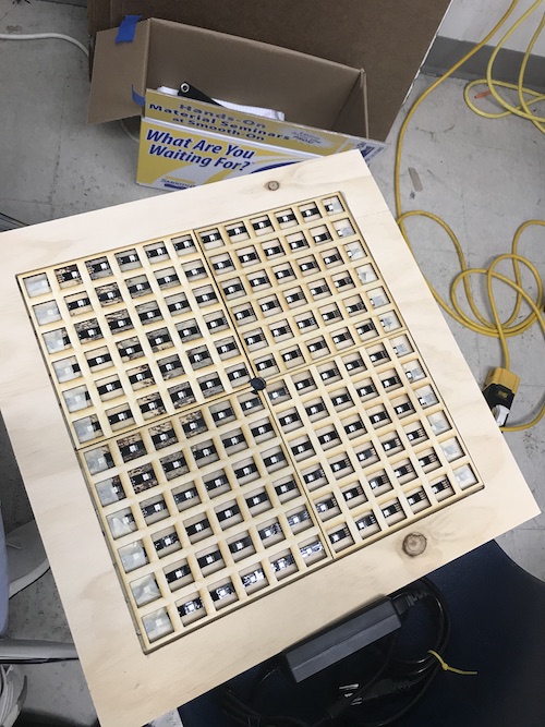
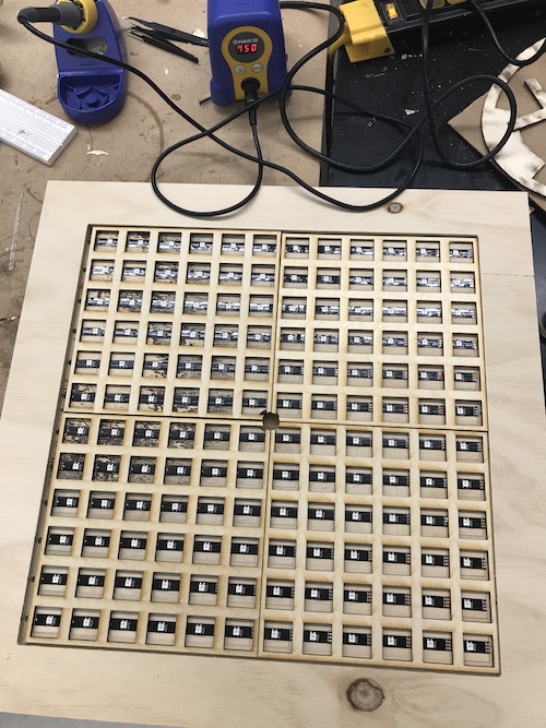
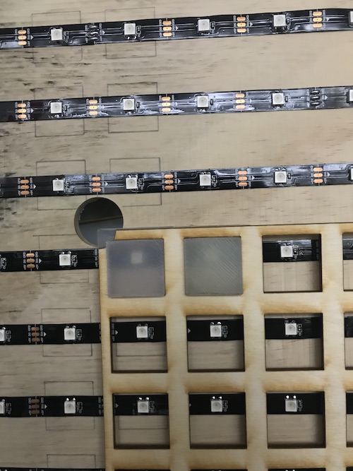
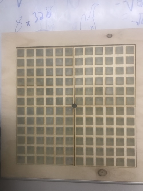
I placed the frames in so I could see the fit. Here is how that looked:
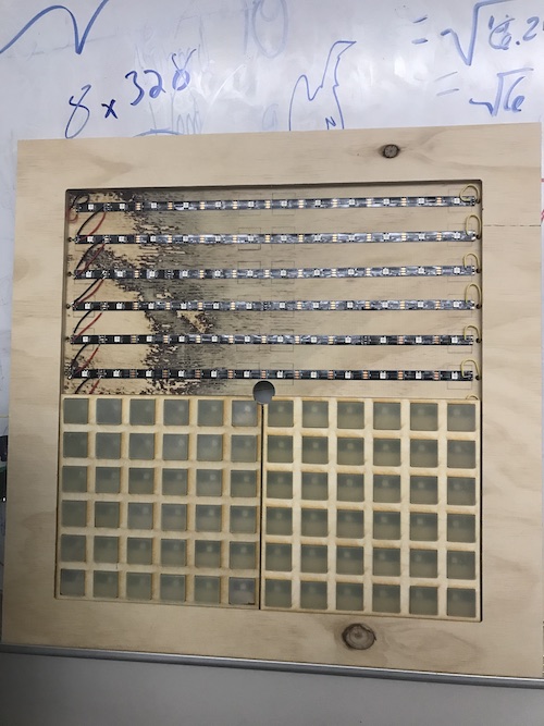
Next, I traced the inside, middle, and outside squares using the frame and drew a line for each row. This would guide me when I placed the neopixels.
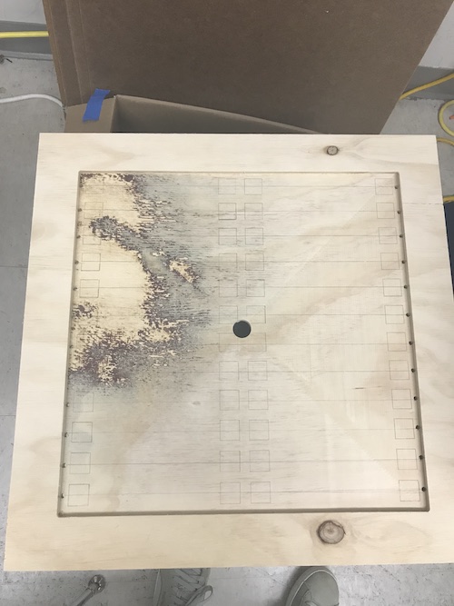
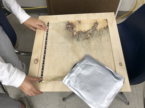
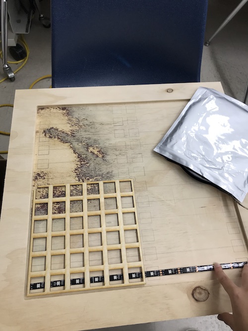
You can see that each pixel would be centered in its own square. The placement looked good so I went ahead and cut the neopixel strips accordingly and used masking tape to temporarily secure them. Everything looked good so far!
Neopixels (Output Devices)
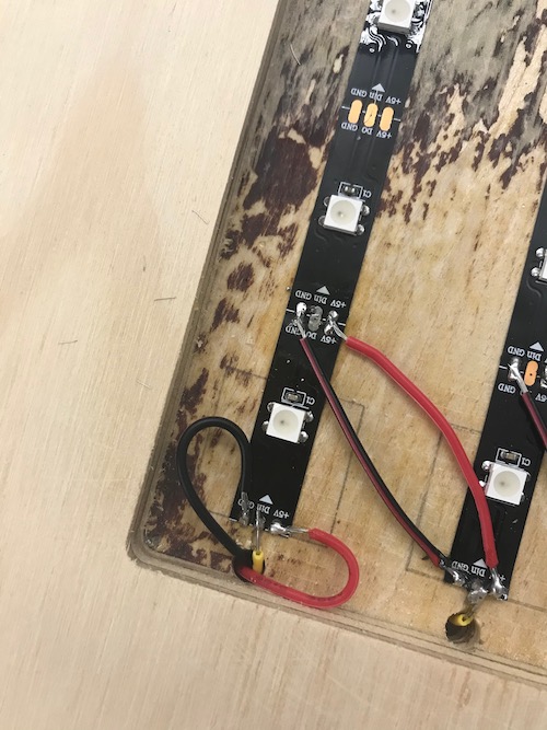
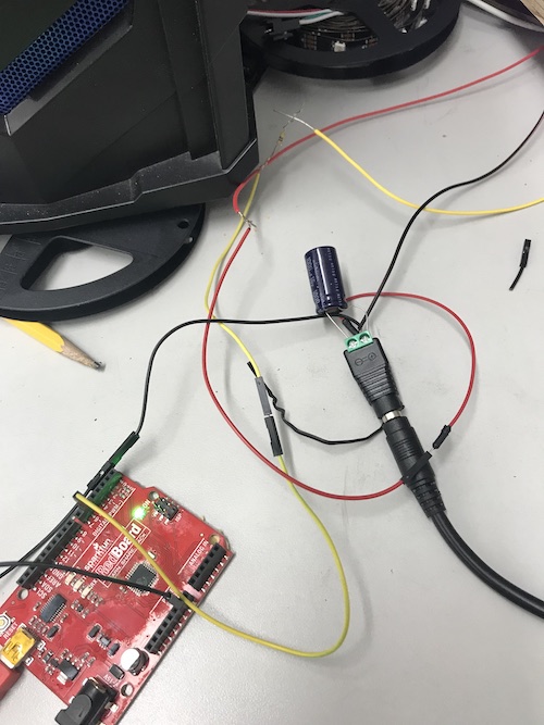
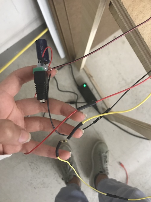
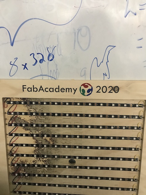
The next step was permenantly adhering the strips and soldering them together. Each strip had an adhesive back so sticking them onto the frame was easy. I decided that I would solder the 5V and GND of each strip together going downwards, then solder the information pin from the right side of the neopixel to the left side of the neopixel strip under it. This way, the neopixels would be read and coded from left to right. In essence, I soldered the 5V and GND pins in parallel, while soldering the information pin of the neopixels in series.
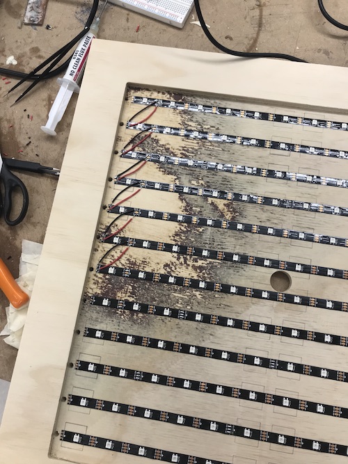
As you can see, 5V is the red wire, GND is the black wire, and D6 is the yellow wire, which wraps around the back of the wood.
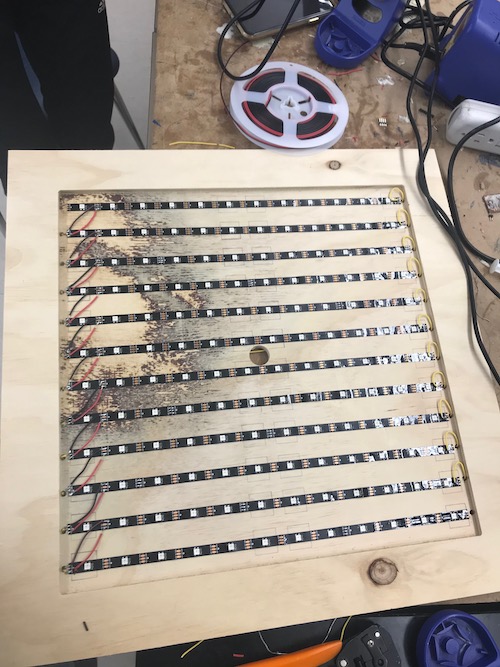
I soldered all three wires to the first neopixel so that they would connect to the Arduino and alternate power source.
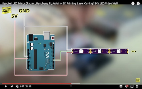
SuperMakeSomething provided a diagram of how to connect the neopixels to an Arduino to test them. The Neopixels have three wires: 5V, GND, and D6.
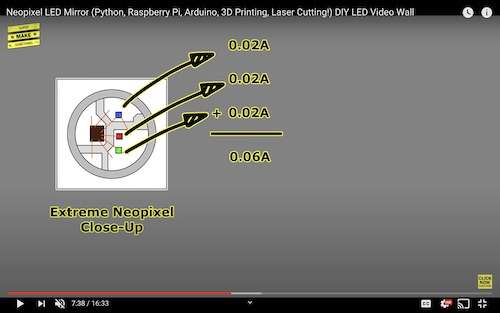
Before I set up all my Neopixels and connected them to power, I needed to calculate how much power they would draw. This diagram from SuperMakeSomething shows a closeup of a Neopixel and how much current each individual LED draws. Because each Neopixel uses 0.06A, and I was planning on using 144 neopixels, that meant that I would need about 9A.
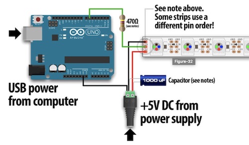
We had a 5V 10A power source at the lab, so this is what I chose to use. I used this as I was setting up my neopixels. The website provided a lot of information about the different kinds of neopixels and how to power and test them. I followed this diagram to connect my neopixels:
Here was my setup:
In order to see if my Neopixels were working, I needed to run some example code on them. The website I followed suggested running Arduino’s strandtest code from the Neopixel library. I first downloaded the libraries by going to Tools -> Manage Libraries and typing in ‘neopixel’. I downloaded Adafruit Neomatrix and Adafruit Neopixel by Adafruit. Once those were installed, I opened up the example code. I changed the LED_COUNT to 144 because that was how many individual neopixels I had. I also made sure D6 was hooked up to pin 6 on the Arduino. I selected Arduino UNO as the board and made sure it was connected to the correct port. I uploaded the code and it worked! My neopixels turned on and had a cool light display. Here is the code and my neopixels working:
// A basic everyday NeoPixel strip test program.

// NEOPIXEL BEST PRACTICES for most reliable operation:
// - Add 1000 uF CAPACITOR between NeoPixel strip's + and - connections.
// - MINIMIZE WIRING LENGTH between microcontroller board and first pixel.
// - NeoPixel strip's DATA-IN should pass through a 300-500 OHM RESISTOR.
// - AVOID connecting NeoPixels on a LIVE CIRCUIT. If you must, ALWAYS
//   connect GROUND (-) first, then +, then data.
// - When using a 3.3V microcontroller with a 5V-powered NeoPixel strip,
//   a LOGIC-LEVEL CONVERTER on the data line is STRONGLY RECOMMENDED.
// (Skipping these may work OK on your workbench but can fail in the field)

#include <Adafruit_NeoPixel.h>
#ifdef __AVR__
 #include <avr/power.h> // Required for 16 MHz Adafruit Trinket
#endif

// Which pin on the Arduino is connected to the NeoPixels?
// On a Trinket or Gemma we suggest changing this to 1:
#define LED_PIN    6

// How many NeoPixels are attached to the Arduino?
#define LED_COUNT 144

// Declare our NeoPixel strip object:
Adafruit_NeoPixel strip(LED_COUNT, LED_PIN, NEO_GRB + NEO_KHZ800);
// Argument 1 = Number of pixels in NeoPixel strip
// Argument 2 = Arduino pin number (most are valid)
// Argument 3 = Pixel type flags, add together as needed:
//   NEO_KHZ800  800 KHz bitstream (most NeoPixel products w/WS2812 LEDs)
//   NEO_KHZ400  400 KHz (classic 'v1' (not v2) FLORA pixels, WS2811 drivers)
//   NEO_GRB     Pixels are wired for GRB bitstream (most NeoPixel products)
//   NEO_RGB     Pixels are wired for RGB bitstream (v1 FLORA pixels, not v2)
//   NEO_RGBW    Pixels are wired for RGBW bitstream (NeoPixel RGBW products)


// setup() function -- runs once at startup --------------------------------

void setup() {
  // These lines are specifically to support the Adafruit Trinket 5V 16 MHz.
  // Any other board, you can remove this part (but no harm leaving it):
#if defined(__AVR_ATtiny85__) && (F_CPU == 16000000)
  clock_prescale_set(clock_div_1);
#endif
  // END of Trinket-specific code.

  strip.begin();           // INITIALIZE NeoPixel strip object (REQUIRED)
  strip.show();            // Turn OFF all pixels ASAP
  strip.setBrightness(50); // Set BRIGHTNESS to about 1/5 (max = 255)
}


// loop() function -- runs repeatedly as long as board is on ---------------

void loop() {
  // Fill along the length of the strip in various colors...
  colorWipe(strip.Color(255,   0,   0), 50); // Red
  colorWipe(strip.Color(  0, 255,   0), 50); // Green
  colorWipe(strip.Color(  0,   0, 255), 50); // Blue

  // Do a theater marquee effect in various colors...
  theaterChase(strip.Color(127, 127, 127), 50); // White, half brightness
  theaterChase(strip.Color(127,   0,   0), 50); // Red, half brightness
  theaterChase(strip.Color(  0,   0, 127), 50); // Blue, half brightness

  rainbow(10);             // Flowing rainbow cycle along the whole strip
  theaterChaseRainbow(50); // Rainbow-enhanced theaterChase variant
}


// Some functions of our own for creating animated effects -----------------

// Fill strip pixels one after another with a color. Strip is NOT cleared
// first; anything there will be covered pixel by pixel. Pass in color
// (as a single 'packed' 32-bit value, which you can get by calling
// strip.Color(red, green, blue) as shown in the loop() function above),
// and a delay time (in milliseconds) between pixels.
void colorWipe(uint32_t color, int wait) {
  for(int i=0; i<strip.numPixels(); i++) { // For each pixel in strip...
    strip.setPixelColor(i, color);         //  Set pixel's color (in RAM)
    strip.show();                          //  Update strip to match
    delay(wait);                           //  Pause for a moment
  }
}

// Theater-marquee-style chasing lights. Pass in a color (32-bit value,
// a la strip.Color(r,g,b) as mentioned above), and a delay time (in ms)
// between frames.
void theaterChase(uint32_t color, int wait) {
  for(int a=0; a<10; a++) {  // Repeat 10 times...
    for(int b=0; b<3; b++) { //  'b' counts from 0 to 2...
      strip.clear();         //   Set all pixels in RAM to 0 (off)
      // 'c' counts up from 'b' to end of strip in steps of 3...
      for(int c=b; c<strip.numPixels(); c += 3) {
        strip.setPixelColor(c, color); // Set pixel 'c' to value 'color'
      }
      strip.show(); // Update strip with new contents
      delay(wait);  // Pause for a moment
    }
  }
}

// Rainbow cycle along whole strip. Pass delay time (in ms) between frames.
void rainbow(int wait) {
  // Hue of first pixel runs 5 complete loops through the color wheel.
  // Color wheel has a range of 65536 but it's OK if we roll over, so
  // just count from 0 to 5*65536. Adding 256 to firstPixelHue each time
  // means we'll make 5*65536/256 = 1280 passes through this outer loop:
  for(long firstPixelHue = 0; firstPixelHue < 5*65536; firstPixelHue += 256) {
    for(int i=0; i<strip.numPixels(); i++) { // For each pixel in strip...
      // Offset pixel hue by an amount to make one full revolution of the
      // color wheel (range of 65536) along the length of the strip
      // (strip.numPixels() steps):
      int pixelHue = firstPixelHue + (i * 65536L / strip.numPixels());
      // strip.ColorHSV() can take 1 or 3 arguments: a hue (0 to 65535) or
      // optionally add saturation and value (brightness) (each 0 to 255).
      // Here we're using just the single-argument hue variant. The result
      // is passed through strip.gamma32() to provide 'truer' colors
      // before assigning to each pixel:
      strip.setPixelColor(i, strip.gamma32(strip.ColorHSV(pixelHue)));
    }
    strip.show(); // Update strip with new contents
    delay(wait);  // Pause for a moment
  }
}

// Rainbow-enhanced theater marquee. Pass delay time (in ms) between frames.
void theaterChaseRainbow(int wait) {
  int firstPixelHue = 0;     // First pixel starts at red (hue 0)
  for(int a=0; a<30; a++) {  // Repeat 30 times...
    for(int b=0; b<3; b++) { //  'b' counts from 0 to 2...
      strip.clear();         //   Set all pixels in RAM to 0 (off)
      // 'c' counts up from 'b' to end of strip in increments of 3...
      for(int c=b; c<strip.numPixels(); c += 3) {
        // hue of pixel 'c' is offset by an amount to make one full
        // revolution of the color wheel (range 65536) along the length
        // of the strip (strip.numPixels() steps):
        int      hue   = firstPixelHue + c * 65536L / strip.numPixels();
        uint32_t color = strip.gamma32(strip.ColorHSV(hue)); // hue -> RGB
        strip.setPixelColor(c, color); // Set pixel 'c' to value 'color'
      }
      strip.show();                // Update strip with new contents
      delay(wait);                 // Pause for a moment
      firstPixelHue += 65536 / 90; // One cycle of color wheel over 90 frames
    }
  }
}
Once I knew the neopixels were working, I needed to see if I could get a bitmap image to be displayed on them. Dr. Harris found a video that showed how to turn images into Arduino arrays for the neopixel display.
The first step was getting the image. I went to this website and got a sheet of the characters from PacMan (because I like PacMan and used to play it when I was younger).
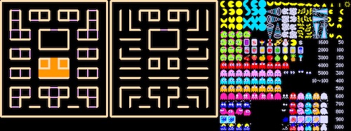
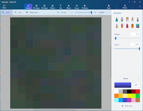
I chose two images from the sheet, two of the red ghosts, so that an animation would be created of the ghost moving its eyes up and down. The next step was cropping the sheet and saving the two images separately. I needed to crop them to be 12 pixels x 12 pixels because that was the size of my neopixel display. The man in the tutorial used Photoshop, but I didn’t have it so I used Paint3D on my lab’s PC. I saved the images separately and changed them to .BMP formats.
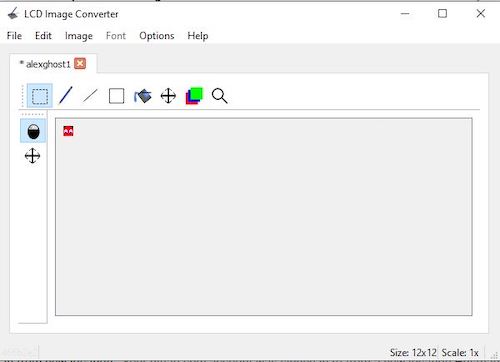
From there, I had to download the LCD Image Converter in order to get the values for the neopixels that would go in the code. I opened the first image:
I first when to Images -> Conversion and then changed the type from Monochrome to Color.
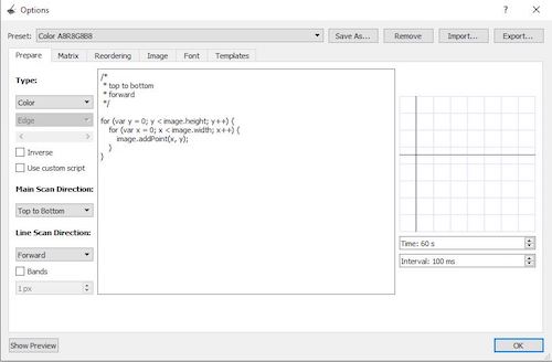
I then clicked Image and changed 8 bit to 24 bit.
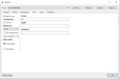
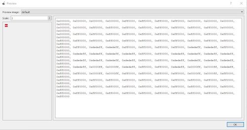
Next, I clicked Show Preview to generate the array. As you can see, there are 144 values that are in HTML color format that will tell each individual neopixel what to do.
I clicked OK and saved the changes, and then repeated this process for the other image. Next, I pulled up the code. The code wrote to the flash of the Arduino Uno and used the FastLED library to control the neopixels. I once again changed the NUM_LEDS to 144 and changed the DATA-PIN to 6. I named my arrays Ghost01 and Ghost02, then pasted in the values from the LCD converter.
/* Arduino 256 RGB LEDs Matrix Animation Frame
 * Using WS2812 LED Strips

Created by Yvan / https://Brainy-Bits.com

This code is in the public domain...

You can: copy it, use it, modify it, share it or just plain ignore it!
Thx!

*/

#include <avr/pgmspace.h>  // Needed to store stuff in Flash using PROGMEM
#include "FastLED.h"       // Fastled library to control the LEDs

// How many leds are connected?
#define NUM_LEDS 144

// Define the Data Pin
#define DATA_PIN 6  // Connected to the data pin of the first LED strip

// Define the array of leds
CRGB leds[NUM_LEDS];

// Create the array of retro arcade characters and store it in Flash memory
const long Ghost01[] PROGMEM =
{
0x000000, 0x000000, 0x000000, 0x000000, 0xff0000, 0xff0000, 0xff0000, 0xff0000, 0x000000, 0x000000, 0x000000, 0x000000,
0x000000, 0x000000, 0xff0000, 0xff0000, 0xff0000, 0xff0000, 0xff0000, 0xff0000, 0xff0000, 0xff0000, 0x000000, 0x000000,
0x000000, 0xff0000, 0xff0000, 0xff0000, 0xff0000, 0xff0000, 0xff0000, 0xff0000, 0xff0000, 0xff0000, 0xff0000, 0x000000,
0xff0000, 0xff0000, 0xff0000, 0xff0000, 0xff0000, 0xff0000, 0xff0000, 0xff0000, 0xff0000, 0xff0000, 0xff0000, 0xff0000,
0xff0000, 0xff0000, 0xdedeff, 0xdedeff, 0xff0000, 0xff0000, 0xff0000, 0xff0000, 0xdedeff, 0xdedeff, 0xff0000, 0xff0000,
0xff0000, 0xdedeff, 0xdedeff, 0xdedeff, 0xdedeff, 0xff0000, 0xff0000, 0xdedeff, 0xdedeff, 0xdedeff, 0xdedeff, 0xff0000,
0xff0000, 0xdedeff, 0xdedeff, 0xdedeff, 0xdedeff, 0xff0000, 0xff0000, 0xdedeff, 0xdedeff, 0xdedeff, 0xdedeff, 0xff0000,
0xff0000, 0xdedeff, 0x0000ff, 0x0000ff, 0xdedeff, 0xff0000, 0xff0000, 0xdedeff, 0x0000ff, 0x0000ff, 0xdedeff, 0xff0000,
0xff0000, 0xff0000, 0x0000ff, 0x0000ff, 0xff0000, 0xff0000, 0xff0000, 0xff0000, 0x0000ff, 0x0000ff, 0xff0000, 0xff0000,
0xff0000, 0xff0000, 0xff0000, 0xff0000, 0xff0000, 0xff0000, 0xff0000, 0xff0000, 0xff0000, 0xff0000, 0xff0000, 0xff0000,
0xff0000, 0xff0000, 0xff0000, 0xff0000, 0xff0000, 0xff0000, 0xff0000, 0xff0000, 0xff0000, 0xff0000, 0xff0000, 0xff0000,
0xff0000, 0xff0000, 0xff0000, 0xff0000, 0xff0000, 0xff0000, 0xff0000, 0xff0000, 0xff0000, 0xff0000, 0xff0000, 0xff0000
};

const long Ghost02[] PROGMEM =
{
0x000000, 0x000000, 0x000000, 0x000000, 0xff0000, 0xff0000, 0xff0000, 0xff0000, 0x000000, 0x000000, 0x000000, 0x000000,
0x000000, 0x000000, 0x0000ff, 0x0000ff, 0xff0000, 0xff0000, 0xff0000, 0xff0000, 0x0000ff, 0x0000ff, 0x000000, 0x000000,
0x000000, 0xdedeff, 0x0000ff, 0x0000ff, 0xdedeff, 0xff0000, 0xff0000, 0xdedeff, 0x0000ff, 0x0000ff, 0xdedeff, 0x000000,
0xff0000, 0xdedeff, 0xdedeff, 0xdedeff, 0xdedeff, 0xff0000, 0xff0000, 0xdedeff, 0xdedeff, 0xdedeff, 0xdedeff, 0xff0000,
0xff0000, 0xdedeff, 0xdedeff, 0xdedeff, 0xdedeff, 0xff0000, 0xff0000, 0xdedeff, 0xdedeff, 0xdedeff, 0xdedeff, 0xff0000,
0xff0000, 0xff0000, 0xdedeff, 0xdedeff, 0xff0000, 0xff0000, 0xff0000, 0xff0000, 0xdedeff, 0xdedeff, 0xff0000, 0xff0000,
0xff0000, 0xff0000, 0xff0000, 0xff0000, 0xff0000, 0xff0000, 0xff0000, 0xff0000, 0xff0000, 0xff0000, 0xff0000, 0xff0000,
0xff0000, 0xff0000, 0xff0000, 0xff0000, 0xff0000, 0xff0000, 0xff0000, 0xff0000, 0xff0000, 0xff0000, 0xff0000, 0xff0000,
0xff0000, 0xff0000, 0xff0000, 0xff0000, 0xff0000, 0xff0000, 0xff0000, 0xff0000, 0xff0000, 0xff0000, 0xff0000, 0xff0000,
0xff0000, 0xff0000, 0xff0000, 0xff0000, 0xff0000, 0xff0000, 0xff0000, 0xff0000, 0xff0000, 0xff0000, 0xff0000, 0xff0000,
0xff0000, 0xff0000, 0xff0000, 0xff0000, 0xff0000, 0xff0000, 0xff0000, 0xff0000, 0xff0000, 0xff0000, 0xff0000, 0xff0000,
0xff0000, 0xff0000, 0xff0000, 0xff0000, 0xff0000, 0xff0000, 0xff0000, 0xff0000, 0xff0000, 0xff0000, 0xff0000, 0xff0000
};

void setup() {
FastLED.addLeds<NEOPIXEL,DATA_PIN>(leds, NUM_LEDS);  // Init of the Fastled library
FastLED.setBrightness(15);
}

void loop() {


// Put Ghost01 first frame
for(int passtime = 0; passtime < 8; passtime++) { // Display it 8 times

FastLED.clear();
for(int i = 0; i < NUM_LEDS; i++) {
    leds[i] = pgm_read_dword(&(Ghost01[i]));  // Read array from Flash
  }

FastLED.show();
delay(500);


// Put Ghost02 second frame
FastLED.clear();
for(int i = 0; i < NUM_LEDS; i++) {
    leds[i] = pgm_read_dword(&(Ghost02[i]));
  }

FastLED.show();
delay(500);

}


}
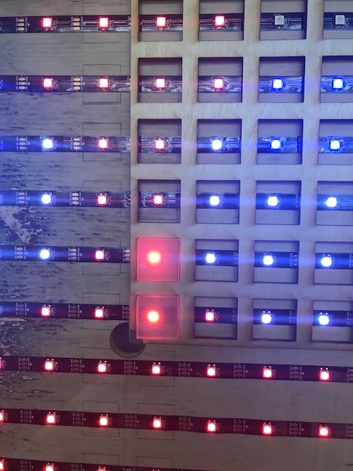
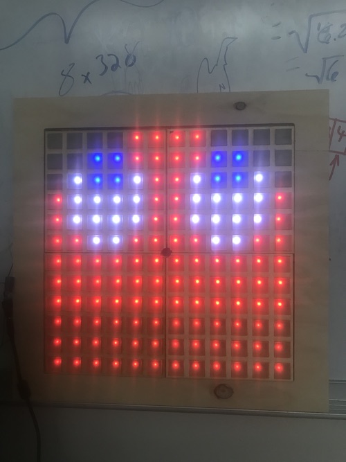
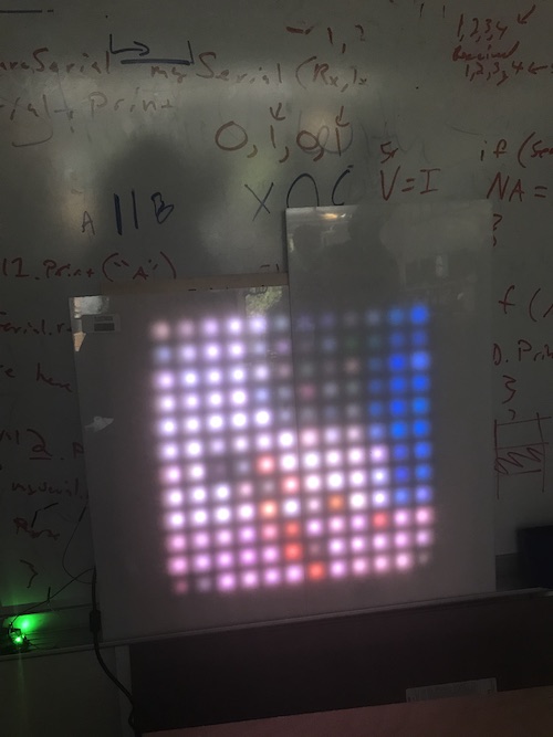
I uploaded the code and it worked! It was a bit difficult to see the ghost itself because of the small number of pixels and the fact that I did not have anything diffusing the light yet, but you can kind of see the reflection in the computer screen behind it.
One of the final things I did, once I knew my wire setup was correct and everything was working properly, was hot glue the capacitor and wires and use heat shrink on the wires. This ensured that nothing would come loose and made it look a bit neater:
LED Covers (3D Printing, Molding & Casting)
Thought I had already designed the LED covers in week 2, I decided to take a different approach for my project. My teacher, Mr. Dubick, showed me this poster and inspired me to create a cast for my LED covers instead.

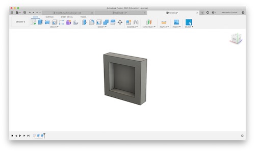
I had originally wanted there to be an opening for the light to shine through, but creating a mold and cast would be pretty efficient. I went ahead and used my week 3 frame design to guide me in designing my mold. I decided I would make the mold the same size as the frame, then cast it four times. Here is a picture of my Fusion design:
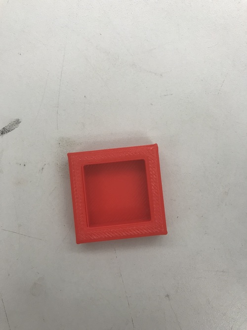
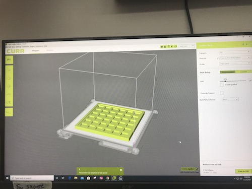
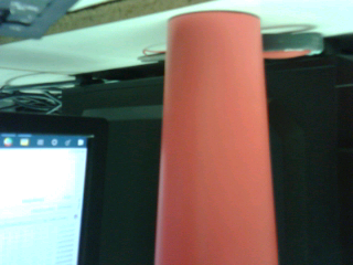
My plan was to use Ecoflex as I had in week 15, this time for my cast instead of my mold, because my lab had an abundance of it and it was slightly translucent. I decided that it would probably be a good idea if I tested it out first by creating a cast the size of one LED cover and turning my lights on to see how the light was diffused. I created a small mold to 3D print:
It was a fast 20 minute print and came out well:
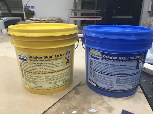
While looking for the Ecoflex in my lab, I stumbled upon some Smooth-On Dragon Skin 10 NV. Neither my peers nor I had used Dragon Skin in our individual or group assignments, so I looked at the datasheet to see how it was different from what I had used.
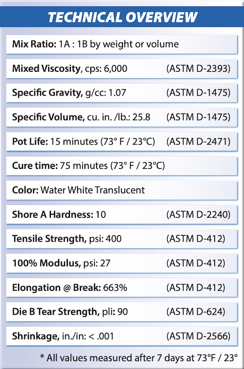
The technical overview gives a summary of the important things to know about Dragon Skin. I learned that I should mix parts A and B in a 1:1 ratio, that it came out “water white translucent” when dry, that the mixture took about 15 minutes to begin settling, and that it took approximately 75 minutes to completely dry.
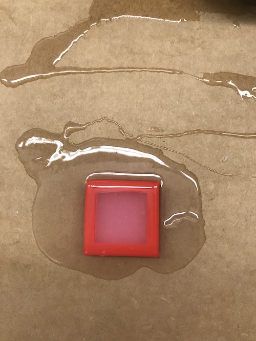
Because I was looking for something translucent to diffuse the light of my neopixels, I decided to try creating casts out of both Ecoflex and Dragon Skin. I printed another small mold while I mixed together equal parts of A and B for EcoFlex. Here is the mixture poured into the mold:
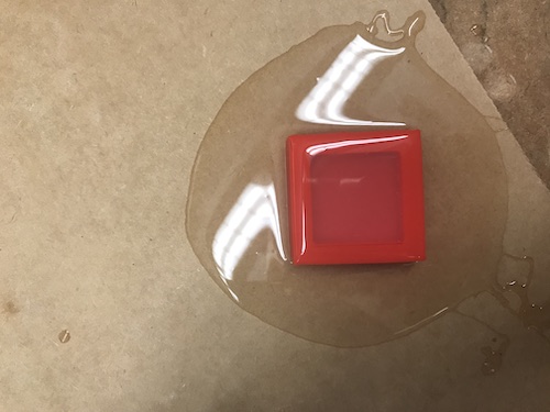
I then repeated this process for the Dragon Skin.
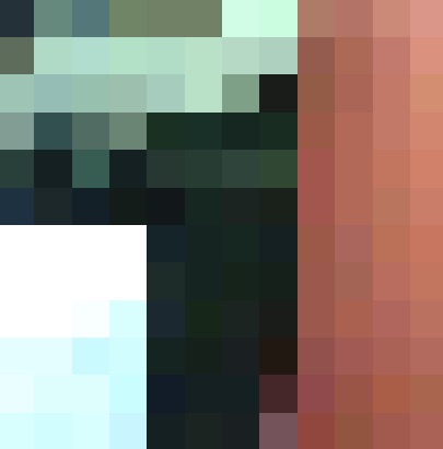
Once both casts were dry, I turned on my neopixels to compare how well the two diffused the light. Here is the EcoFlex on top and the Dragon Skin on the bottom:
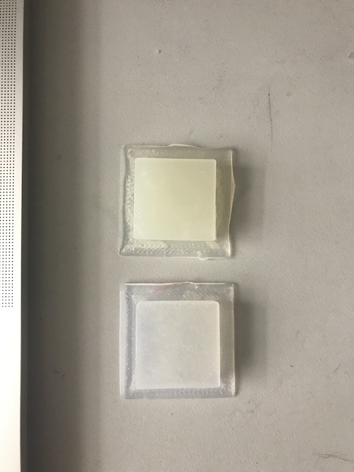
It is a bit difficult to tell from the picture, but I deduced that the EcoFlex diffused the light a bit better because it was off-white and slightly less translucent.
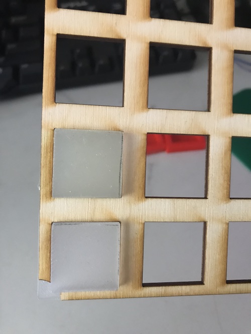
In this picture, the EcoFlex is on the right and the Dragon Skin is on the left:
Now that I knew how the LEDs would look with the covers and with material I wanted to use, I went ahead and 3D printed my large mold. Here is the design:
The print came out perfectly!
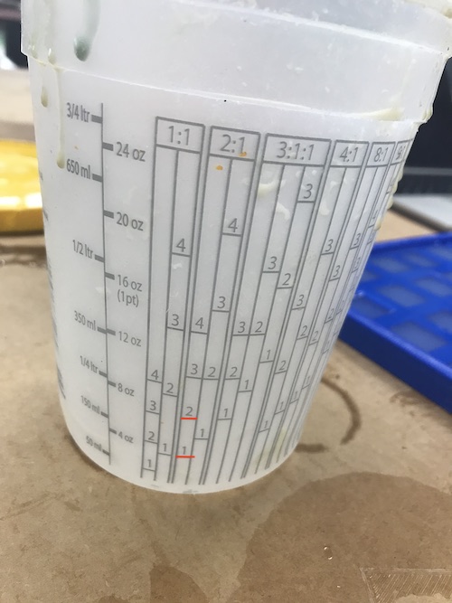
The next step was creating the cast. I combined parts A and B of Ecoflex in a 1:1 ratio. I was just eye-balling how much I needed the first time, so I ended up having just under enough to completely fill the mold:
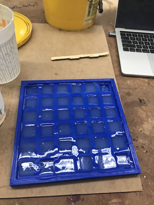
The next time, I increased how much of each part I put. I poured part A into the 1 marked below, then poured part B until it reached the 2. This was the perfect amount!
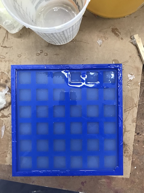
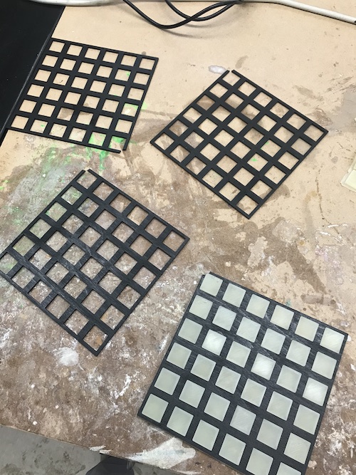
It took only about 10 minutes for each cast to dry. Here is what it looked like out of the mold:
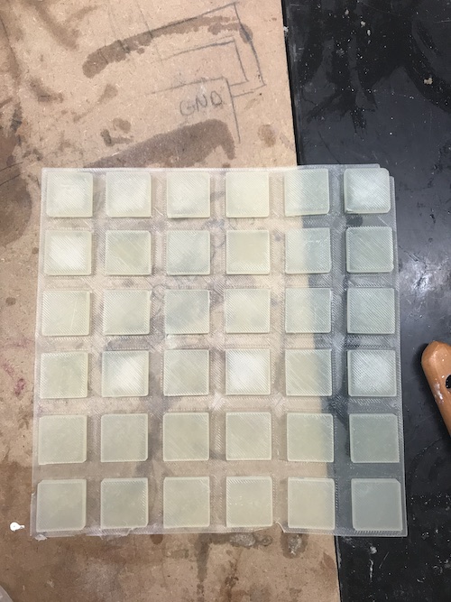
It fit perfectly in the frame and diffused the light pretty well:
Here is the process of putting everything together and testing to see how it looked:
Vinyl Sticker (Computer Controlled Cutting)
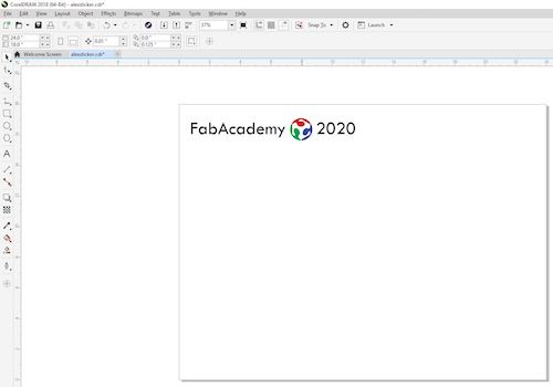
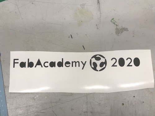
I thought it would be cute to put a sticker on the frame. I decided to just use text to simply write “FabAcademy 2020.” I then imported an image of the FabLab logo, traced the bitmap as a detailed logo, and scaled it down. I did this using CorelDRAW, and you can see my design here:
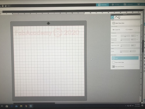
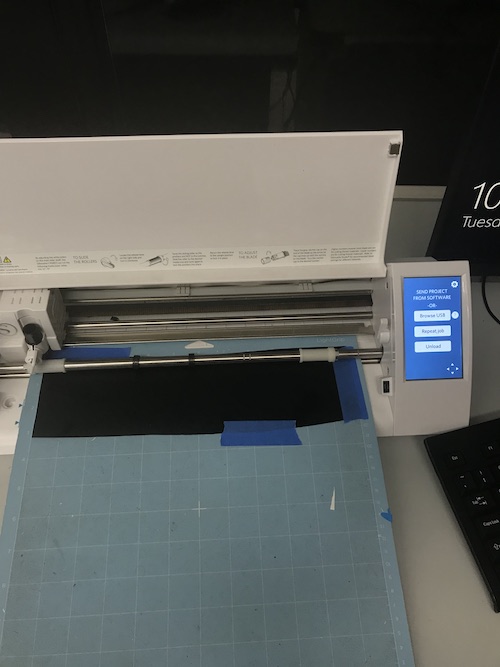
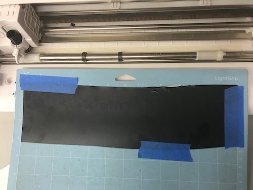
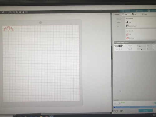
I saved the file as an .svg and then opened it in Silhouette Studio. I traced the design and cut it on matte black vinyl.
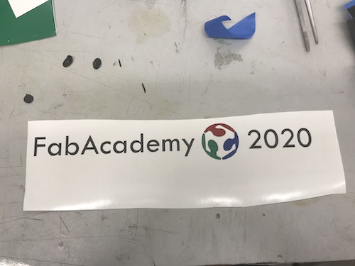
I then needed to cut the red, green, and blue pieces for the FabLab logo. I selected just the top of the logo to trace and cut it three separate times on three small strips of vinyl. I then put those pieces on top of the black one to help line everything up. It came out pretty well!
Finally, I put some transfer paper on top so I could stick in on my frame.
Here is it on the frame!
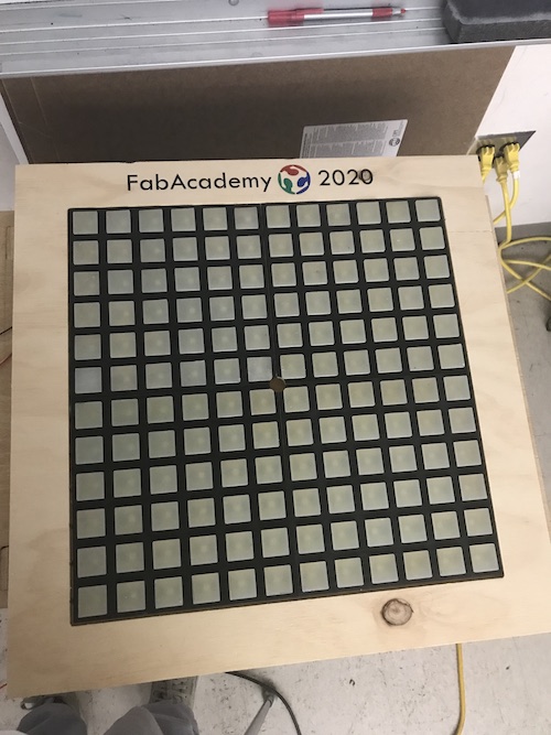
I superglued each cast to the newly spray-painted frames, then glued them to the backboard. Here’s how they looked:
Camera Case (3D Printing)
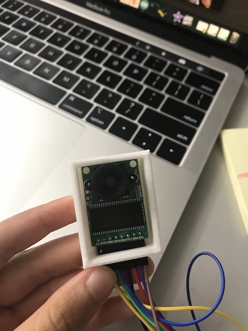
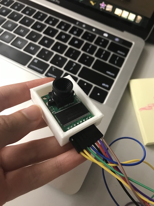
To incorporate 3D printing into my project (I had already created the 3D printed mold, but it was not a part of my actual project) I decided to 3D print a case for my camera. It was a really simple Fusion360 design, with space for the camera and the wires that were attached to it:
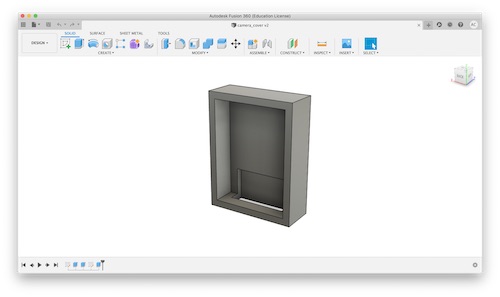
The print only took about 30 minutes, and the camera fit in it well. I used parameters to design it, though I probably did not need to. I ended up gluing it to the back of my backboard later on after I had finished the electronics.
Writing the Code (Embedded Programming)
Once I knew that my camera and neopixels would work on their own, I needed to figure out how they would work together. Throughout the process of creating the code for my project, Dr. Harris was invaluable in helping me write it.
Getting a 12x12 Image
To begin, Dr. Harris found this blogpost of someone who had used an ArduCam to create a time lapse. He used the OV2640 Camera Module, in addition to the ArduCam Rev. B Shield ,and an Arduino UNO. The author of the blog actually expressed his discontent with the ArduCam as a result of its poor resolution and high power need. Nonetheless, I downloaded the first iteration of his code and began looking at which parts I did and did not need. There were several vital sections that exhibited the same functions that I would need.
In the void setup, it begins with
//Initialize I2C Bus
  Wire.begin();
  //Switch to FIFO Mode
  myCAM.write_reg(ARDUCHIP_TIM, MODE_MASK);
  //Initialize Camera Module
  myCAM.InitCAM();
  //Initialize SD Card
  //SD.begin(SD_CS);
FIFO mode, or first-in first-out, is defined as “a method for organising the manipulation of a data structure – often, specifically a data buffer – where the oldest (first) entry, or ‘head’ of the queue, is processed first.” This is how the data coming in will be processed. Once this mode is switched onm the ArduCam is initialized. As you can see, I commened out initializing the SD card because though the guy used an SD card for his project, I will be writing the data to the EEPROM or even straight to the microcontroller.
In the void loop, several characters and integers are introduced.
char buffer[9];
  char filename[14];
  char VH, VL;
  File outFile, counterFile;
  uint8_t temp,temp_last;
  int i, j, posn, nextNum;
I commented out a lot of code after this that opened the counter file for the SD card and created the file name according to what picture number was taken. Here was the next important part:
//Flush the FIFO
  myCAM.flush_fifo();
  //Start capture
  myCAM.start_capture();

  // Wait for the capture to finish
  while (!(myCAM.read_reg(ARDUCHIP_TRIG) & CAP_DONE_MASK)) {
   delay(10);
  }
The FIFO is flushed and the camera takes the pictures. This next part is the most important and useful piece of the code. The FIFO is enabled and the bytes of data are read from it.
//Enable FIFO
  myCAM.enable_fifo();
  //Read the first dummy byte from FIFO
  temp = myCAM.read_fifo();
  //Read 320x240x2 byte from FIFO
  for(i = 0; i < 240; i++)
    for(j = 0; j < 320; j++)
    {
      VH = myCAM.read_fifo();
      VL = myCAM.read_fifo();
Once I had gone through and commented out the unnecessary sections and understood which parts were vital to my own code, I could begin adding additional things. I first switched out the camera type for my camera, the OV2640 Mini 2MP Plus, and changed the bmp image offset accordingly.
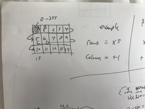
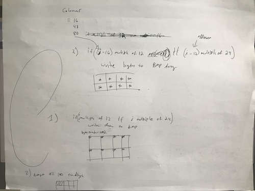
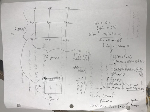
Dr. Harris explained to me that when looking at a pixel array, it is not rows and columns as we see it visually but one long string. He told me that in order to write my code so that a compressed version of the image data would be written to the bitmap image, we would need to create an algorithm that would take a point from each pixel to write. Because the original size of the image was 320x240, we planned to divide this by 10 to create an image 32x24 pixels, then shave off the pixels to end with my frame size of 12x12. This is an example visual Dr. Harris drew to explain the array and the algorithm to me. As you go down a row, you add 5. As you ogo over a column, you add however many you go over. This means that if you multiply the row number by 5 and add however many you go over 1-4, you get the pixel number.
With this in mind, Dr. Harris created three situations that we would build up to in the code. The first was writing data to the bitmap if integer j was a multiple of 32 and i was a multiple of 24. This would write the top left corner of each overall pixel. The next was writing data to the bitmap if j-16 was a multiple of 32 and i-12 was a multiple of 24. This would write the center of each overall pixel. The last situation would take the average of all 100 readings and write them for each pixel.
I wrote the statement for the first situation to attempt to get the data to be written to the serial monitor with an if statement:
if (i%24==0 && j%32==0) {
    // image data to serial monitor
    Serial.print(VL);
    Serial.print(VH);
}
The code did not compile and gave errors regarding the FastLED library for the neopixels and other things I could not figure out how to solve. After looking at it with Dr. Harris, we began going in a different direction, using ArduCam’s own ArduCAM_Mini_2MP_Plus_functions code. We looked through the code to see what parts we needed and which we didn’t. This allowed me to begin commenting out a multitude of statements to save some memory in the Arduino. The sketch contained different cases that specified different parameters, which were controlled by the user in the Host application. The cases we paid attention to were cases 0, 30, and 31. Case 0 was a default–it set the resolution of the camera to 320x240.
case 0:
      myCAM.OV2640_set_JPEG_size(OV2640_160x120);delay(1000);
      Serial.println(F("ACK CMD switch to OV2640_160x120 END"));
     temp = 0xff;
    break;
Case 31 set the format of the image to a BMP as opposed to the default, a JPEG.
case 0x31:
    temp = 0xff;
    myCAM.set_format(BMP);
    myCAM.InitCAM();
    #if !(defined (OV2640_MINI_2MP_PLUS))
    myCAM.clear_bit(ARDUCHIP_TIM, VSYNC_LEVEL_MASK);
    #endif
    myCAM.wrSensorReg16_8(0x3818, 0x81);
    myCAM.wrSensorReg16_8(0x3621, 0xA7);
    break;
Lastly, case 30 took the actual image.
case 0x30:
    mode = 3;
    temp = 0xff;
    start_capture = 3;
    Serial.println(F("ACK CMD CAM start single shoot. END"));
    break;
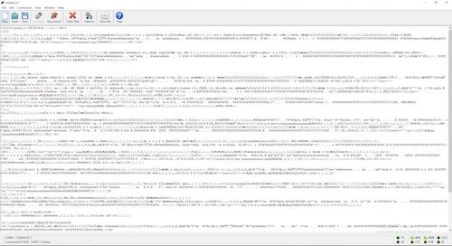
Dr. Harris said that we were interested in seeing what was being said to the camera when these cases were commanded. This way, we could communicate to the camera and tell it to do certain things without having to use the Host application. Dr. Harris had [this] software that he opened side by side with the Host application. We set the image to a BMP and saw that the command 01 was spit out that the camera reacted to. We then clicked “Capture” on the Host app, and the command 00 was written, prompting the camera to take the image. These two commands are the ones that we used to communicate with the camera from then on. When the camera captured the image, a bunch of gibberish was printed out into the program, showing that the image was being captured through the serial port. The issue was, this was gibberish and not in a recognizable format for other programs to open the image.
We then tried to use my Mac terminal to create a bitmap image while the camera was connected to my serial port, but Preview would not open the file because of the format. We decided to switch over to one of my lab’s PCs. Dr. Harris had another software we could use to receieve and record the characters that were being printed by the camera that was the image data. I downloaded CoolTerm onto the PC. I created a new file, connected the camera to the PC via the serial port by clicking Connect. Once I saw the
"ACK CMD ArduCAM Start! END"
"ACK CMD SPI interface OK. END"
"ACK CMD OV2640 detected. END"
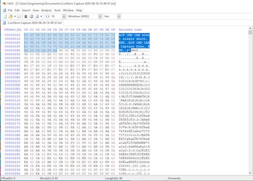
I knew the camera was connected. I then clicked Connection -> Capture to Text/Binary File -> Start to record what would be in the .txt file we would create. I entered 1, then 0, and watched the bitmap image data come in. I then clicked Connection -> Capture to Text/Binary File -> Stop to stop the “recording” and save the file. Once this binary file was created, Dr. Harris had another program that I downloaded on the PC called HXD that would allow us to view the bitmap data in hex. Being able to view and edit the raw image data was imperative because we could see exactly what was specifiying the image’s format.
The first thing that we needed to do what get rid of the BMP header. The BMP header is used to identify the file, but it was what was inhibiting the other programs from opening the image. As you can see, I selected and deleted everything up until the “B”:
After we did this and re-saved the image, I was able to open and view the image on my PC. From there, we needed to get the image from the original size, 320x240, and produce a smaller one from that image that was the size of my frame, 12x12. Dr. Harris found this link that broke down BMP images and how to understand and edit them. The most important part of this link was this image, which took apart a hex file and identified what everything meant.
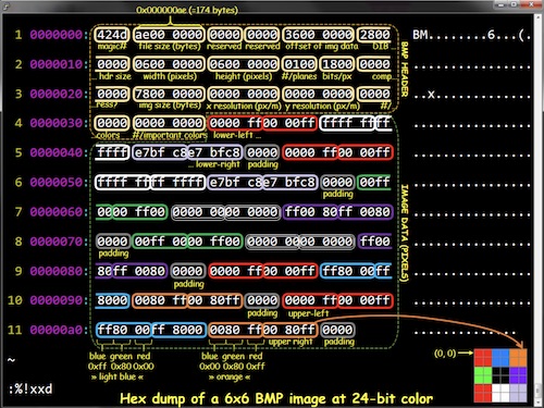
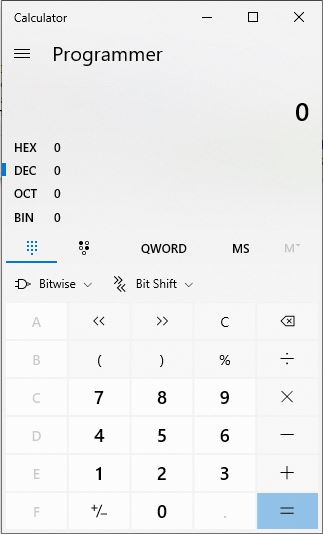
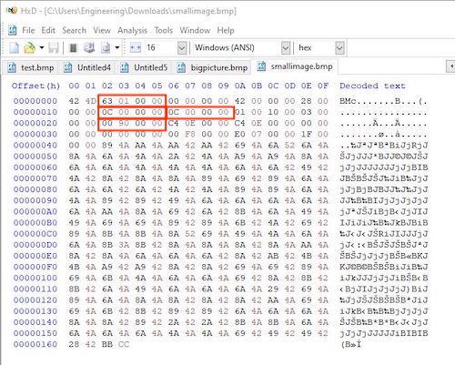
This allowed us to look at the hex file of the larger image and begin editing it so we could create a smaller image. The first step was changing the file size. As you can see, without the header, the size of the file is 00000163. Becuase the way it is written as 3 bytes, the formatting is super weird. It is written as the smallest byte -> to the middle byte -> to the largest byte. Basically, the file size is 163 bytes, so we wrote it as 63 01 00 00. Next was the width and height of the image. This we knew was the size of my frame, 12x12. I used the Windows calculator in Programming mode to calculate what 12 in dec was in hex. It was C, or as we wrote it, 0C. I filled in the correct spots for this dimension. The final change was changing the image size. This we knew would be 144 pixels. I put 144 in dec and the calculator said that that was 90 in hex. I also made this edit. You can see the changes I made in the screenshot below.
I saved the file and attempted to open the image. It worked! The image did not turn out like we thought:
Original:
From here, the question was: where are the 144 pixels coming from from the original image? Dr. Harris and I hypothesized that they were being taken from the top left corner of the image. This just made sense. However, given the dark image, we could not be sure. Dr. Harris formulated a test to figure out where the 12x12 grid was using the edited ArduCAM_Mini_2MP_Plus_functions code. The plan was to use the ArduCam to capture two images: one 320x240 image and one 12x12 image from the original 320x240. The large image would have the corner marked with a bright, noticeable color to tell where the 12x12 image was being taken from. Meanwhile, the 12x12 image would be normal. In order to carry out this plan, we began by creating another constant character for the bitmap header of the small image:
const char smallbmp_header[BMPIMAGEOFFSET] PROGMEM =
{
  0x42, 0x4D, 0x63, 0x01, 0x00, 0x00, 0x00, 0x00, 0x00, 0x00, 0x42, 0x00, 0x00, 0x00, 0x28, 0x00,
  0x00, 0x00, 0x0C, 0x00, 0x00, 0x00, 0x0C, 0x00, 0x00, 0x00, 0x01, 0x00, 0x10, 0x00, 0x03, 0x00,
  0x00, 0x00, 0x00, 0x90, 0x00, 0x00, 0xC4, 0x0E, 0x00, 0x00, 0xC4, 0x0E, 0x00, 0x00, 0x00, 0x00,
  0x00, 0x00, 0x00, 0x00, 0x00, 0x00, 0x00, 0xF8, 0x00, 0x00, 0xE0, 0x07, 0x00, 0x00, 0x1F, 0x00,
  0x00, 0x00
};
We implemented the changes from the hex we edited to take the previous 12x12 image (i.e. the byte and image size, the width, and height). I renamed the previous const char bigbmp_header. We then created another character: char smBMP[288];. This was the array of the small bitmap image, the value of which we got from multiplying 12x12x2 because there were 2 bytes.
The ArduCam code also has several differents modes, although we were not really sure what they did. We did know that we were using mode 3, so this section is where we went to add some more statements. Mode 3 used the characters VH and VL, which is what we were using in the previous time lapse code. These characters were what were written in the serial monitor to show the bitmap image data. There were also integers that were introduced, i and j, that represented the width and height of the image.
char VH, VL;
    int i = 0, j = 0;
    for (i = 0; i < 240; i++)
    {
      for (j = 0; j < 320; j++)
      {
        VH = SPI.transfer(0x00);;
        VL = SPI.transfer(0x00);;
In order to edit this large image and make the corner of it a bright color, we needed to find out the formula or algorithm of the small square. You can see the diagram on the bottom of the sheet we drew to visualize it:
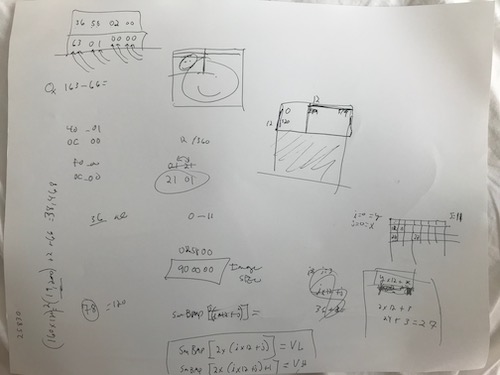
Each time you go down a row, you add 12. In order to go over a column, you add however many you are going over. Therefore, the formula was 12(row number) + (column number). Becuase i=row number and j=column number, I wrote this formula as (12*i)+j. In order to implement it in the code, we added an if statement that used the formula to write VH and VL as the small array. We decided on neon green as the color, using this RGB565 color picker to get the hex format for neon green:
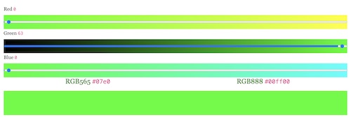
This color in RBG565 format is #07e0, and Dr. Harris explained to me that the VL = E0 and the VH = 07. We stored these characters into the small bitmap array. Here is this section of the code:
char VH, VL;
    int i = 0, j = 0;
    for (i = 0; i < 240; i++)
    {
      for (j = 0; j < 320; j++)
      {
        VH = SPI.transfer(0x00);;
        VL = SPI.transfer(0x00);;

       if(j<12 && i<12) {
        smBMP[2*((12*i)+j)] = VL;
        smBMP[2*((12*i)+j)+1] = VH;
        //store into smallbmp ARRAY
        VL = 0xE0;
        VH = 0x07;
        }

        Serial.write(VL);
        delayMicroseconds(12);
        Serial.write(VH);
        delayMicroseconds(12);
      }
    }
    Serial.write(0xBB);
    Serial.write(0xCC);
After creating the large image with the 12x12 neon green corner, the next step was creating the small image. We introduced integer k for the small image, creating a for loop that incremented k by one up until the size of the array. We then wrote this array to the serial monitor and added padding:
Serial.println("Here's the small image");
//   print smallBMP header
for (temp = 0; temp < BMPIMAGEOFFSET; temp++)
    {
      Serial.write(pgm_read_byte(&smallbmp_header[temp]));
    }
    for(int k = 0; k<288; k++){

      //    serial.write smallarray + padding
        Serial.write(smBMP[k]);

    }
     Serial.write(0xBB); //padding
    Serial.write(0xCC); //padding
I uploaded this sketch to the camera and opened CoolTerm to receive the image data. I copied the data and pasted it into HXD. I first deleted the small image data from the bottom (which was separated by our “here’s the small image” message) and pasted it into a new document. I then deleted the BMP headers from both the small and big images and saved them at bitmap images. I attempted to open them and the images showed up! You can see that the first image is the big image, as it has the neon green corner. We were surprised that the 12x12 frame actually came from the bottom left corner, as opposed to the top left as we had hypothesized. The next image is the small image, that fits into the big one like a puzzle piece.
You can download the code for this step here.
Averaging the Pixels
I then attempted to display both of the compressed bitmap images onto my neopixels using an LCD converter and the code I had used to display the PacMan ghosts. Because I did this at home adn only had access to my Mac, I downloaded a different LCD converter here. I selected the test.bmp image first, used the ST7735 16 bit option, then clicked Generate C Code.
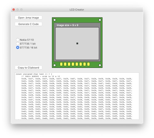
As you can see, the C code that was generated was in a different format as the HTML format I had used previously. Still, I pasted these values into my code and uploaded the sketch. Here’s how the neopixels lit up:
I repeated this process with the small bitmap image that had been created from the large one:
The next step was converting the bitmap from RGB565 to RGB888. This was because my neopixels ran on RGB888 given the code I had used previously to display the bitmap images. I attempted to upload a bitmap image using 16 bits as opposed to 24, but the image was not displayed. I realized that this was why the two images above were not displayed correctly. This confirmed that the conversion had to be made.
In addition to converting to RBG888, I needed to take the average of the bits in each 20x20 frame that made up the original 320x240 image so that the colors would be simplified for the smaller image. Dr. Harris broke down the steps that we would need to take to do this:
- Create a structure to hold all the RGB data as shown in this link
typedef struct __attribute__((__packed__)){
unsigned char blue;
unsigned char green;
unsigned char red;
} PIXELS;
-
Create a new global 2D array for the PIXELS of the large image before the Setup() function:
struct bigPIXELS [240] [320]; -
Convert RGB565 to RGB888 as shown in this post from Dr. Harris’s own blog. (!!! How cool is he)
-
Do the averaging.
I first created the structure, then created two 2D arrays: one big and one small. The big one was 320x240, the size of the image, while the smaller one was 12x16–the size we decided it would be easier to scale the image to (dividing by 20). I then read Dr. Harris’s post about the RGB conversions. He described the process of using logic operations and bit shifting to convert each pixel, followed by scaling each individual color from 5-bits to 8-bits. For this step, I inserted this code into my sketch (a copy of the previous code):
bigPIXELS [i][j].blue =    ( VL & 0b00011111 ) ;
bigPIXELS [i][j].red =   ((VH & 0b11111000) >> 3);
bigPIXELS [i][j].green =  (VL >> 5) | (VH << 3); //Shift lower 3 bits in VL to the decimal point, and shift the upper 3-bits in VH to their correct positions.

bigPIXELS[i][j].blue =  map(bigPIXELS[i][j].blue, 0, 0b11111, 0, 0b11111111); //blue was 5-bits
bigPIXELS[i][j].red=  map(bigPIXELS[i][j].red, 0, 0b11111, 0, 0b11111111); //red was 5-bits
bigPIXELS[i][j].green =  map(bigPIXELS[i][j].green, 0, 0b111111, 0, 0b11111111); //Remember that green has 6 pixels to begin with
The last step was the averaging. I first introduced three variables, and you can see Dr. Harris added a comment to describe why they needed to be long datatypes. These variables were the averages of each color. Then variables m & n were introduced for the size of the small image. Variables p & q were additionally introduced to get the averages of each 20x20 block of pixels. The data of each color were then added together and divided to get the average, that would then be stored into the small array.
//Averaging code:
long avgRed = 0; //we need a long datatype since we are adding 400 values and the result can be too big for an integer.
long avgGreen = 0;
long avgBlue = 0;
for (int m=0; m<12; m++){ // Our small picture has a size of 12 rows and 16 columns
   for (int n=0; n<16; n++){
     for (int p=m*20; p<20; p++){
       for (int q=n*20; q<20; q++){
        //averaging code goes here
        avgRed += bigPIXELS[p][q].red; //Add up all 400 values of red
        avgGreen += bigPIXELS[p][q].green;
        avgBlue += bigPIXELS[p][q].blue;
          }//end for q
      }//end for p

//Store this pixel into the small image
smallPIXELS[m][n].red = avgRed / 400;
smallPIXELS[m][n].green = avgGreen / 400;
smallPIXELS[m][n].blue= avgBlue / 400;

System.print( smallPIXELS[m][n].red);
System.print( smallPIXELS[m][n].green);
System.print( smallPIXELS[m][n].blue);
   }//end for n
}//end for m
I then had to fiddle around with the code a bit to get it to compile. One of the errors I recieved was that my big pixels array was too large. I decreased the numbers slightly until I reached values that did not prompt me with this error. After fixing some other errors, the code was almost able to compile. Then, I was hit with the error: there was not enough dynamic storage on the Arduino Uno for my sketch to be able to be run. In fact, even with a downgraded big array of 100x100 and a small array of 10x10, there was not nearly enough storage. Finally, I was able to compile the code–but only with a large array of 32x24, only twice the size of my small array, 16x12.
Dr. Harris had foreshadowed this problem. The Arduino Mega would be able to handle the values I initially wanted, but we did not have the chip that would allow me to make the board myself, as with the satshakit. The reason so much memory was necessary for this step was because a big image was being written, the values of each color was being summed and averaged, and a small image was being written from this. Dr. Harris proposed that I use another board that had more storage, such as an ESP. I downloaded the boards on Arduino for the ESP boards so that I could see if my code would compile with the larger array. I selected the ESP8266 Generic Module because we actually had those boards in the lab. The code compiled with a large array of 160x120. Dr. Harris advised that I try uploading the strandtest neopixel code to the ESP first, just to see if it would work. This ended up being a good plan, because the neopixels did not light up how they were supposed to. These particular boards are pretty cheap and rather unreliable, so despite their increased amount of memory, I decided that that probably was not the route I should take. Dr. Harris suggested one way we could decrease the memory needed. Instead of averaging all the RGB values, the mirror would be monochrome and only display blue lights. I’m pretty sure this is what SuperMakeSomething did for his own mirror, so I agreed with this idea.
To work around the Arduino’s memory shortage, Dr. Harris found a link to a method someone had developed to average the RGB values while still in 565 mode, which fortunately would save memory on the Arduino. We added several unsigned integers before the setup and edited the original code as our data had two separate bytes, VH and VL, while his had one.
uint16_t hicolor_avg( uint16_t a, char VHinput, char VLinput) {
uint16_t nextPixel = ( VHinput );
nextPixel = (nextPixel << 8) | ( VLinput & 0b0000000011111111);
const uint16_t s = nextPixel ^ a;
  return ((s & 0xF7DEU) >> 1) + ( nextPixel & a) + (s & 0x0821U);
}
We then introduced another unsigned int along with two for-loops that included the bit-shifted and combined VH and VL variables.
uint16_t pixelValue = 0
for(int i=0;i<320 i++){
for int j=0; j<240; j++){
if (i==0&&j==0)
{
pixelValue = ( VH  << 8) | (VL& 0b0000000011111111);
}
pixelValue = hicolor_avg ( pixelValue, VH, VL);
}//end j
}//end i
Basically, the pixel value was the average of the value of the pixels at 0 and the the high and low bit values. Dr. Harris proposed a way to tweak this a bit, providing me with this format that I wrote into the code:
This addition would restate the way that the data would be read into the small bitmap image. The beginning two for-loops would specify that the small bitmap would be 12x16, while the next two for-loops would detail how the pixel averaging for each 20x20 block from the original large image would work. Each pixel would be averaged with the one next to it, and so on. However, the first pixel could not average with the pixel to its right (because there was nothing there so it would average with 0, throwing off the color), so instead the if statement stated that it would average with itself so that the color would be the same. Given these conditions, the variable that was the average of the pixels (nextPixel) would be written to the small bitmap data. We also added two if statements that specified that the data would only be written if n< 16 and m< 12. Lastly, we wrote the small bitmap data to the serial port so that we would be able to see the bitmap image.
for(m=0, m<12, m++) {
  for(n=0, n<16, n++) {
  uint16_t nextPixel = 0;
    for(p=0, n<20, n++) {
      for(q=0, q<20, q++) {
      if(p=0; q=0) {
      nextPixel = ((VH << 8)|VL);
      }//if p,q
      }//end of q
    }//end of p
  if(m<12; n<16) {
  small[m][n] = nextPixel
    }//if m,n
  }//end of n
}//end of m
Serial.print(small);
The issue we began running into was the image data we were receiving from the camera through CoolTerm. Despite removing the header in HXD like we had done previously, the bitmap image would not display. Dr. Harris took to playing around with the integers and characters to get them to display in the serial monitor to see if the functions we desired were being carried out. This is how we found that the averaging was not working properly, along with with bitshifting that we had to do with the low and high values. Clearly, something was just not working quite right on this front. Consequently, we disucussed a change of plan so that we could make it easier on ourselves to convert and average everything correctly without having to worry about memory and whatnot. This plan involved streaming the big image, all 320x240 pixels, to the app Processing that I used in week 12. In Processing, we would then convert each pixel from RGB565 to RGB888, and then we would be able to easily average the newly formatted values. These values would be sent out the serial port to the Arduino, which would display the values on the neopixels.
Before changing tracks, we decided to revisit one of our earlier ideas: to take one pixel from each 20x20 group of pixels from the large image, whether it be the top left pixel or the middle pixel, and use them to create the smaller image. We decided to write a new formula to take a pixel from the top left corner. To do this, we drew a diagram to help visualize it. We used two of the variables we were previously using, i (y-axis) and j (x-axis). We went ahead and made the 320x240 size of the image to 240x240 so the ratio would be correct for my frame. At first, we attempted to use the if mods I had written earlier: if(i%20==0 && j%20==0), then the image data would be written to the bitmap. We then used an excel spreadsheet to write the formula and ensure that each point was translating to the correct point for the smaller image (pixels 0-143). For some reason, the if mod was not working and was not in fact getting the multiples of 20. Although it was tedious, we manually wrote out each multiple of 20 from 0-220:
if(i==0 ||i ==20 ||i==40||i==60||i==80||i==100||i==120||i==140||i==160||i==180||i==200||i==220){
  if(j==0 ||j ==20 ||j==40||j==60||j==80||j==100||j==120||j==140||j==160||j==180||j==200||j==220){
        int offsetIndex = (j/20)+(i/20)+((i/20)*11);
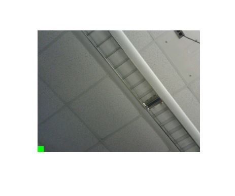
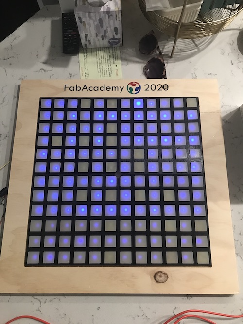
I commented out the small 12x12 green pixel so instead a neon green one would be written every 20 pixels. I then uploaded the sketch. I took a picture with the camera and used CoolTerm to separate the large and small image. Here is how the large image turned out:
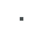
You can see that there is a neon green pixel every 20 pixels to create the 12x12 small image. The edge of the image does not have any pixels because it is chopped off to fit my frame. When it came to the small image, however, it did not look like the original:
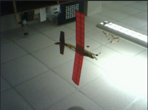
The colors did not match up to what they were supposed to be on the large image. The code for the large image was correct, but there was something that needed to fixed for the small image. insert what the reason was here. i think it was the vh and vl but im not exactly sure so ask dr. harris After making these alterations, we reploaded the sketch and took another picture with some contrasting colors that would be very visible. For some reason, holding the camera right side up how I thought it should be held turns the image upside down, so I will have to mount the camera upside down on my final project. Here is the large image:
Here is the small image. It worked! We were able to resize the original 320x240 image to the size of my frame, 12x12. Though it is obviously pixelated and not the best resolution, you can still see what it is from the original image. This was a huge milestone, especially after several days working on this step.
I then used my LCD converter to get the HTML color values of the image to display to it to the neopixels. The image generated this array, which I plugged into the code I had used previously to upload bitmap images.
0x203038, 0x588878, 0x487878, 0x688460, 0x688060, 0x688060, 0xc0fce0, 0xb8fcd8, 0xb07860, 0xb87060, 0xd08470, 0xe09080,
0x586c58, 0xa0d8c0, 0xa0dcc8, 0xa0e0c0, 0xa0dcc0, 0xa8e0c0, 0xa8d8c0, 0xa0d0b8, 0x985848, 0xb06450, 0xc87468, 0xe08c78,
0x90c4b0, 0x88bcb0, 0x88c0a8, 0x90c0a8, 0x98ccb8, 0xa8e0c0, 0x70a080, 0x181c18, 0x985840, 0xb06050, 0xc87460, 0xd88868,
0x789c90, 0x285050, 0x486c60, 0x608470, 0x103020, 0x103028, 0x102820, 0x102c20, 0xa05440, 0xb86450, 0xc87460, 0xd88068,
0x204038, 0x102020, 0x285c50, 0x102020, 0x203830, 0x203c30, 0x284438, 0x284830, 0xa85048, 0xb86450, 0xc87058, 0xd87c60,
0x183040, 0x182828, 0x102028, 0x101c18, 0x101818, 0x102820, 0x182420, 0x182018, 0xa85048, 0xb86450, 0xc07058, 0xd07860,
0xf8fcf8, 0xf8fcf8, 0xf8fcf8, 0xf8fcf8, 0x102428, 0x102420, 0x102820, 0x102020, 0xa05440, 0xb06058, 0xc06c50, 0xd07058,
0xf8fcf8, 0xf8fcf8, 0xf8fcf8, 0xf8fcf8, 0x182c28, 0x102420, 0x102418, 0x102018, 0xa05448, 0xa86050, 0xc06858, 0xc87058,
0xf8fcf8, 0xf8fcf8, 0xf0fcf8, 0xc8fcf8, 0x182830, 0x102818, 0x182420, 0x181c18, 0xa05448, 0xb05c48, 0xb86058, 0xc06c58,
0xd8fcf8, 0xd8fcf8, 0xb8f8f8, 0xc0fcf8, 0x102420, 0x102018, 0x182020, 0x201810, 0x984c48, 0xa85450, 0xb05c50, 0xb86458,
0xe0fcf8, 0xd0fcf8, 0xd0fcf8, 0xb8fcf8, 0x101c28, 0x102020, 0x102020, 0x482428, 0x984448, 0xa05040, 0xb05840, 0xb06048,
0xc8fcf8, 0xc0fcf8, 0xc8fcf8, 0xb8f4f8, 0x102020, 0x182420, 0x182020, 0x785058, 0x984038, 0x985038, 0xa85448, 0xb05c50
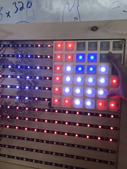
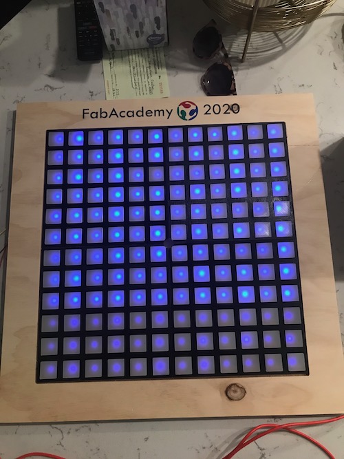
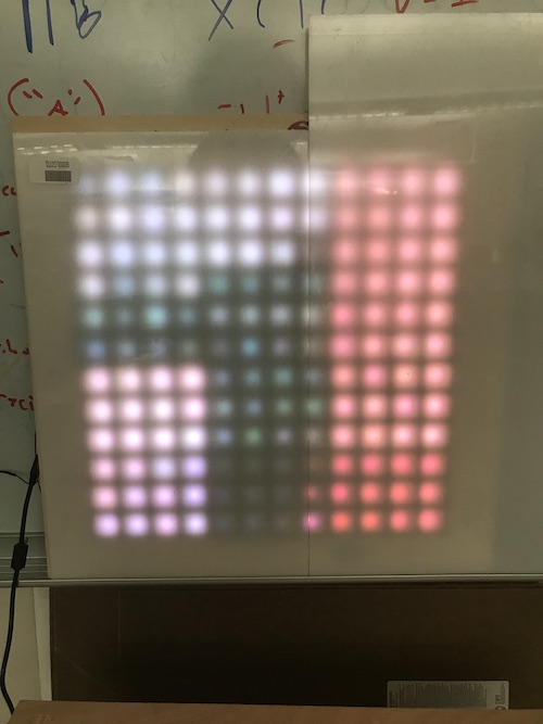
It worked! Here are my neopixels lit up. Dr. Harris also found some white translucent acrylic to diffuse the light a bit more, because I turned up the brightness of the neopixels and the EcoFlex casts were not diffusing as much as I had wanted them to. Still, you can kind of make out the compressed image!
Here is the .txt file from Coolterm that contains the ASCII/hex data for these images. Here is the code for this step.
Converting RGB565 to RGB888
Once we had the averaging working, the next step was converting the RGB values. The previous segment of code we had inserted was messing up the functionality and outcome of the pictures, so we needed a different way to get to RGB888. Dr. Harris found this person who had converted the color values in Processing. We first created two arrays based off of his:
byte combined[288];
int rgbint[3];
The first one being the total amount of bytes for my array, the second one being the rgb values. We then used the components of his void wordToRGB(byte[] combined){ section in the code. We created an if statement that described that if our integer k was a multiple of 2, the following conditions would be carried out. The reasoning behind this was that there were 288 bytes in the array, so each pixel was represented by every 2 chars. The pixel was stored as VL, VH when it was combined into one object, ultimately giving us the 144 pixels total for my frame. Then came the conversions. This involved the rbgint array and bitshifting. Afterwards, we wrote each color to serial.
 //If even index (k= even)
    if (k%2 ==0){
      int c = (smBMP[k] << 8) | (smBMP[k+1] & 0xFF);
  //RGB565
  rgbint[0] = (c >> (6+5)) & 0x01F;
  rgbint[1] = (c >> 5) & 0x03F;
  rgbint[2] = (c) & 0x01F;

  //RGB888 - amplify
  rgbint[0] <<= 3;
  rgbint[1] <<= 2;
  rgbint[2] <<= 3;

  Serial.write(rgbint[0]);
  Serial.write(rgbint[1]);
  Serial.write(rgbint[2]);
    }
After uploading the sketch and receiving the image data through CoolTerm, the hex data was supposed to be the RGB values that the neopixels could read and display. The only thing was, they were separated in groups of two and were missing the 0x at the beginning. I copied and pasted the data into Arduino and manually added the 0x to the beginning of each group of 3 pairs. I went back through and deleted the spaces between the pairs so that the format was 0x000000,. We had commented out the header, so I did not need to worry about removing that. This was tedious and took longer than I’d care to admit, let me tell you:
0xE0E810, 0xE80C58, 0xB09470, 0x50D878, 0x70D8B8, 0x88ACE0, 0x40E858, 0x20E898, 0xF0F8F8, 0x80EC18, 0xC82C18, 0xE80C58,
0x60A488, 0xE0E810, 0x00A858, 0xE0C850, 0xA0E4D0, 0xC084D0, 0xA0E810, 0xE0A850, 0xC848D8, 0x684CE0, 0x40C898, 0xC80C58,
0xA0C488, 0x60C810, 0xC0A810, 0xA0C810, 0xA08810, 0xA0A490, 0x80A810, 0x00A4D8, 0xA808D8, 0x60E898, 0x00A858, 0x080C20,
0x806408, 0x80E4D0, 0xA0C850, 0x80A4D0, 0x808490, 0x60C490, 0xA0A4D0, 0xC0C810, 0xC0E8D8, 0x60C858, 0x00C898, 0x60C858,
0xA04040, 0xC0A4D0, 0xE08850, 0x40A810, 0x60A450, 0x808490, 0x80A4D0, 0xA0C810, 0xC82C18, 0x20A818, 0xA0C810, 0x00C858,
0x602040, 0x60E810, 0xC0A850, 0x60A4D0, 0x606490, 0x608490, 0x8064D0, 0x80A4D0, 0xC80C18, 0xC0C850, 0xC0A4D0, 0x20C898,
0xC04000, 0x408490, 0x00A858, 0x60C810, 0x60A490, 0x40A450, 0x60A4D0, 0xA084D0, 0xA0EC18, 0xE0C810, 0x60C4D0, 0x00E818,
0x800040, 0xA04408, 0x20A818, 0x806850, 0x608810, 0x40A490, 0x60C4D0, 0x80C810, 0x80E8D8, 0x582860, 0x70E820, 0x70C860,
0x402040, 0xA080C8, 0x00A858, 0x6040C8, 0xA064C8, 0xA0EC18, 0xE80C58, 0x80A810, 0x480898, 0x98EC28, 0x582820, 0xB868A0,
0xA04080, 0x804488, 0x20E898, 0x0818E0, 0x48BCE8, 0xB03CF0, 0x907CF8, 0x080C18, 0x20EC18, 0x78E8A8, 0x30A8A0, 0x5808E0,
0x606080, 0x806448, 0xA0C898, 0xA0F898, 0x48BCE8, 0xF03CF0, 0x707CF8, 0xA0E890, 0x80C8D8, 0x78E8A8, 0xF8EC68, 0xD8EC68,
0xA06080, 0xC04488, 0x284C60, 0x881458, 0x28BCE8, 0xF05CF0, 0x707CF8, 0x60E8D8, 0xA0EC58, 0x78E8E8, 0x98EC28, 0x38E8A8
Once it was done, I used the code I’d been using to upload to the neopixels. The result… not the image, that’s for sure. The neopixels displayed random colors.
I went into Processing and pasted the person’s code I had been using for the RGB conversion. I put the 12x12 image I had been able to upload successfully into the sketch folder and played the sketch. The basis of the sketch was that you could put your mouse over a color and it would show you the original color and than the converted color. I hovered my mouse over different pixels of the image and compared them to the code I has uploaded to the neopixels when it worked. This was to double check the colors and formatting. As far as I could tell, all the colors were correct. The ones being read on the Processing sketch were the ones that I had converted using the LCD converter and uploaded to the LEDs.
We decided to revert back to the color conversion method from Dr. Harris’s blog. He noticed a bug in the original code so this is the fixed code I added:
typedef struct {
  unsigned char blue;
  unsigned char green;
  unsigned char red;
} PIXELS;

PIXELS bigPIXELS [12][12]; //the resulting RGB888 picture pixels are stored here
byte smBMP[288];// The original 320 x 240 image stored here in RGB565 format

bigPIXELS [i][j].blue = ( VL & 0b00011111 ) ; //0x1F

bigPIXELS [i][j].red = ((VH & 0b11111000) >> 3); //0xF8

VL&= 0b11100000 ;
VH &= 0b00000111; //0x07

bigPIXELS [i][j].green =  (uint8_t(VL) >> 5) | (VH << 3); //Shift lower 3 bits in VL to the decimal point, and shift the upper 3-bits in VH to their correct positions.

bigPIXELS[i][j].blue = bigPIXELS[i][j].blue << 3;//blue and red were 5-bits

bigPIXELS[i][j].red=  bigPIXELS[i][j].red<<3;

bigPIXELS[i][j].green =  bigPIXELS[i][j].green <<2;//Remember that green has 6 pixels to begin with so it only shifts 2 places

Serial.write(bigPIXELS [i][j].red);
Serial.write(bigPIXELS [i][j].green);
Serial.write(bigPIXELS [i][j].blue);
I uploaded the sketch and took a picture to get the data from CoolTerm. Upon just seeing the raw data, it looked like the RGB values were converted and everything worked out fine. However, that’s not my luck. After pasting the values into my neopixel code and separating the groups of 3 pairs into 12 columns, the data ran out after 5 rows. I was not sure where the rest of the image data went. I asked Dr. Harris and he suggested I add in print statements to see the values of i, j, VH, and VL:
Serial.print("i="); //will print an "i=" characters and the following number value will be that value in ASCII so you should be able to actually read it
Serial.print(i/20); //divide by 20 so you'll get 12 values of I
Serial.print(" j="); //will print an "j=" characters and the following number value will be that value in ASCII so you should be able to actually read it
Serial.print(j/20); //divide by 20 so you'll get 12 values of J
Serial.print(" VL=");
Serial.write(VL); //this will print in hex, so look at the hex side of the code window to see the number value
Serial.print(" VH=");
Serial.write(VH); //this will print in hex, so look at the hex side of the code window to see the number value
I did this and found that everything was incrementing accordingly:
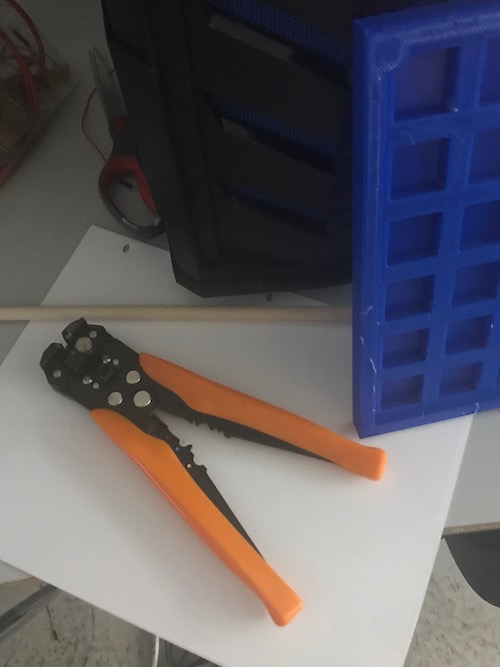
The i and j integers were going all the way up to 12, so the data was all accounted for. Dr. Harris looked at my code and pointed out that bigPIXELS [i][j] was actually supposed to be bigPIXELS [i/20][j/20]. This way, the 12x12 would be stored in the variable bigPIXELS. I went through and fixed this error and re-uploaded the code. I took a picture of some wire cutters on a piece of paper and my 3D print because they were brightly colored and would be easily spotted when displayed on the neopixels.
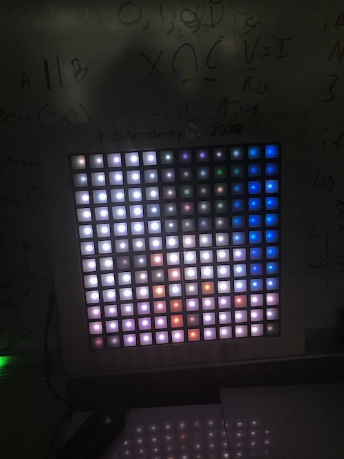
I still had to manually go through and add the prefixes to each group of numbers and delete the spaces. Finally, I uploaded the code to my neopixels. It worked! Because of my small frame, there is limited resolution. Still, the colors and general shapes are there.
Here is the code for this step.
Writing the Code Cont’d (Networking & Communications)
Connecting with the Neopixels
Now that the image was able to be compressed and converted, the final step was to get the image data ready for the neopixels and take pictures with the camera continuously so the mirror effect was established. This included adding the 0x prefix and deleting the spaces automatically and figuring out how to constantly send the data to the neopixels. At the same time, I was beginning to combine the camera and neopixel code. Immediately upon attempting to compile it, I got a ton of error messages that I didn’t really understand. It was then pointed out to me that both the neopixel library and the ArduCam’s library used SPI, which was what was prompting all the errors.
Dr. Harris sent me this link that described how to use multiple SPI devices on an Arduino. Ultimately, it was easier to have an Arduino controlling each of the components–one for the camera and one for the neopixels–but reading the article was still beneficial to learning about the topic. That being said, I decided to use my satshakits from week 14 to have communication between the camera and neopixels.
I began working on the neopixel code. Dr. Harris found a tutorial fromthis blog that was very similar to what I was doing. The code read data from serial and put it into a string. It also used the FastLED library, creating an array with the converted RGB values and editing the incoming String to be displayed. It also involved the use of Arduino’s serial.event example.
/* Arduino 256 RGB LEDs Matrix Animation Frame
 * Using WS2812 LED Strips
Created by Yvan / https://Brainy-Bits.com
This code is in the public domain...
You can: copy it, use it, modify it, share it or just plain ignore it!
Thx!
*/

String inputString = "";         // a String to hold incoming data
bool stringComplete = false;  // whether the string is complete

#include <avr/pgmspace.h>  // Needed to store stuff in Flash using PROGMEM
#include "FastLED.h"       // Fastled library to control the LEDs

// How many leds are connected?
#define NUM_LEDS 144

// Define the Data Pin
#define DATA_PIN 6  // Connected to the data pin of the first LED strip

// Define the array of leds
CRGB leds[NUM_LEDS];

// Create the array bRGB888 values
long image[144];


void setup() {
FastLED.addLeds<NEOPIXEL,DATA_PIN>(leds, NUM_LEDS);  // Init of the Fastled library
FastLED.setBrightness(15);

  // initialize serial:
  Serial.begin(9600);
  // reserve 450 bytes for the inputString:
  inputString.reserve(450);
}

void loop() {

 // print the string when a newline arrives:
  if (stringComplete) {

/*Combine the individual bytes into long integers
in a single array.
There should be 432 bytes on the serial string.
At the end, there's likely a lineFeed and Carriage Return,
so -2 off the length will get rid of these two bytes.

There should be 432 bytes of data and they are in the order
R0, G0, B0, R1, G1, B1, R2, G2, B2.

We need to combine the RGB values for each pixel into a single number.
This is stored into the array at the top, then that array is sent to the
neopixels in the second loop
*/
for(int i=0; i<inputString.length-2; i+=3){ //we want to start on the R value of each pixel, so we'll count by 3s

//  I'm going to divide i/3 which will give me the correct index for my 144-valued array of pixels in the final image.
  image[i/3]= inputString[i]<<16; //Bring in the red value and shift it to the correct position
  image[i/3] |= inputString[i+1] <<8; //Bring in the Green value and shift and OR it to the red one
  image[i/3] |= inputString[i+2]; // add the bnlue vlalue to the other values
  image[i/3] &= 0x00FFFFFF;  //This will get rid of the leading "1111" in the long datatype which otherwise messes things up.

}

FastLED.clear();
for(int i = 0; i < NUM_LEDS; i++) {
    leds[i] = image[i];  // Read from array and send to the neopixels
  }

FastLED.show();
delay(500);


/*
(Optional) Print string to make sure it's correct (debugging)
You'll have to do something funny here
YOu will have to wire up a second FTDI and only connect
the arduino's TX line and GND to this FTDI.
The arduino's RX line should be connected to the
camera-Arduino's TX line.

This way this arduino can recieve messages from the
camera-arduino
but if this one sends serial.print it will
appear on the computer terminal
*/
//Serial.println(inputString);


    // clear the string:
    inputString = "";
   stringComplete = false;


}//end if string complete

}//end loop


/*
  SerialEvent occurs whenever a new data comes in the hardware serial RX. This
  routine is run between each time loop() runs, so using delay inside loop can
  delay response. Multiple bytes of data may be available.
*/
void serialEvent() {
  while (Serial.available()) {
    // get the new byte:
    char inChar = (char)Serial.read();
    // add it to the inputString:
    inputString += inChar;
    // if the incoming character is a newline, set a flag so the main loop can
    // do something about it:
    if (inChar == '\n') {
      stringComplete = true;
    }
  }
}
This was the basic first iteration of this code. The next iteration added several specific parts that were necessary for the camera and neopixels to communicate. I needed the camera to continuously take a picture so it was almost streaming, giving the neopixels the mirror effect. To do this, we added
Serial.write(0x30);
Serial.write(0x31);
to the setup and loop. Initially, we thought we should use 0x00 and 0x01 because we had been typing those commands into serial. But it turns out the camera responded to the actual case numbers from the original code, so I used 0x30 and 0x31 instead. Next, Dr. Harris advised that I add a button to my neopixel Arduino as a way to clear the data and reset the neopixels. I connected a breadboard and added a button on pin 4.
/* Arduino 256 RGB LEDs Matrix Animation Frame
 * Using WS2812 LED Strips
Created by Yvan / https://Brainy-Bits.com
This code is in the public domain...
You can: copy it, use it, modify it, share it or just plain ignore it!
Thx!
*/

String inputString = "";         // a String to hold incoming data
bool stringComplete = false;  // whether the string is complete

#include <avr/pgmspace.h>  // Needed to store stuff in Flash using PROGMEM
#include "FastLED.h"       // Fastled library to control the LEDs

// How many leds are connected?
#define NUM_LEDS 144

// Define the Data Pin
#define DATA_PIN 6  // Connected to the data pin of the first LED strip

// Define the array of leds
CRGB leds[NUM_LEDS];


void setup() {
FastLED.addLeds<NEOPIXEL,DATA_PIN>(leds, NUM_LEDS);  // Init of the Fastled library
FastLED.setBrightness(25);

//put a button on pin 4 with an internal pullup
pinMode(4, INPUT);
digitalWrite(4, HIGH);


  // initialize serial:
  Serial.begin(115200);
  // reserve 450 bytes for the inputString:
  inputString.reserve(450);

  delay(7000); //delay enough to allow camera to come online

  //send command to take a picture.
Serial.write(0x31);
Serial.write(0x30);
}

void loop() {


if(digitalRead(4)==LOW){ //if button is pushed
    FastLED.clear(); //clear neopixel data

    // clear the string:
    inputString = "";
   stringComplete = false;

//Ask for new picture to be taken
Serial.write(0x31);
Serial.write(0x30);

}//end button pushed

 // print the string when a newline arrives:
  if (stringComplete) {

/*Combine the individual bytes into long integers
in a single array.
There should be 432 bytes on the serial string.
At the end, there's likely a lineFeed and Carriage Return,
so -2 off the length will get rid of these two bytes.

There should be 432 bytes of data and they are in the order
R0, G0, B0, R1, G1, B1, R2, G2, B2.

We need to combine the RGB values for each pixel into a single number.
This is stored into the array at the top, then that array is sent to the
neopixels in the second loop
*/
for(int i=0; i<inputString.length()-2; i+=3){ //we want to start on the R value of each pixel, so we'll count by 3s

//  I'm going to divide i/3 which will give me the correct index for my 144-valued array of pixels in the final image.
  leds[i/3].red = inputString[i]; //Bring in the red value
  leds[i/3].blue = inputString[i+1]; //Bring in the Green value
  leds[i/3].green = inputString[i+2]; // add the blue
}

FastLED.show();
delay(500);

/*
(Optional) Print string to make sure it's correct (debugging)
You'll have to do something funny here
YOu will have to wire up a second FTDI and only connect
the arduino's TX line and GND to this FTDI.
The arduino's RX line should be connected to the
camera-Arduino's TX line.

This way this arduino can recieve messages from the
camera-arduino
but if this one sends serial.print it will
appear on the computer terminal
*/
//Serial.println(inputString);

    // clear the string:
    inputString = "";
   stringComplete = false;
FastLED.clear();
//Ask for another picture to be taken
Serial.write(0x31);
Serial.write(0x30);
}//end if string complete

}//end loop


/*
  SerialEvent occurs whenever a new data comes in the hardware serial RX. This
  routine is run between each time loop() runs, so using delay inside loop can
  delay response. Multiple bytes of data may be available.
*/
void serialEvent() {
  while (Serial.available()) {
    // get the new byte:
    char inChar = (char)Serial.read();
    // add it to the inputString:
    inputString += inChar;
    // if the incoming character is a newline, set a flag so the main loop can
    // do something about it:
    if (inChar == '\n') {
      stringComplete = true;
    }
  }
}
I uploaded the new code and set up my Arduinos. I connected TX and RX of the Arduinos (TX going to RX) and the GNDs. One Arduino had the camera still attached to it via all the necessary pins, while the other Arduino had the neopixels connected at D6 and GND and the button at D4 and GND. I connected one Arduino to the PC and the other to my laptop. I then opened the serial monitors on both. I saw that the Arduinos were communicating–the image data was shown on the camera’s serial monitor and 101010 was being repeated on the neopixels’ serial monitor. This was correct because that is what we sent to change the format from JPEG to BMP and request that the camera take a picture.
Not only were my neopixels not lighting up, the I was pretty sure there was something going on with the incoming data and what the neopixels were actually receiving. I first changed the format of the image data that was being written to serial in the camera code. I changed
Serial.write(bigPIXELS [i/20][j/20].red);
Serial.write(bigPIXELS [i/20][j/20].green);
Serial.write(bigPIXELS [i/20][j/20].blue);
to
Serial.print(bigPIXELS [i/20][j/20].red);
Serial.print(bigPIXELS [i/20][j/20].green);
Serial.print(bigPIXELS [i/20][j/20].blue);
so instead of getting a bunch of weird characters I got the RGB values from 0-255:


Dr. Harris linked me the Github for FastLED. I read through it and saw that I needed to change the format of the incoming data to CRGB(,,__). I added these into the camera code so this is what went to serial:
Serial.print("CRGB(");
Serial.print(bigPIXELS [i/20][j/20].red);
Serial.print(",");
Serial.print(bigPIXELS [i/20][j/20].green);
Serial.print(",");
Serial.print(bigPIXELS [i/20][j/20].blue);
Serial.print("),");
I then tried to figure out why the neopixels were not receiving this data exactly. I commented out the for-loop that divided the array i by 3 and additionally changed the if statement if (stringComplete) to if (stringComplete = true). I reuploaded the sketches. I saw that the incoming data was exactly what the camera was sending:
Still, my neopixels did not light up. I reuploaded one of my PacMan ghost bitmap images to check to make sure my neopixels still worked. It displayed, so they did work. I went back to the code to see if I could figure out what the issue was. Turns out I was not supposed to use 0-255 values, and the ASCII characters that came into the serial port were read as hex. I undid those changes and reuploaded the camera code. One of the issues Dr. Harris caught was that the neopixel code was waiting for a new line to make the stringComplete=true, so we added in a Serial.println(); at the end of where we wrote the RGB colors to serial. We also changed where we wrote the case numbers to serial to write “1” and “0”, just to make sure that the neopixel Arduino was correctly requesting the switch to BMP format and a picture. We uploaded the code and the neopixels lit up… except it was only the first 21 that did so. The neopixels were appearing to update color-wise, but only those first 21. We deduced that the Arduino could not read and display all 432 bytes of data that we were sending it.
From there, Dr. Harris had the idea that perhaps we should split up the data. We wrote an if mod for the camera code and then repeated everything in the neopixel code that occured for inputString. Instead, I created inputStrings 1-4:
String inputString1 = "";
String inputString2 = "";
String inputString3 = "";
String inputString4 = "";
We changed the reserve values for the bytes,
inputString1.reserve(110);
inputString2.reserve(110);
inputString3.reserve(110);
inputString4.reserve(110);
cleared the string,
inputString1 = "";
inputString2 = "";
inputString3 = "";
inputString4 = "";
stringComplete = false;
and created the corresponding for-loops while subtracting from the incremented amount in the arrays.
for (int i = 0; i < 108; i += 3) { //we want to start on the R value of each pixel, so we'll count by 3s

      //  I'm going to divide i/3 which will give me the correct index for my 144-valued array of pixels in the final image.
      leds[i / 3].r = inputString1[i]; //Bring in the red value
      leds[i / 3].g = inputString1[i + 1]; //Bring in the Green value
      leds[i / 3].b = inputString1[i + 2]; // add the blue
    }
for (int i = 0; i < 108; i += 3) { //we want to start on the R value of each pixel, so we'll count by 3s

      //  I'm going to divide i/3 which will give me the correct index for my 144-valued array of pixels in the final image.
      leds[i / 3].r = inputString2[i-109]; //Bring in the red value
      leds[i / 3].g = inputString2[i + 1-109]; //Bring in the Green value
      leds[i / 3].b = inputString2[i + 2-109]; // add the blue
    }
for (int i = 0; i < 108; i += 3) { //we want to start on the R value of each pixel, so we'll count by 3s

      //  I'm going to divide i/3 which will give me the correct index for my 144-valued array of pixels in the final image.
      leds[i / 3].r = inputString3[i-217]; //Bring in the red value
      leds[i / 3].g = inputString3[i + 1-217]; //Bring in the Green value
      leds[i / 3].b = inputString3[i + 2-217]; // add the blue
    }

for (int i = 0; i < 108; i += 3) { //we want to start on the R value of each pixel, so we'll count by 3s

      //  I'm going to divide i/3 which will give me the correct index for my 144-valued array of pixels in the final image.
      leds[i / 3].r = inputString4[i-325]; //Bring in the red value
      leds[i / 3].g = inputString4[i + 1-325]; //Bring in the Green value
      leds[i / 3].b = inputString4[i + 2-325]; // add the blue
    }
I specified the range of what would be added to inChar depending on which quarter of the grid it was:
if(numBytes < 108) {
      // add it to the inputString:
      inputString1 += inChar;
//            mySerial.println(inChar);

    }
   if(numBytes > 109 && numBytes < 216) {
      // add it to the inputString:
      inputString2 += inChar;
    }
    if(numBytes > 217 && numBytes < 324) {
      // add it to the inputString:
      inputString3 += inChar;
    }
    if(numBytes > 325 && numBytes < 432) {
      // add it to the inputString:
      inputString4 += inChar;
    }
Lastly, we added to the if statement that the number of bytes received had to be greater than 400 (ours was supposed to be 432) for the string to be finished.
if (inChar == '\n' && numBytes > 400) {
When we ran this code, only the first quarter (first 36 pixels) lit up. There was occasional image data coming in, but it was not updating like it was supposed to. Not to mention that 3/4 of the grid did not light up.
Dr. Harris found this guy who was able to receive any string up to 1024 bytes and echo it back over the serial. We played around with his code a bit but did not ultimately end up using it.
However, we did switch gears towards using software serial, which is where we ultimately found success. I had two FTDI chips hooked up to my Arduinos, one with 5V and GND connected (powering both Arduinos) and the other with GND and RX connected to D11 on the neopixel Arduino. This would allow us to see what data the neopixel Arduino was sending back to the camera Arduino.
With the SoftwareSerial mySerial(10,5); line, we defined which pins were RX and TX. Though I used pin 11 on the Arduino for TX, I changed it to pin 5 for the satshakit. pixelNum was the integer that we defined to be the array for the grid. We reserved 200 bytes for the array, just a bit more than 144, then set the baud rate and initilized the FastLED library as we had done previously.
One of the important parts of software serial is the mySerial port that was defined earlier. In the loop, we print the pixel number on the grid and then the incoming string to the neopixel satshakit’s serial port once it has finished coming in. Finally, the string is reset and the 1 and 0 are printed again to take a new picture. The void serialEvent is where the bytes are added to the string. Here is the code:
#include <SoftwareSerial.h>
#include <Arduino.h>
/*
  Serial Event example

  When new serial data arrives, this sketch adds it to a String.
  When a newline is received, the loop prints the string and clears it.

  A good test for this is to try it with a GPS receiver that sends out
  NMEA 0183 sentences.

  NOTE: The serialEvent() feature is not available on the Leonardo, Micro, or
  other ATmega32U4 based boards.

  created 9 May 2011
  by Tom Igoe

  This example code is in the public domain.

  http://www.arduino.cc/en/Tutorial/SerialEvent
*/
#include "FastLED.h"// Fastled library to control the LEDs

String inputString = "";         // a String to hold incoming data
bool stringComplete = false;  // whether the string is complete
SoftwareSerial mySerial(10,5);
// How many leds are connected?
#define NUM_LEDS 144

// Define the Data Pin
#define DATA_PIN 6  // Connected to the data pin of the first LED strip


// Define the array of leds
CRGB leds[NUM_LEDS];

int pixelNum=0;


void serialEvent();
void setup() {
  // initialize serial:
  Serial.begin(115200);
  // reserve 200 bytes for the inputString:
  inputString.reserve(200);

  mySerial.begin(115200);
  mySerial.println("Hello, world?");

  FastLED.addLeds<NEOPIXEL, DATA_PIN>(leds, NUM_LEDS); // Init of the Fastled library
  FastLED.setBrightness(45);

   Serial.print("1");//put camera in bitmap mode

     Serial.print("0");//get picture

}

void loop() {


  // print the string when a newline arrives:
  if (stringComplete) {
//    Serial.print("input=");
//    Serial.print(inputString);
 mySerial.print("pixel=");
    mySerial.print(pixelNum);
    leds[pixelNum].r=inputString[0];
    leds[pixelNum].g=inputString[1];
    leds[pixelNum].b=inputString[2];

        FastLED.show();

mySerial.print("RBG = ");
mySerial.print(leds[pixelNum].r);
mySerial.print(", ");
mySerial.print(leds[pixelNum].g);
mySerial.print(", ");
mySerial.print(leds[pixelNum].b);
mySerial.print("\n");
    // clear the string:
    inputString = "";
    stringComplete = false;
    pixelNum++;
  }
  if(pixelNum == NUM_LEDS){
    pixelNum=0; //reset to first LED
    Serial.print("1");//put camera in bitmap mode
    Serial.print("0");//get picture
  }
}

/*
  SerialEvent occurs whenever a new data comes in the hardware serial RX. This
  routine is run between each time loop() runs, so using delay inside loop can
  delay response. Multiple bytes of data may be available.
*/
void serialEvent() {
  while (Serial.available()) {
    // get the new byte:
    char inChar = (char)Serial.read();
    // add it to the inputString:
    inputString += inChar;
    // if the incoming character is a newline, set a flag so the main loop can
    // do something about it:
    if (inChar == '\n') {
      stringComplete = true;
    }
  }
}
We directly inserted the Software Serial and Serial.event example code. We created pixelNum to collect the RGB data into an array, which would be printed to serial preceding a new line. This code worked!! The camera was just pointed at the ceiling initially, so you can see the lights on the ceiling being displayed:
Some cons were the bad resolution and the camera’s auto-light features that adjusted the brightness of the neopixels according the how bright the light was that the camera was seeing. This made it a bit difficult to see the shapes and colors of what the camera was taking pictures of, but we played around with it a bit. One of my instructors, Dr. Taylor, had the idea to put the FabLab logo in front of the camera. He and Dr. Harris held the logo against a white background while I pointed the camera to try and get it positioned correctly to display the logo. You can see the colors and shape of the logo! The cool thing also is that when I was in engineering in seventh grade, I painted that very logo for our lab. Really coming full circle!
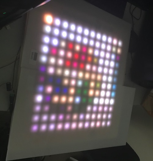
Now that I knew everything worked with Arduinos, I uploaded the codes to my satshakits. Both of them uploaded successfully and I hooked up everything accordingly. Here was my setup:
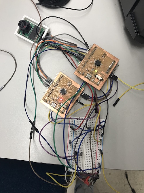
I then put the camera behind the backboard and plugged everything in:
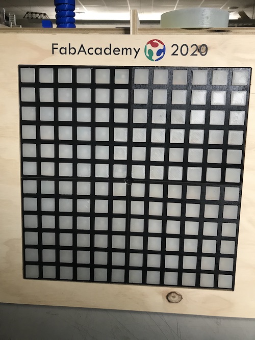
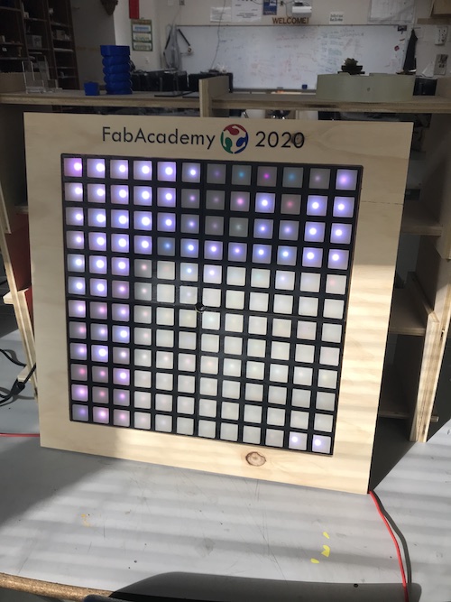
Feedback from Neil
After my oral presentation, Neil requested that a put a better video on my site of my mirror working. Here is a waterbottle being held in front of the camera and the neopixels updating. Though the quality is subpar because of the limited number of pixels, you can see the color of the waterbottle and what is in the background.