3: computer controlled cutting
Vinyl Cutting
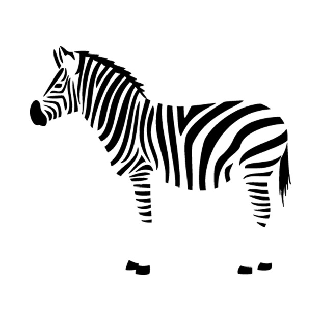
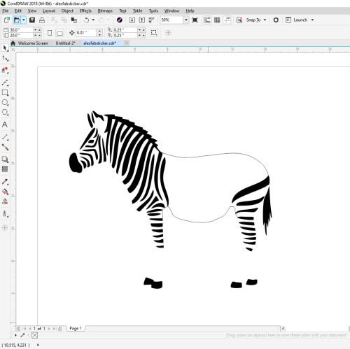
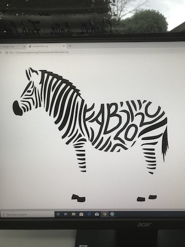
To begin the week, one of the individual assignments was to create a vinyl cut sticker. I had the idea that I wanted to cut out the silhouette of a zebra and edit the stripes to say some sort of FabAcademy related phrase. I found a simple zebra silhouette on Google that I liked.
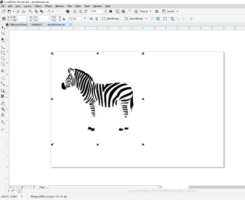
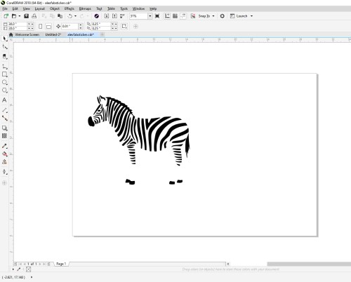
I imported the file into CorelDRAW to begin editing it. I needed to make the image a bitmap so I could edit the lines and nodes. On the top menu, I selected Trace Bitmap -> Outline Trace -> Detailed Logo and then clicked okay. This traced the image to be a bitmap, deleted the original image, and removed the background.
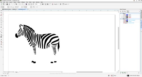
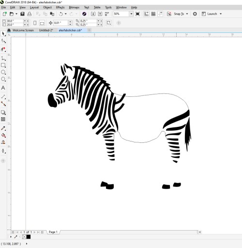
Next, I made a separate layer under the Object Manager toolbar on the right side of the page. I wanted to use the layers to separate the editing of the stripes and other lines I would use as guides. I renamed the layers “stripes” and “outline.” On the outline layer, I outline the top and bottom of the zebra so that I would know where to delete my new stripes once I created the letters.
Using the Virtual Segment Delete tool on the right toolbar, I deleted the stripes that were in the middle of the zebra. This was where I would add my letters and additional filler stripes.
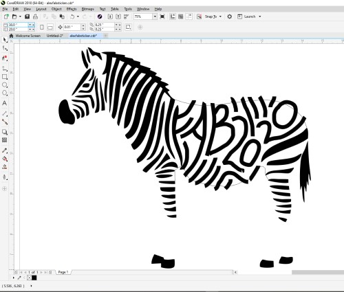
I then selected the Freehand tool to start writing my letters. I chose the concise phrase “FAB2020” to signify the year I am taking this course–FabAcademy2020. To match the thickness of the default stripes, I made my Freehand tool size 14pt.
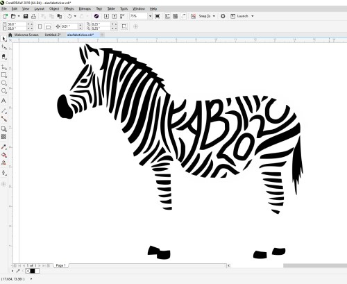
Once I had written my phrase and added some more stripes to take up space and fill the body of the zebra, I had to clean up the edges of the zebra and make the edges of the new letters and stripes more smooth and similar to the existing ones. I used the erase tool to erase the edges that went over the outline and the Freehand tool in white to smooth the new stripe edges.
I saved my Corel file as an SVG and saved the file so that I could open it in Silhouette Studio to cut it out on the vinyl cutter.
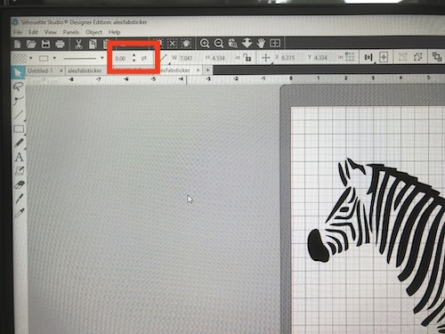
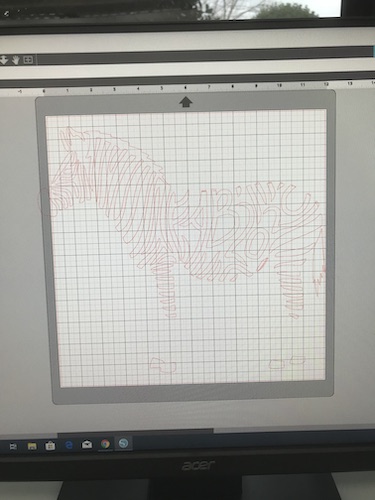
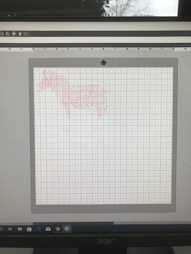
When I first opened my design in Silhouette, the text portion was very thin and did not match the other stripes. I fixed this by selecting the area and using Silhouette’s line thickness tool and increasing the size of the lines to 11.75 pt.
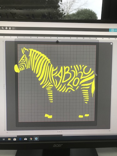
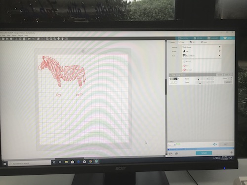
Next, I clicked on the butterfly-looking icon on the right toolbar and then selected Select Trace Area.
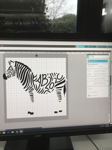
This selected everything that would be cut, which is seen in yellow. I then clicked Trace under Trace Style, deleted the original image, and scaled it down.
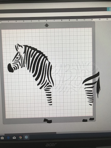
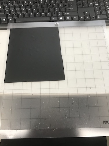
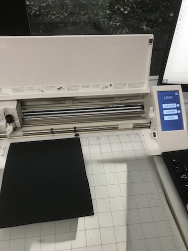
I selected matte black vinyl to make the zebra and cut a rectangle of it a little bit bigger than what the dimensions displayed in Silhouette. I stuck the vinyl on the top right corner of the cut mat, matching what was shown in the software. Once it was securely stuck on the mat, I loaded the mat into the vinyl cutter using the Load Cut Mat command.
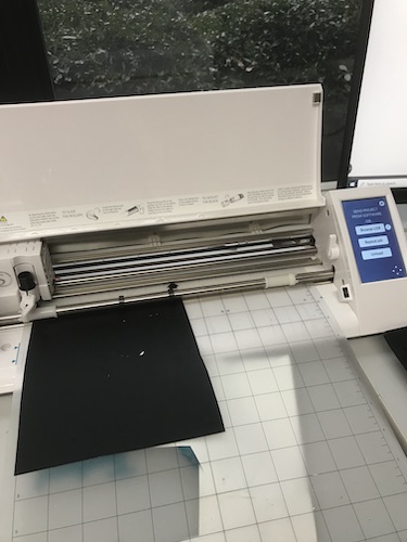
Now that the design was ready to be cut, I selected Send in the top right, changed the material to “Vinyl, Glossy,” and pressed send.
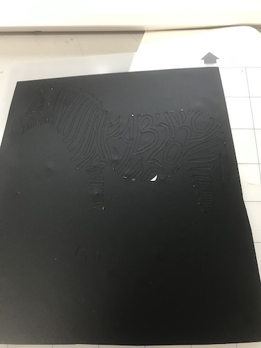
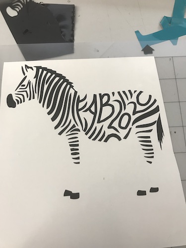
Once the cut was finished, I pressed Unload on the machine and peeled off the excess vinyl.
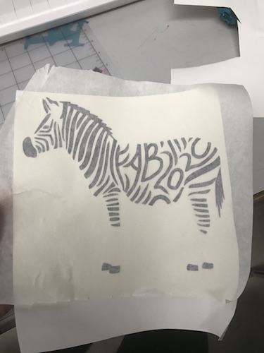
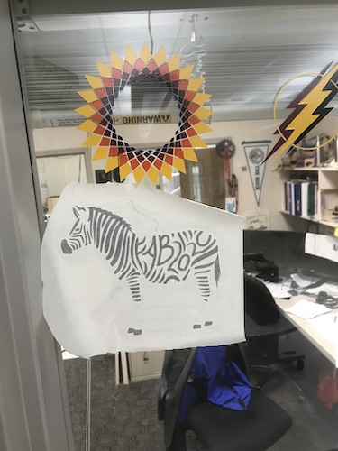
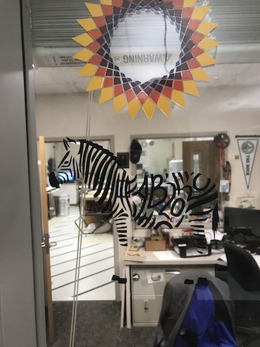
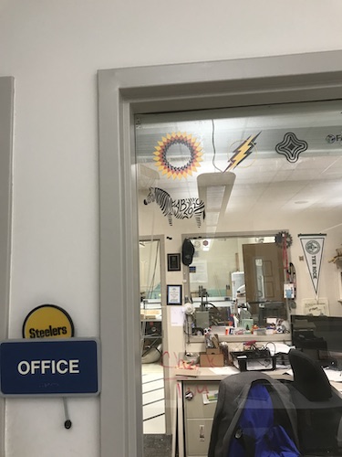
Next, I used transfer paper to stick to my sticker so I would be able to place it somewhere. My engineering teacher is beginning the tradition of all the FabAcademy student stickers going on his office window, so that is where I placed mine. I pressed down on the transfer paper, ensured everything was smoothed out and there were not air bubbles, and feeled off the transfer paper. Voila!
Parametric Design
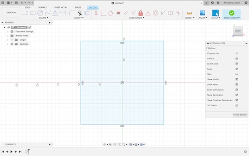
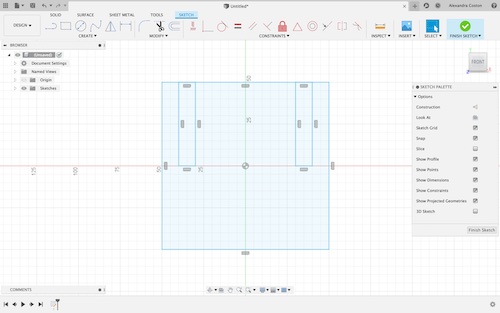
The next individual assignment was to create a parametric construction kit. I decided to use Fusion to design my pieces, then transfer the files onto Corel to laser cut them. I watched two videos to learn the basics of using parameters, one by Maker’s Muse and one by Fusion360. My first design used only one piece as I was learning how to use parameters to change dimensions. I wanted to make a simple honeycomb shape. I started with a two-point rectangle and then made two small rectangles for tabs.
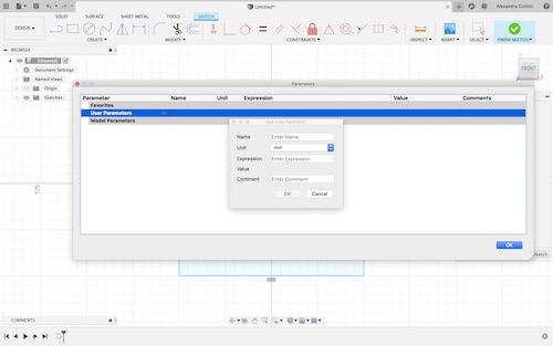
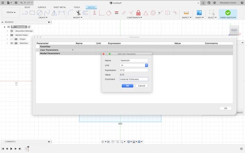
I then went under Modify -> Change Parameters to start playing around with the parameters. You can create parameters for your design by clicking the ‘+’ next to ‘User Parameters’. It prompts you to enter a name for the parameter, unit of measurement, expression (the value), and any comments you might have to describe the parameter.

The first parameter I made was for the width of the tabs. I named it TabWidth and used the value 0.13in which is the thickness of the cardboard I would use. I commented “material thickness” so I would know to change this parameter if I used other material to cut this design.
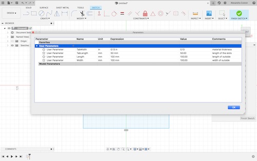
I ended up making 4 parameters total: TabWidth, TabLength, Width, and Length. I kept the TabWidth in inches but I put everything else in mm.
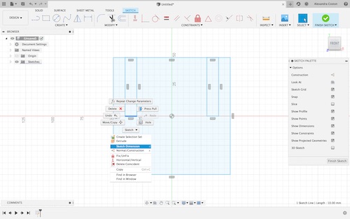
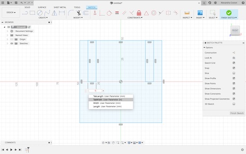
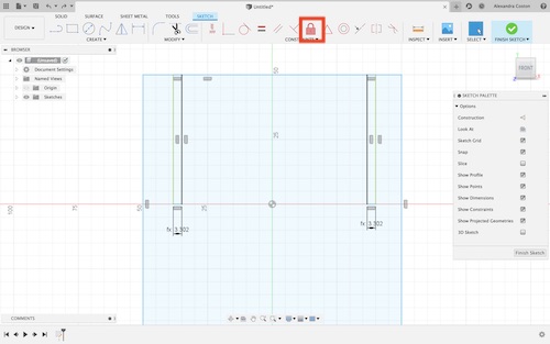
In order to change the dimensions of my design in accordance to my created user parameters, I had to click on the lines I wanted to change and select ‘Sketch Dimension’. I was then able to type in the name of my parameter and the values would automatically adjust.
In order to change the size of the tabs without their positions changing, I used the ‘Fix/Unfix’ constraint to fix one of the lines on each of the tabs. This way, no matter how their dimensions changed, they would stay in the same spot.
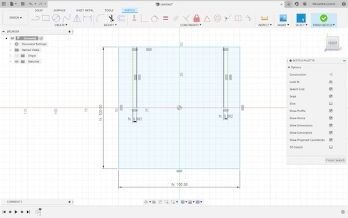
I used Sketch Dimension to enter each parameter. You can tell that the dimension is a parameter because of the “fx: __”. Now that my sketch was finished, I was ready to extrude it.
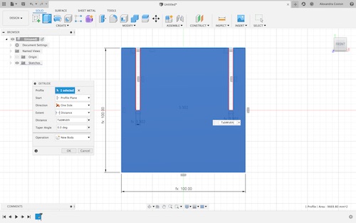
Because the width of the tab was the material thickness, I used the ‘Pull’ command to extrude the sketch ‘TabWidth’. This would make it 0.13in thick–the size of the cardboard.
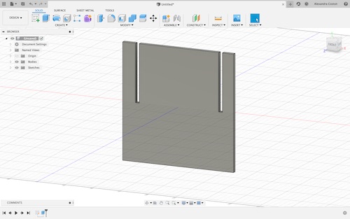
Here is the final extruded body.
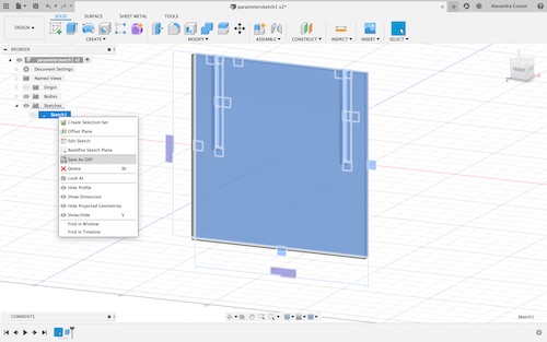
I clicked the sketch and selected “Send as DXF” to export my file.
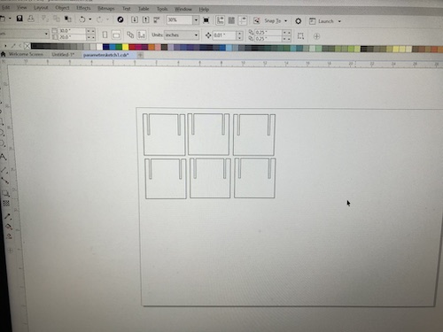
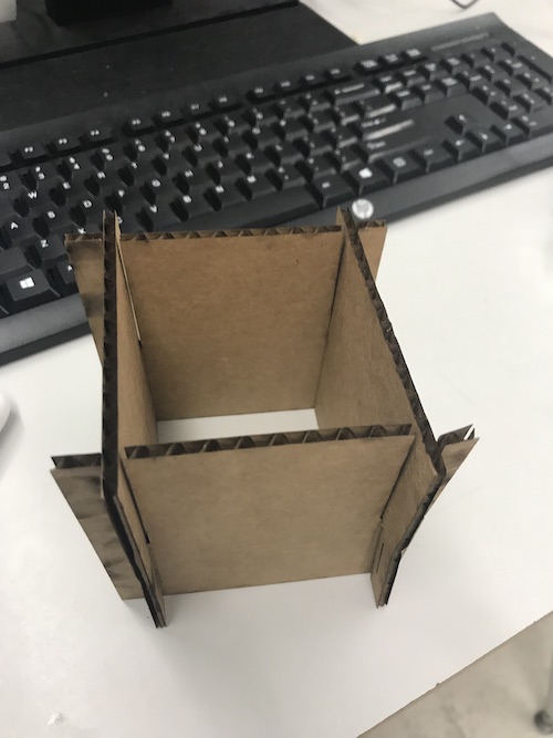
Once I opened it into Corel, I made 6 of the design to cut and arrange in a hexagonal shape.
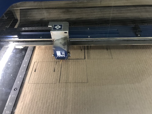
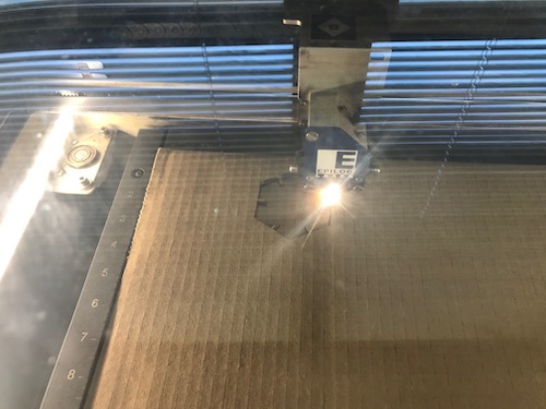
I cut the pieces on the laser cutter using 0.13in cardboard and the settings 15% speed, 100% power, 10 frequency. I then put the pieces together.
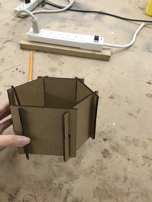
I could also arrange the pieces into a square rather than a hexagon if I so desired.
You can download the file for this design here.
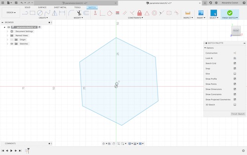
Now that I knew the basics of using parameters, I made another small, simple design using two bodies–a hexagon and a rectangle. I started off with a sketch of a hexagon that I made using the Polygon tool.
I then made a construction line to locate the midpoint of the side I would draw a tab on so it would be centered.
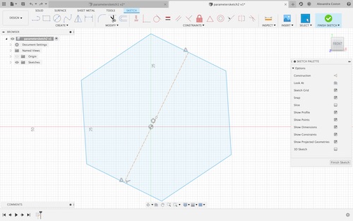
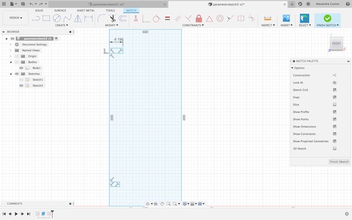
I made a tab using the line tools with random dimensions that I would change once I added my user parameters.

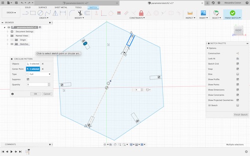
Next, to repeat the tab on all six sides of the hexagon, I used the Circular Pattern tool under Create. I selected the three lines that made up my tab for the Objects component, then clicked the center of the hexagon for the Center Point, and finally typed in 6 for the number I needed.
The first parameter I made was once again TabWidth to specify the material thickness and allow me to change it if necessary.
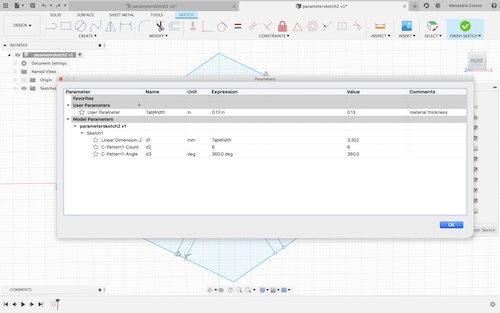
I made another parameter for the amount I would need to ‘pull’ the bodies: Extrude. I should have used TabWidth like I did for the last design, but I forgot.
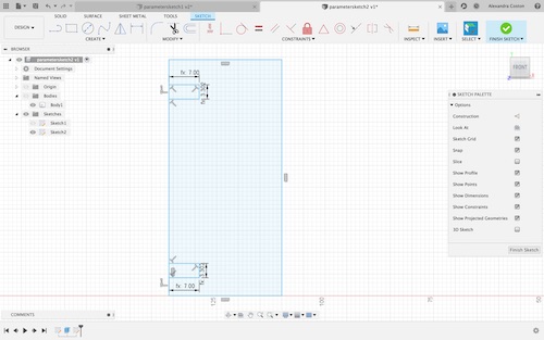
I went back to my sketch and created the parameter TabLength. What is cool about parameters is the body automatically updates after the sketch is changed. As you can see, the tab that I changed has length fx: 7.00 because that is the expression in the user parameter. Additionally, because I used the Circular Pattern tool to create all my tabs, editing the original tab automatically changed the other five.
Next, I started making the rectangle portion of my design. I planned to cut two hexagons and six rectangles to put the design together. I started off by making a rectangle and two tabs of different dimensions.
In order to make the tabs the correct dimensions to fit with those made on the hexagon, I used the parameters I made–TabWidth and TabLength–to make the tabs the right sizes. The placement of these tabs did not really matter.
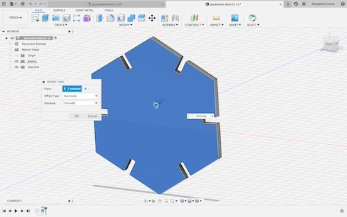
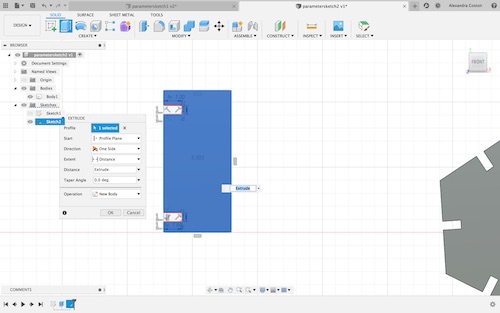
Finally, I extruded the rectangle using the parameter Extrude.
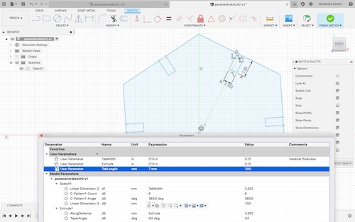
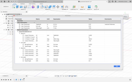
You can see all the parameters I ultimately used. I only made three, but this allowed me to create two bodies that would fit together and change their dimensions at once if I needed to in the future.
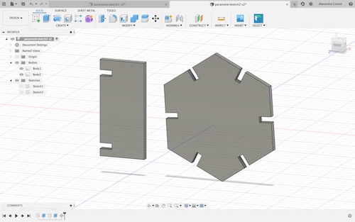
Here are my two final bodies.
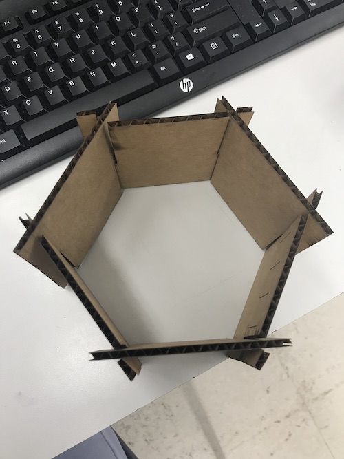
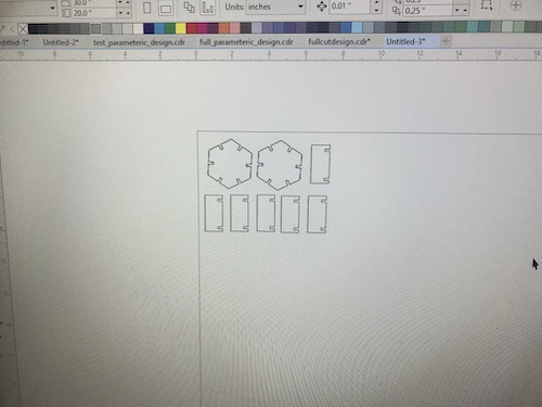
I once again saved the sketches as DXF’s and imported them to Corel. I cut two hexagons and six rectangles.
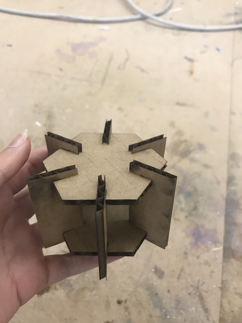
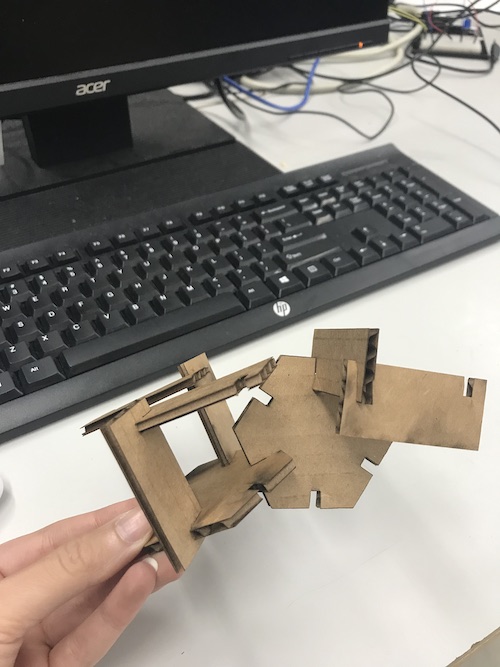
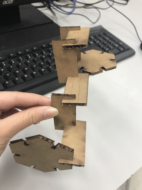
I put together my design the way it was intended to fit together. Though, as you can see, it can go together many different ways because of the same-size tabs. The pieces fit pretty snugly because of how small the kerf value of our laser cutter is.
You can download the file for this design here.
To download my files for this week, click here.
Group Assignment
Our group assignment for this week was to characterize our lasercutter’s focus, power, speed, rate, kerf, and joint clearance. You can read about the whole process here and visit my peers’ pages for their individual contributions. All members of the group contributed in different areas. I personally helped in defining the terms to characterize our laser cutter (e.g. kerf), creating and engraving the files to display focus levels, cutting and measuring the kerf of our laser cutter, and working on documentation for our group website.
This assignment taught me how differences in focus, power, speed, and rate values change cutting and engraving on the laser cutter. In addition, I learned how to account for kerf on the laser cutter and the nuances of joint clearance, specifically making pieces fit together in specific ways.
To download my files, click here.