4: electronics production
Programmer
The individual assignment for this week is to make an in-circuit programmer by milling and stuffing the PCB and testing it.
My peers and I used this tutorial for the entire process of creating our programmers.
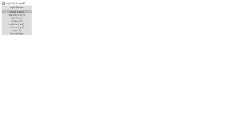
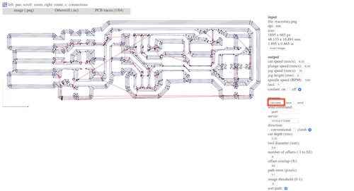
The given tutorial provided the traces and ]outline of the programmer as PNG’s. Thus, the first step was to take these images and create a Gcode file in order to generate the toolpaths that the milling machine could read and use. For this process, I used Fab Modules. I was prompted with the opening page:

I selected ‘input format’ and clicked ‘image (.png)’, then chose the image I downloaded of the programmer traces.
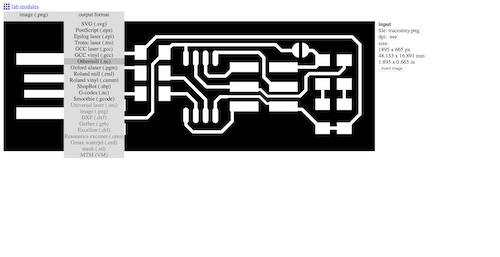
I then clicked ‘output format’ and selected the file type I needed: ‘Othermill (.nc)’.
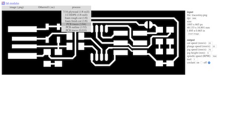
Next I selected ‘process’ and chose the bit I would be using to mill the traces, ‘PCB traces (1/64)’.
I changed two settings, the spindle speed to 12,000 RPM and the cut depth to 0.25 mm, based on Bantam’s Speeds and Feeds chart. These settings are discussed on our group assignment site.
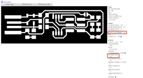
Finally, I clicked ‘calculate’ to generate the toolpaths, and saved the file. This file could be exported to the Othermill to be milled.
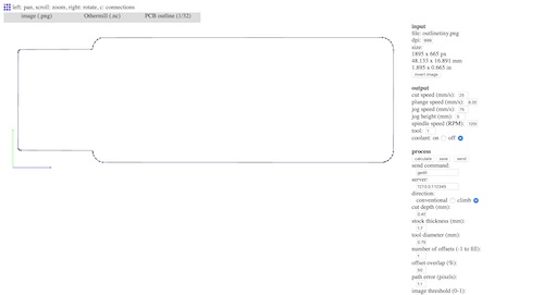
I repeated this process for the outline of the programmer, though I used the 1/32” bit, changed the spindle speed to 12,000 RPM again, and changed the cut depth to 0.45 mm.
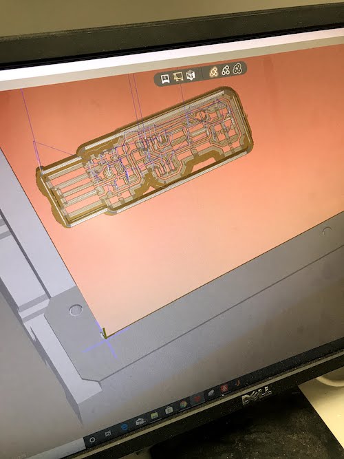
The next step was to mill my programmer. To start the process, I first downloaded the correct files and opened them in the program Bantam Tools. I moved the design in 4mm x 4mm so it would not be directly on the edge of the PCB.
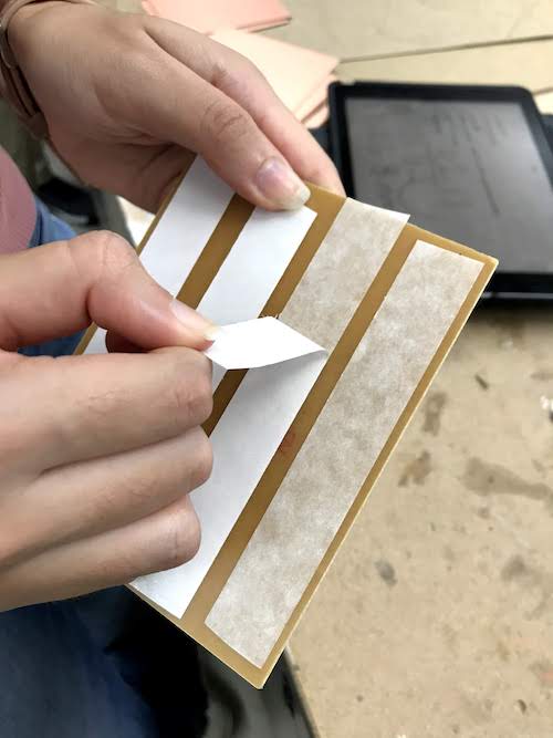
Next, I took a piece of PCB and attached several strips of NETO tape to the back of it. NETO tape is double sided, so it securely attaches the PCB to the plate of the milling machine.
I measured the length and width of the PCB and set these dimensions in the side bar with all the settings. In the milling machines, the origin is in the bottom left corner. I used this point to line up the PCB and stick it on the bed.
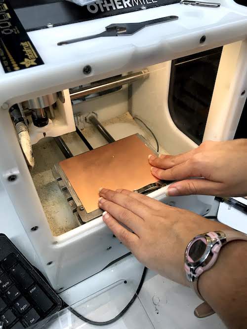
I then needed to locate the bed and the material to set the z-axis accordingly. I used a PCB Engraving Bit 0.003”, which I learned how to carefully insert into the machine. Once the bit in the machine is changed, the plate is located by having the bit slowly drop and touch the bed. Then, the machine finds the material thickness by slowly dropping the bit, touching the material while the clip is on it, and sensing the electricity conducted. I did this by selecting BitBreaker -> Probe Material Thickness. Once the origin was reset and the dimensions were confirmed, I began milling the traces of the programmer. I had to repeat this process–changing the bit, re-homing the axes–so I could cut the outside of the programmer. Once it was finished, I was able to use a scraper to pry the PCB off the plate.
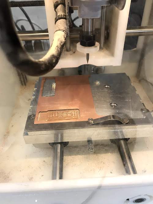
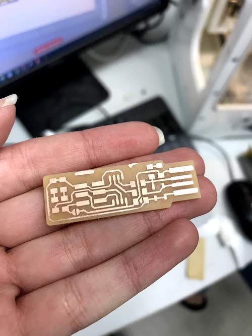
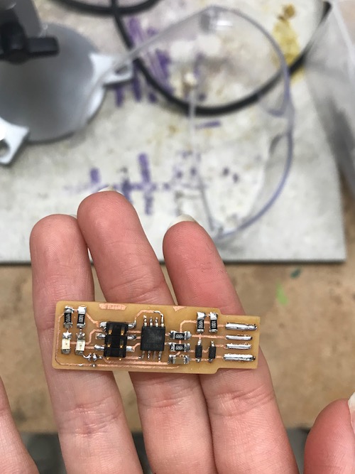
My programmer was milled!
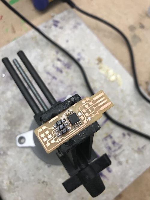
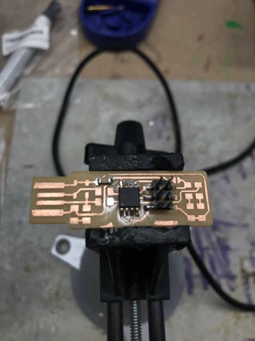
Following this was surface-mount soldering. I soldered the components starting from the inside and working outwards. I placed solder down, put down the piece, then reheated the solder to keep it in place. I then soldered the other pins or sides. Using this technique, I first soldered the ATtiny45 chip.
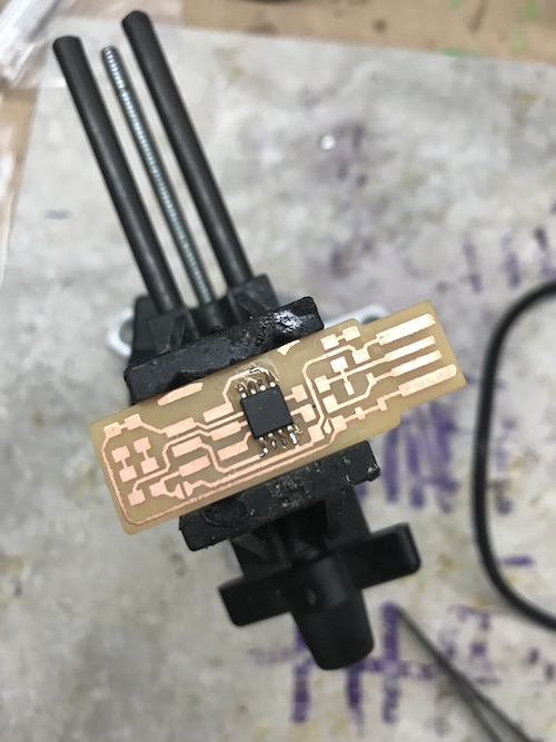
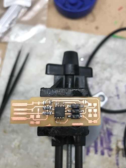
I then worked my way out, soldering the pin headers, capacitor, resistors, diodes, and LED’s.
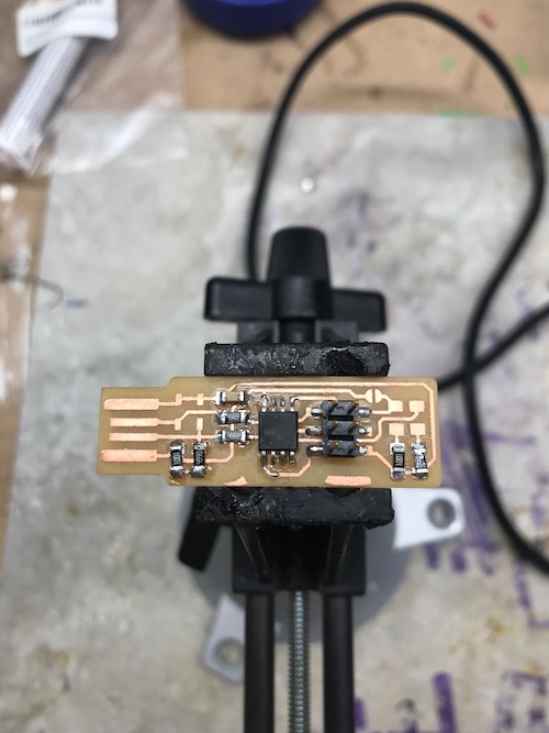
Finally, I added solder to the USB contacts on the board and the bridge.
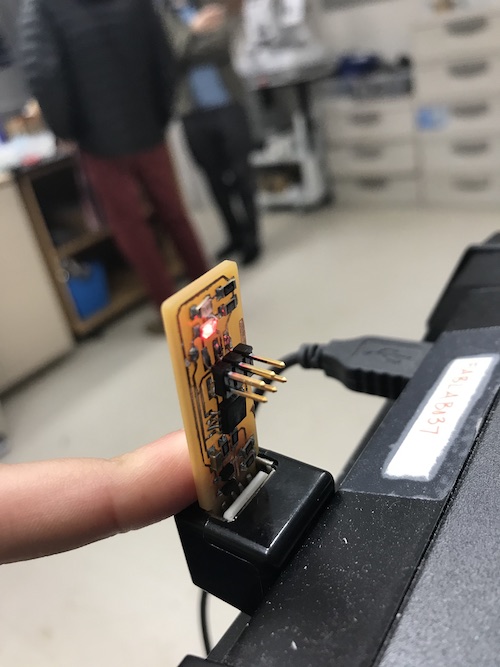
I plugged in my programmer into a USB port to see if it worked. The red LED lit up, indicating that my soldering was sufficient and my programmer was ready to be programmed.
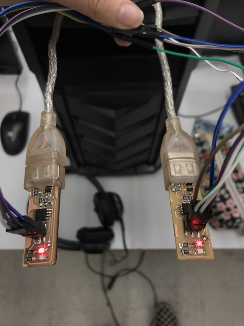
Once the hardware portion was complete, it was time to focus on the software. Because of some issues with my Mac laptop, I opted to use the Windows PC’s at my school’s lab. I connected my programmer to one USB port and my peer’s programmer that had already been programmed to the other port.
Though there is a tutorial provided for what software to download here, I will detail the steps I took:
-
install AVR8 GNU Toolchain from Microchip, extract the files and extract them to
C:\Program Filesso that all the software will be in the same folder that the computer knows -
install GNU Make, extract the files and put them into Program Files
-
install AVRDude, unzip the files and put them into Program Files
-
go into File Explorer (where are the documents and downloads are) and go to the “bin” folder inside the AVR8 GNU Toolchain folder installed, and copy the directory path
C:\Program Files\avr8-gnu-toolchain-win32_x86\bin. -
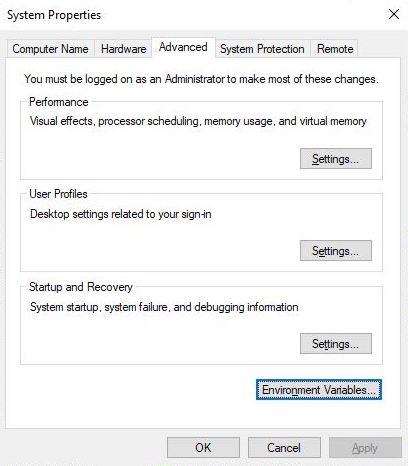
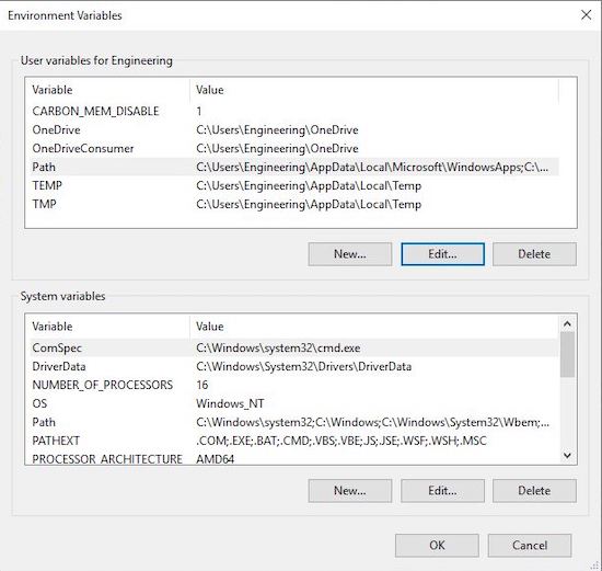
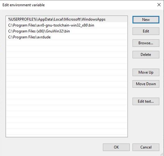
open Path on the PC, select Environment Variables -> Path -> New, and paste the directory path that was just copied
-
paste two other values:
C:\Program Files (x86)\GnuWin32\binandC:\Program Files\avrdudethen click OK
-
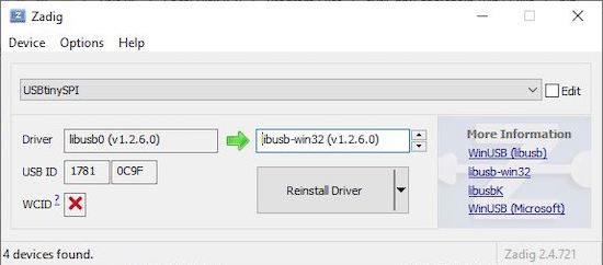
install Zadig, the drivers for the programmer, and plug in the blank programmer into the PC’s USB port
-
select Options -> List All Devices, then find USBtinySPI in the drop down and select it to the right of the green arrow, click the down arrow once so it reads
libusb-win32 (v1.2.6.0), then click “Install Driver”
-
open Windows PowerShell on the PC and change the directory by entering
cd C:\Program Files -
next, use the commands
make allto compile everything,make flash,make fuses, and lastlymake rstdisblif all the commands went through successfully, the solder bridge can be removed and the programmer is programmed!
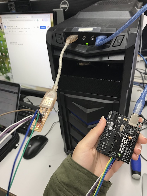
Once my programmer was programmed, I was ready to try programming something else. I acquired an Arduino Uno that I attached to my programmer using female-to-female and male-to-female wires. I had to be careful and line up the Arduino correctly when attaching it to the programmer. I inserted my programmer into a USB extension before plugging it in to the PC so that I would not mess up the PC. Here are the steps to program the Arduino once the hardware was set up correctly:
- download Arduino and open a new sketch
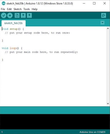
- click File -> Examples -> 01.Basics -> Blink to open to simple Blink code
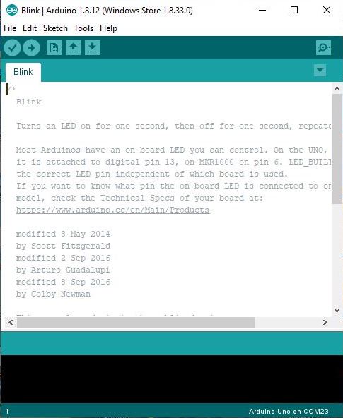
-
click Tools:
- under Board select Arduino Uno
- under Port select the serial port COM__ (just not COM1)
- under Programmer select USBtinyISP
-
click File -> Preferences -> Show Verbose Output and select Check Compilation, then click OK
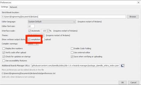
-
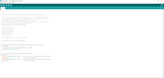
use the normal Blink code, you can edit the
delay(1000), to change the amount of time the LED blinks for, but I left it the default time. -
click Sketch -> Upload Using Programmer to upload the code through the programmer instead of directly to the Arduino
To download my files for this week, click here.
Group Assignment
The group assignment for this week was to characterize the design rules for the PCB production process: document feeds, speeds, plunge rate, depth of cut (traces and outline) and tooling. All of my peers played different roles in completing this assignment, though we did work collaboratively. To read about our process, you can visit my team’s group page here. My individual contributions included defining the terms to describe PCB production (e.g. plunge rate), exploring Fab Mods and Modules in order to generate a Gcode file to send to the milling machine, and milling the traces and outline of the ruler itself. Because our initial trace depth was not deep enough to penetrate the copper on the PCB, we had to do a bit of trial and error editing the Z axis value before the traces were milled out properly. I helped with this process of confirming the position of the bed and thickness of the material in order to correctly mill the traces.
Throughout this group assignment, I learned what the design rules for the PCB production process were and how to alter them. Additionally, I learned how to use Fab Modules, specifically importing a PNG image, generating the toolpaths, and producing a .nc file to export to the Othermill. Lastly, I became comfortable with milling boards on the machine and navigating Bantam Tools in order to establish the correct settings.