2: computer aided design
The assignment for this week is to model our potential final projects on as many different platforms as possible.
2D modeling
Inkscape
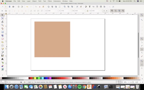
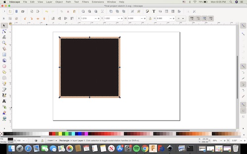
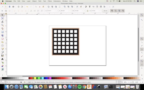
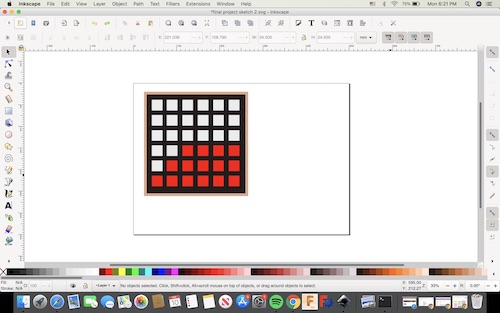
I downloaded Inkscape on my laptop to start modeling my project in 2D. It was pretty simple to navigate and use. I drew a square and used the color spectrum at the bottom to make it’s fill brown. I changed its dimensions to be 9.5in by 9.5in. This would be the plywood backboard. I then drew a 9in by 9in black square to be the Neopixel strip frame. Next I copied and pasted small squares with white fill to show the holes in the frame. Finally, I changed the fill of the squares to be 7.5% gray (for the unlit Neopixels) and red for the Neopixels that were outputting whatever image or shape was seen in the input.
CorelDRAW
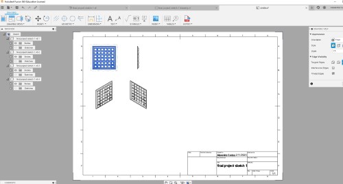
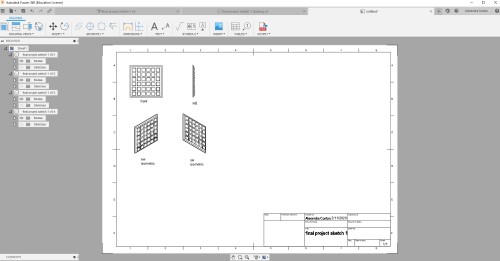
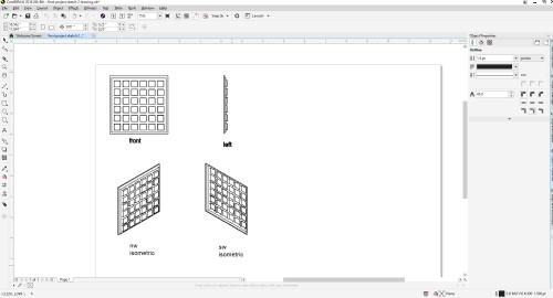
Because I designed my 3D model in Fusion 360 first, I decided I wanted to try and export it as a sketch to Corel so I could edit it. In Fusion, I clicked on “DESIGN” in the top left corner, then hit “DRAWING”, then “From Design.” This generated a drawing of my 3D design that I could view in different views. The default view was the front-facing view. I inserted several others by clicking on the original view and selecting “edit base view,” which produced a menu on the right side that allowed me to change the view. The different views include top, front, home, bottom, left, right, back, SW isometric, SE isometric, NE isometric, and NW isometric. I chose to do four views: front, left, SE isomentric, and NW isometric. I used the text box tool to label each view.
You can download this version of the file here.
Next, I was ready to export it to Corel. I clicked on “PDF Output” on the top toolbar and saved my sketch. I then opened Corel and imported the pdf file.
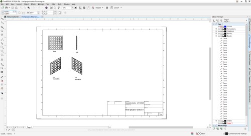
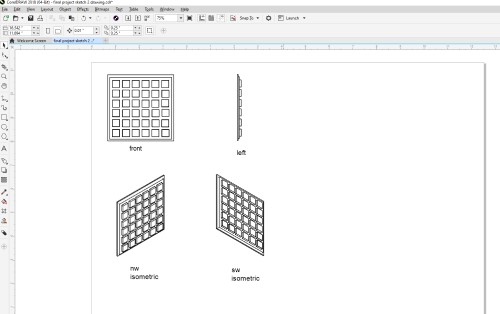
The pdf file made everything into simple lines, so I was able to easily edit and delete things from the sketch. I deleted everything else but the four views of my design.
To make the sketch more detailed, I used the Object Properties toolbar to change all of the lines to 1.5pt. This also allowed for more specificity when I was editing the lines.
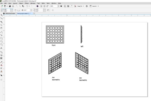
Because parts of my sketch were inconsisent, I decided to add lines to make everything more uniform and cohesive. I used the Freehand line tool to fill in the gaps on my design. All the lines snapped to the nodes easily.
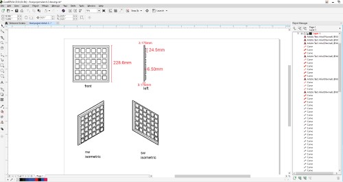
Lastly, I added the dimensions of each component of my design in red by simply making brackets in red and text boxes.
3D modeling
Fusion 360
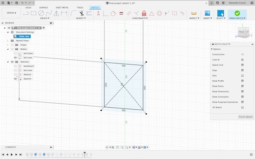
I have used Fusion 360 a bit in the past, so that is where I chose to design my project. I started out watching some videos about sketching. I watched the sketch concepts videos to refresh my knowledge of some basic sketching tools. I opted to complete some sketch tutorials for more hands-on learning. The first tutorial was learning how to create a sketch and then make it 3D. The next tutorial I completed was learning how to use constraints on Fusions. Constraints allow you to relate different components together. They stay fixed even when you change the shape or dimensions. They are extremely helpful for when you need to rescale a design or change parts of it.
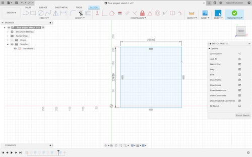
After I felt comfortable sketching on Fusion and making objects 3D, I went ahead and started modeling my final project. The three parts I needed to make were the backboard where the Neopixels would be attached, the frame for the Neopixel strips, and the individual LED covers so the mirror would have a pixelated image effect. I created separate sketches for each piece, which is basically making different layers for each part. This allowed me to separate the bodies.
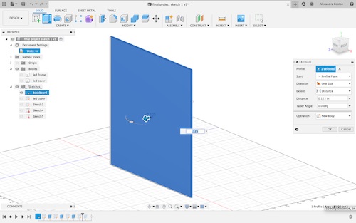
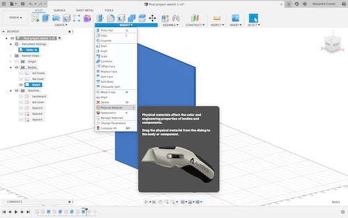
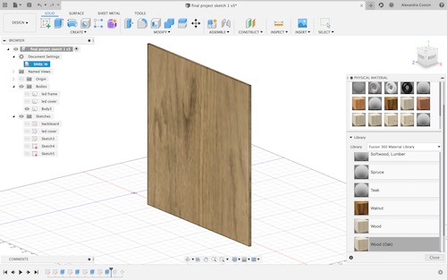
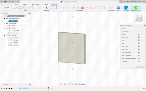
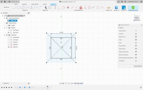
First, I made a square and used the key ‘q’ or “pull” to extrude the square 0.125 in (the size of 1/8in plywood). I then used the “physical appearance” tool to make it look like wood.
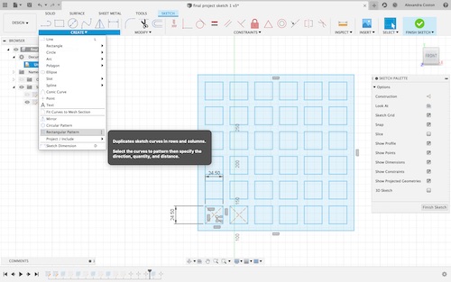
Next, I made a square and made numerous copies of it using the “rectangular pattern” tool so I would have a grid. I then traced a square around it and selected the inside portion to extrude using ‘q’.
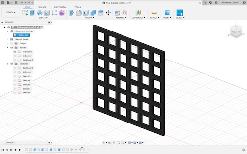
I made the piece black using the physcial appearance tool because I will spraypaint it. I then stacked the two bodies together.
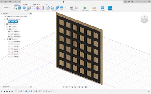
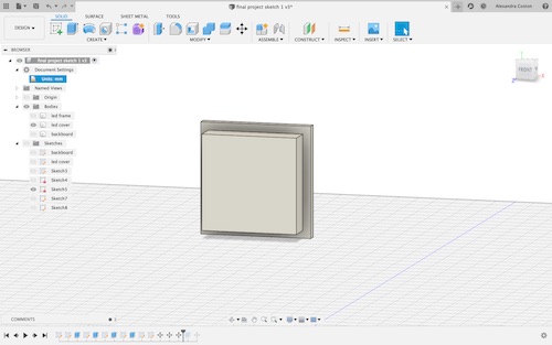
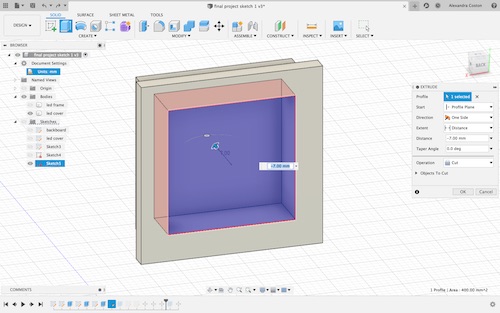
Finally, I sketched the individual LED covers. I made a square and extruded it. I then started a new sketch on the face of that square and made a smaller square and extruded it. I needed to clear out the inside of the shape so that the light from the Neopixels would shine through, so I sketched a square on the back of the body and extruded it in the negative direction.
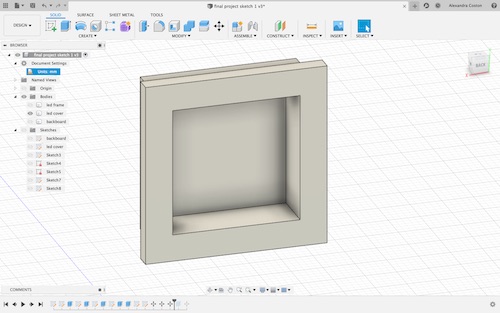
I then copied and pasted each of the invididual LED covers and placed them in the grid. Below is what my first final design looks like.
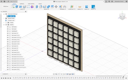
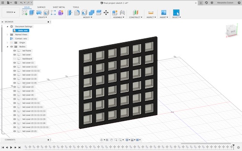
You can download the file for this design here.
FreeCad
I had never used FreeCad before, so I downloaded it and explored the program a bit. I started off by going into the “Part Design” workbench. I then created a new sketch.
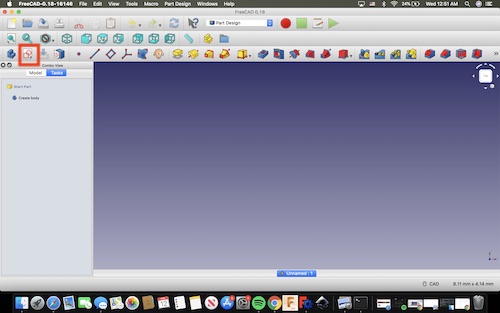
I selected the plane I wanted to work in, the XY plane, and then clicked okay to begin sketching.
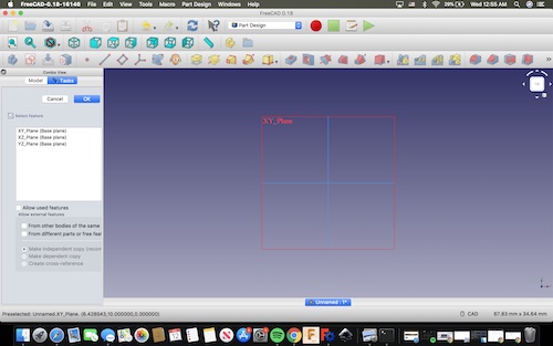
I wanted to try to make something very simple in FreeCad, so I selected the carrot next to the lines in the toolbar and selected the two-point rectangle.
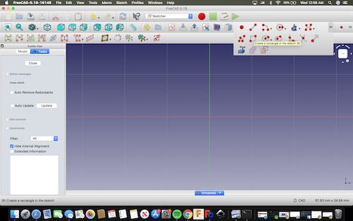
I drew a simple rectangle and clicked out of it.
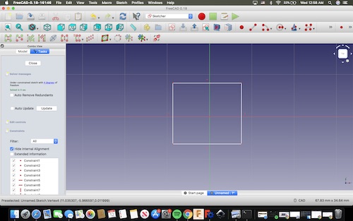
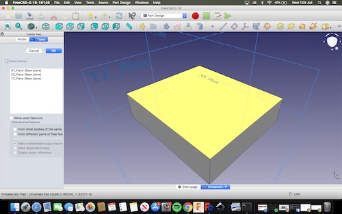
On the left side in “Tasks” is the option to create a body. I clicked this, clicked my rectangle, and pressed “Pad” on the top toolbar. This tool extrudes the sketch, and I was able to change how much it extruded on the left side. I extruded it 5mm.
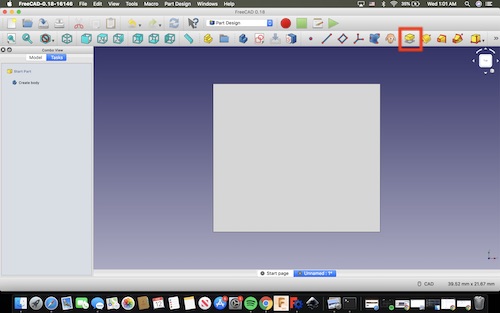
Though the rectangle is extruded, you cannot tell from the front view as it only looks like it has been filled in. I clicked on the small box by the view cube to change the view to isometric. This shows the new 3D figure.
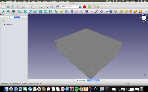
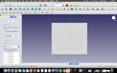
Next I selected the top face of the rectangle and selected “create sketch” again.
I drew a smaller rectangle on the face and then extruded it 1mm with the pad command.
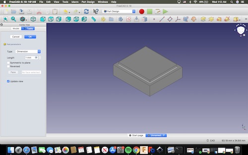
This was as far as I got with FreeCad, as navigating it was a bit confusing. It was interesting to learn but I prefer Fusion because it has a nicer interface and in my opinion is easier to use.
To download my files for this week, click here.