6: electronics design
Hello-World Board
The individual assignment for this week was to redraw an echo hello-world board, add (at least) a button and LED (with current-limiting resistor), check the design rules, make it, and test it.
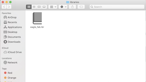
The first step was downloading Autodesk Eagle with my student license. I had never used Eagle before, so I started by watching their two part webinar here and here in order to learn the basics of how to use Eagle. While I probably should’ve made my circuit on another platform, Tinkercad for example, before beginning my actual design on Eagle, I jumped straight into creating my schematic. I downloaded the libraries I needed, a library for Eagle that Neil provided, fab.lbr, the Sparkfun libraries, and a library provided by my teachers that contained all the new components I would need, fab_new.lbr. Once the libraries were downloaded, I moved them into my libraries folder so that they would show up in Eagle.
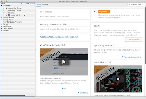
The library has a green dot next to it showing that it is active and able to be used.
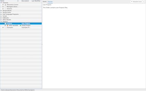
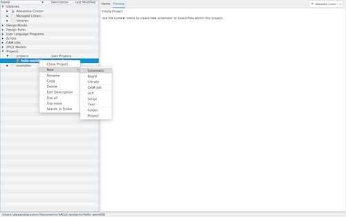
I went down to ‘projects’ and created a new one, which I titled ‘hello-world06’.
I then selected New -> Schematic.
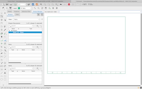
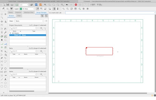
Once my schematic was created, I typed ‘frame’ into the commmand line to create a frame inside which I would draw my schematic. I dragged the rectangle and pressed ‘escape’.
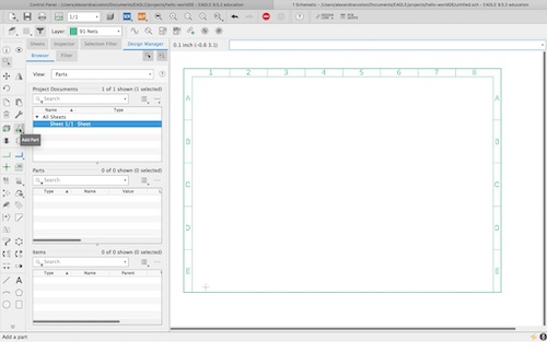
I decided to gather all my components first. I decided to create the ATtiny412 board, as my lab had just acquired the chips and they were supposed to be better than the ATtiny45 chips we used for our programmers. As such, I used Neil’s example board to create mine. I additionally needed to include a button and LED onto my board, so I added these components. The trickiest part of finding the components was not knowing what they were named, so I had to scroll through a bit to find what I needed. In order to insert a part, I selected ‘Add Part’ on the left toolbar.
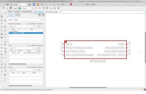
I found the ATtiny412 chip first.
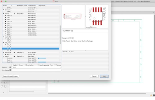
I clicked ‘OK’ and then moved the chip to the middle of my frame where I wanted it to be placed.
I clicked it and then the chip was placed, showing all the ports.
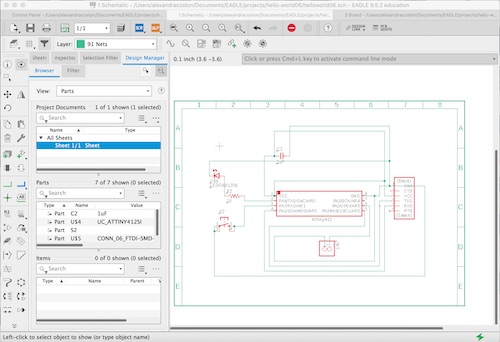
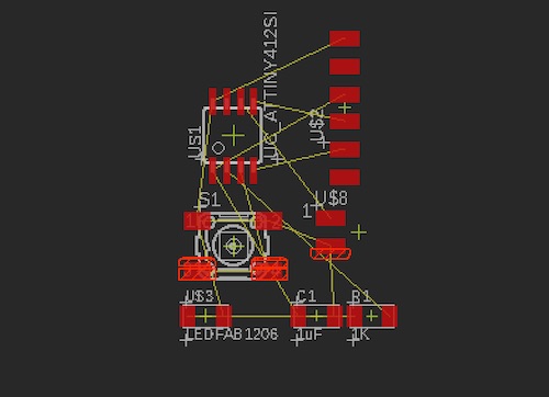
The remaining components I needed were: a capacitor, an LED, a resistor, a button, a 6x1 pin header, and a 2x1 pin header. I assigned the capacitor and resistor their respective values by clicking on the component and pressing ‘Value’. Once I had all the parts I needed, I moved them around and used the ‘Net’ command to connect them.
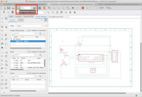
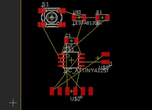
Once my schematic was finished, I clicked ‘Generate/switch to board’ to generate my board.
All my components were thrown into a corner, so I had to rearrange them and think about where each component should be placed in accordance with what it was supposed to be connected to. I also had to rotate some of the parts to make the routing easier.
I was ready to route the components once they were arranged in a suitable fashion. I did this by selecting ‘Route Airwire’ and connecting the components appropriately. I also changed my trace width to 12 mm. After routing everything, I selected the ‘20 Dimension’ layer and made the rectangle smaller so it would become the outline of my board.
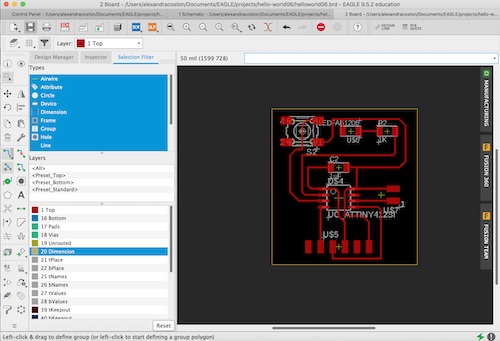
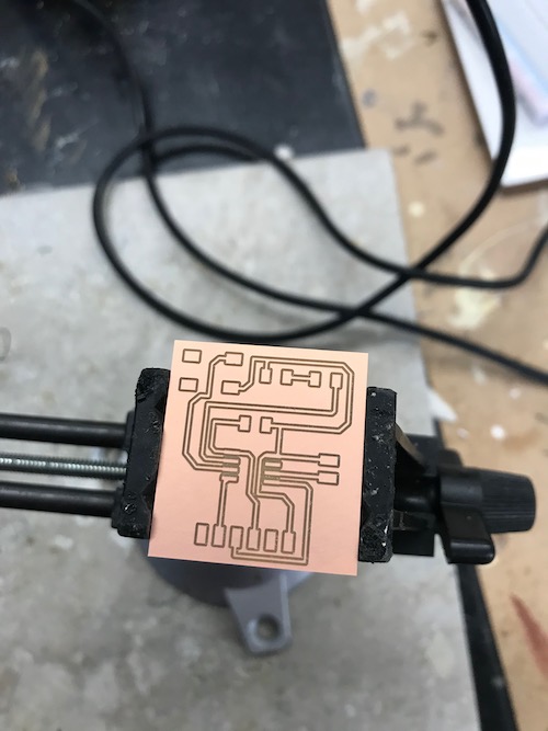
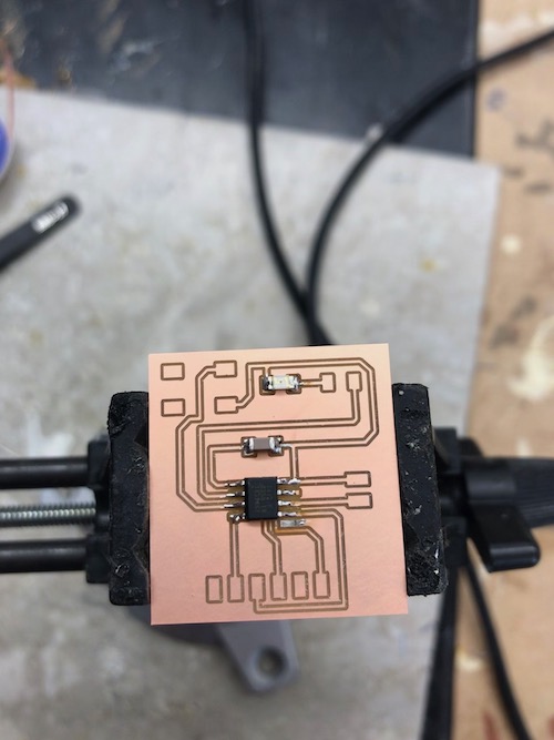
My board was ready to be milled! I saved the Eagle file, which automatically located itself into my project folder inside an Eagle folder. I imported the hello-world06.brd file into Bantam Tools. I used a 1/64” bit to engrave the traces and a 1/32” bit to cut the outline.
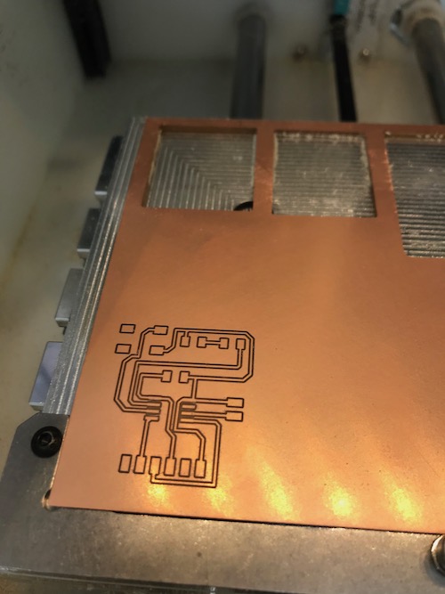
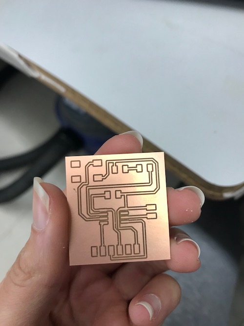
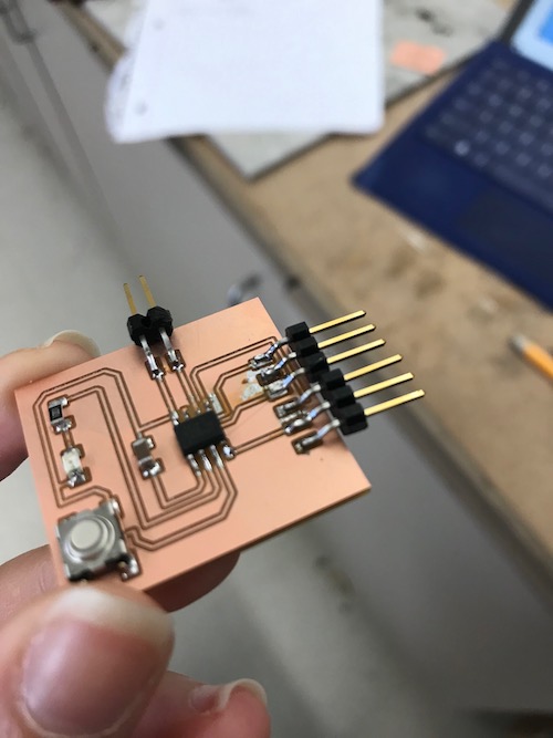
My board came out pretty nicely, so I began soldering immediately.
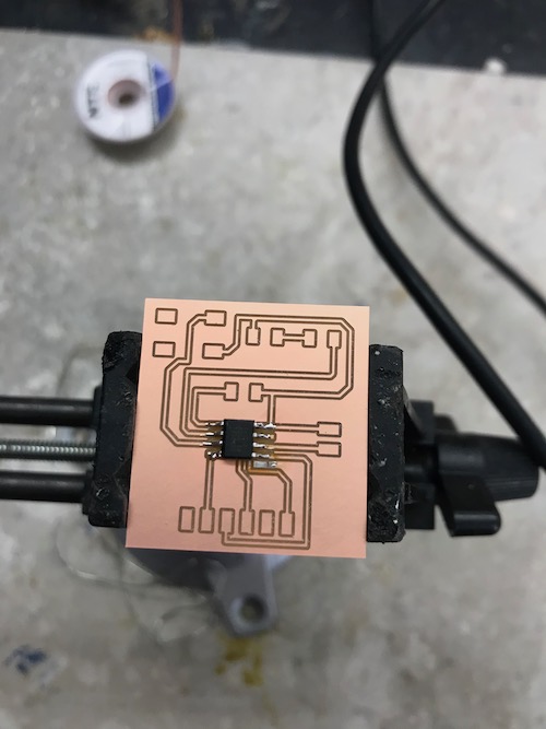
I soldered the ATtiny412 chip first, continuing the technique of starting in the middle and moving outwards.
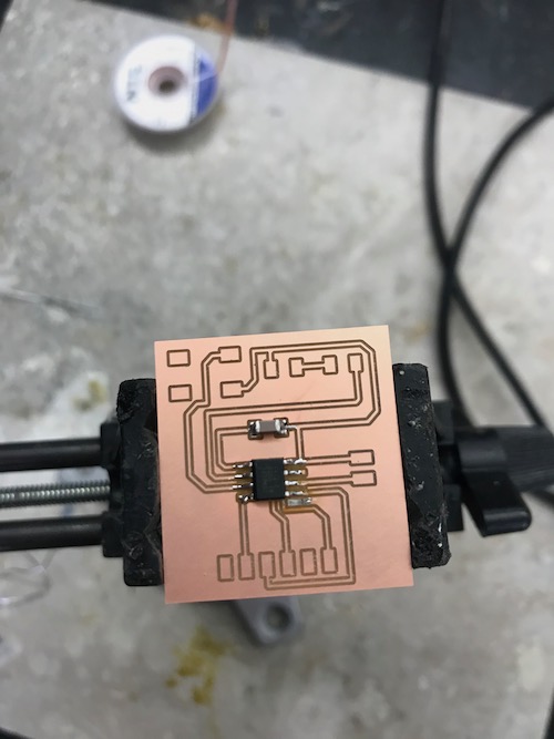
I then soldered the capacitor, LED, and resistor.
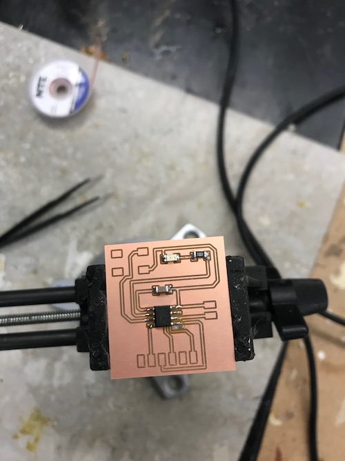
Lastly, I soldered the button and pin headers.
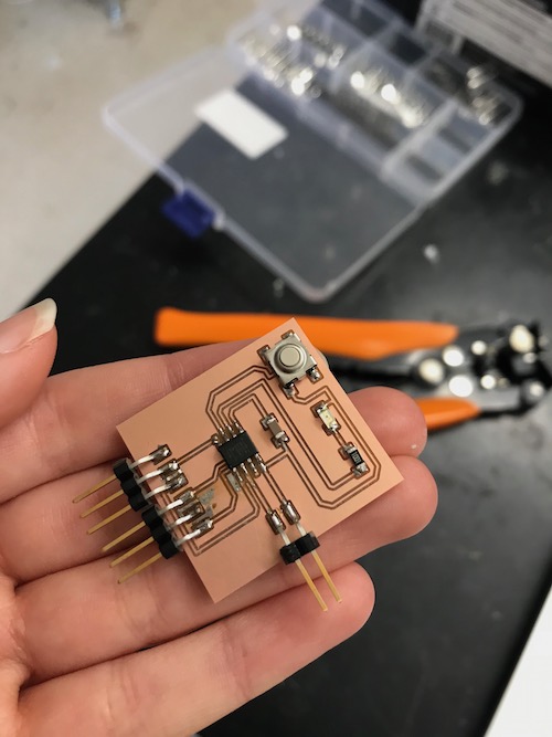
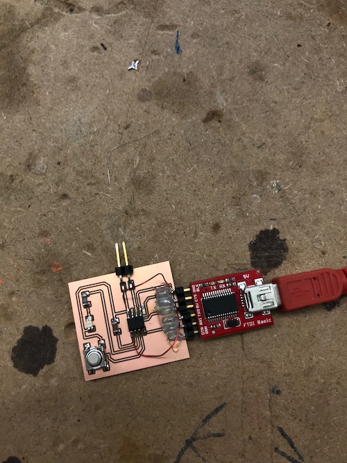
Instead of soldering a 6x1 pin header like I should have, I soldered 2 3x1 pin headers next to each other. This proved to be a mistake, because one of the sets pulled up the copper beds it was resting on after I finished soldering.
Luckily, the traces were still intact and I attempted to resolve the problem by securing all the pins with hot glue.
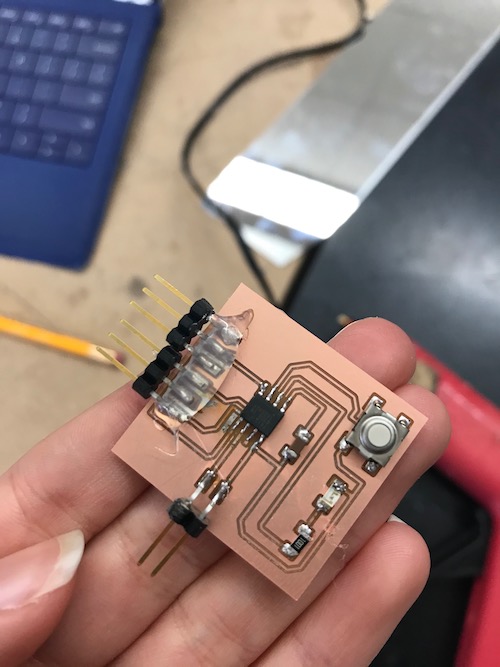
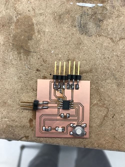
This solution worked when I uploaded some simple Blink code to my board. Unfortunately, when I went to upload Neil’s Hello-World code, my board did not work. I checked the connections with a multimeter, and found that my pins were not working anymore. Instead of scrapping the whole board and creating a new one because of two pins, one of my instructors, Mr. Rudolph, suggested using some wire to connect the pins that were not working, VCC and GND, to the corresponding spots on the ATtiny chip. I took two small pieces of wire and scraped off the coating on the edges using sandpaper to reveal the copper underneath.
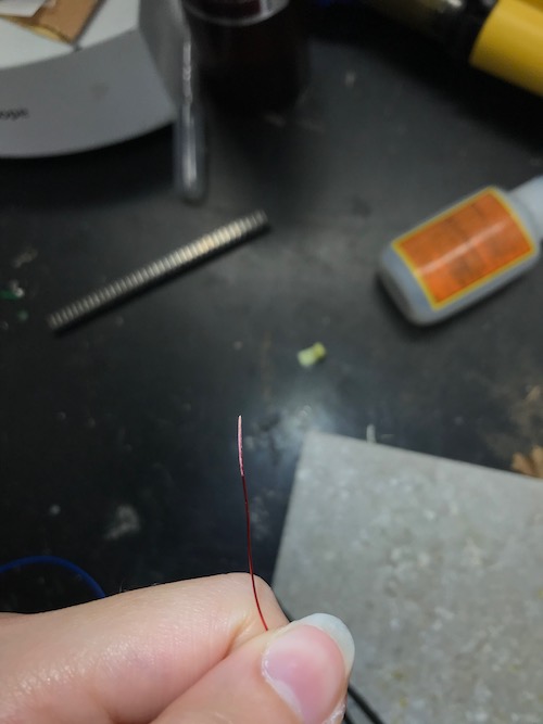
I then put some solder on each edge so it would make soldering to the board easier. Carefully, I solder one end of each wire to the pins and the other end to the chip.
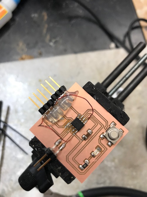
I reconnected my board to the programmer connecting 5V, GND, and UPDI. I uploaded the blink code once again and my board worked!
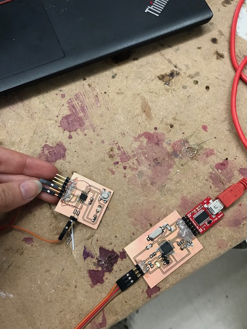
Finally, I was ready to upload Neil’s code once more. Once code uploaded successfully, I entered ‘hello world’ into the serial monitor. My board echoed it, as it was supposed to.
Once my board was finished and working, I went back and made the programmer that my instructor had let me borrow to program my board. The ATtiny45 programmers that we had previously made were not suitable to program these new boards. I used my instructor’s pre-made file and put it into Bantam to mill.
To download my files for this week, click here.
Group Assignment
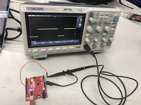
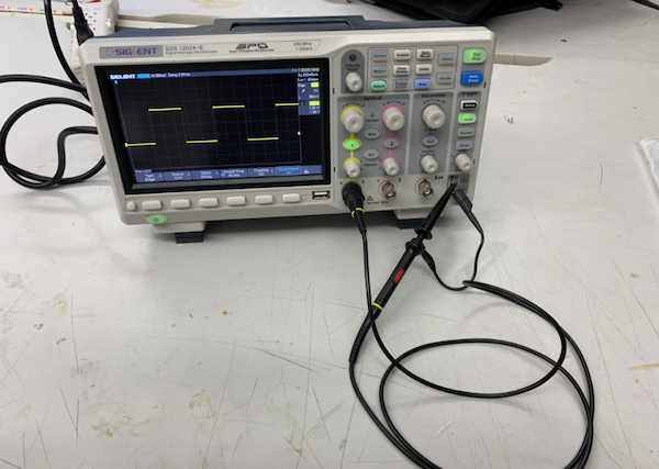
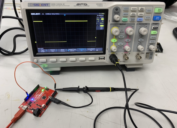
The group assignment for this week was to use the test equipment in our lab to observe the operation of a microcontroller circuit board. My peers and I split up into groups to learn how to use the oscilloscopes since our lab had several. We first watched a Sparkfun video to learn what an oscilloscope was and how to use it. The oscilloscope we used was the [SDS100X-E Series Super Phosphor Oscilloscope] (https://siglentna.com/digital-oscilloscopes/sds1000x-e-series-super-phosphor-oscilloscopes/). We followed the steps in the video to set it up. This included: - turning on channel 1 and turning off channel 2 - turning DC to Coupling - making sure the probe was on the 10x setting - under the trigger menu, setting Type -> Edge, Source -> Channel 1, and Slope -> Rising
Here is the correctly connected and calibrated oscilloscope.
We uploaded simple Blink code to an Arduino and then connected it to the oscilloscope. The probe tip went to pin 13 and the alligator clip went to GND. We then clicked ‘Roll’ and watched the oscilloscope’s display.
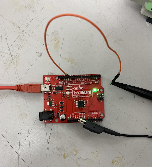
We also changed the blink code on the Arduino to be on HIGH for 3000 ms instead of 1000 ms. We then reconnected it to the oscilloscope to see this alteration.