5: 3D scanning & printing
3D Printing
The individual assignment for this week was to design and 3D print an object (small, few cm3, limited by printer time) that could not be made subtractively, 3D scan an object (and optionally print it).
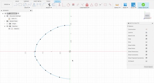
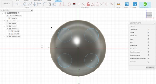
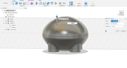
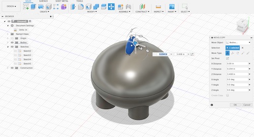
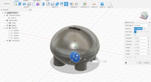
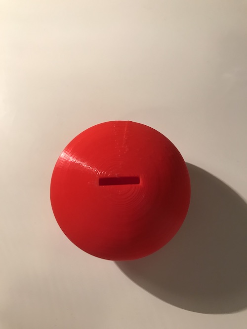
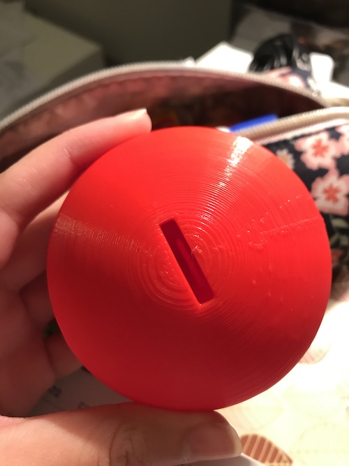
I decided to design something new to 3D print, and if I had time I would begin 3D printing the LED covers for my final project. I began designing a piggy bank of sorts–a hollow ellipsoid with a slot on the top to put in coins. In order to make this an object that could not be made subtractively, I decided to insert a coin inside the design of my piggy bank that I would dislodge after printing. I designed my piggy bank on Fusion 360.
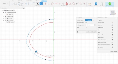
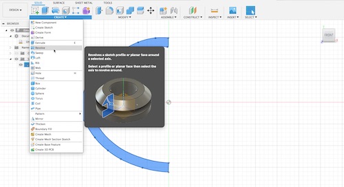
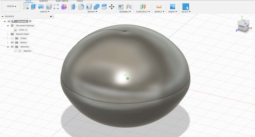
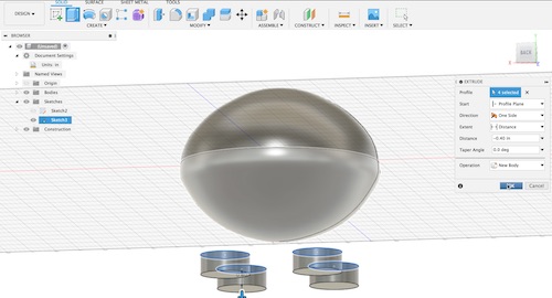
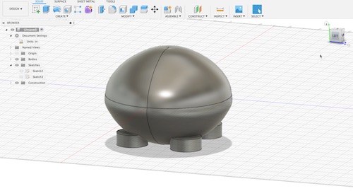
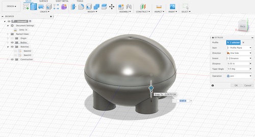
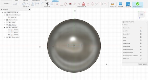
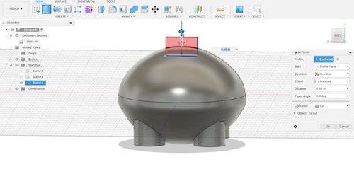
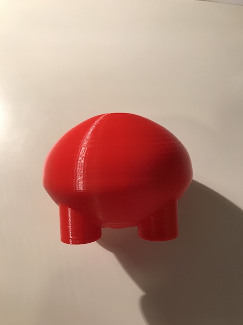
Key tools I used for this process include the Revolve tool, the Offset tool, the Offset Plane tool, and the Pull and Extrude tools. The Offset tool allowed me to use a fit point spline and make the inside layer of the exact same shape so that I was ultimately able to use the Revolve tool to rotate it and create the hollow shape I needed. I used the Extrude tool to make the slot for the coins, and to make the four legs the base sat on.

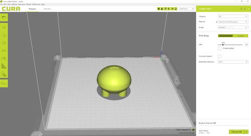
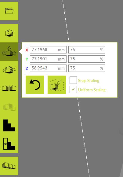
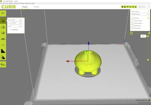
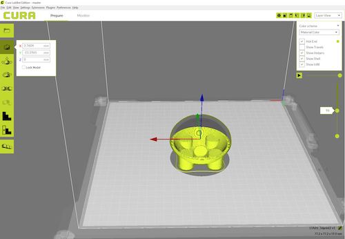
I saved my design as an STL file and opened it in the software we use for 3D printing Cura. I rotated my design and scaled it down to 75% to minimize the print time, which started at around 9h. I selected ‘Layer View’ so I could see how the piggy bank would print layer by layer. Initially, I saw that the legs were not long enough and also that the coin was too deep in the base. I altered my file and made a new STL file with the edits.
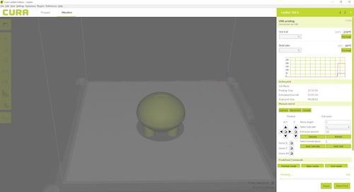
Here are the settings I used to 3D print my design. I used 20% infill for the PLA. The total time came down to 3h44min.
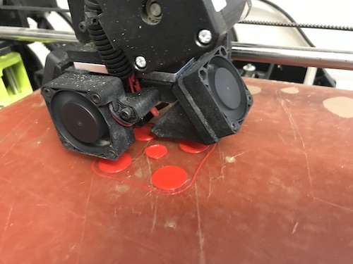
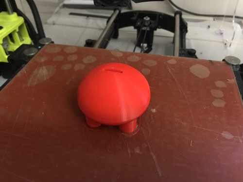
The 3D printer printed my design without any issues. I realized that because I had scaled down my design on Cura, I could only fit dimes and pennies into the piggy bank.
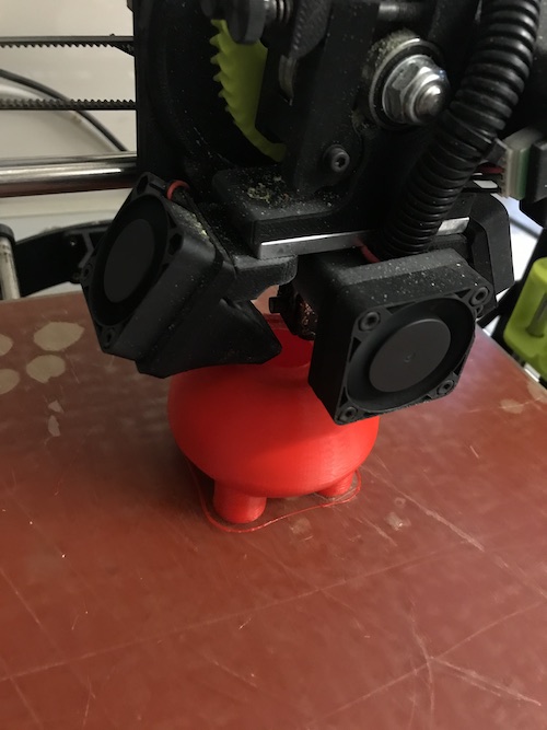
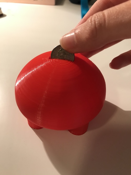
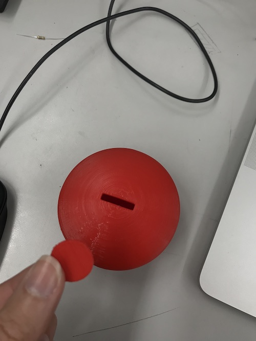
I used tweezers to dislodge the coin I had printed inside it, which I was even able to remove.
3D Scanning
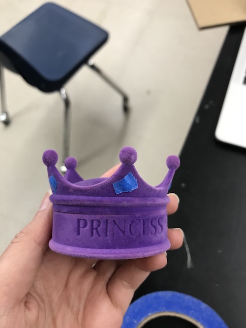
I decided to scan a cute crown I found from when I was younger (a part of which was broken but it’s fine).
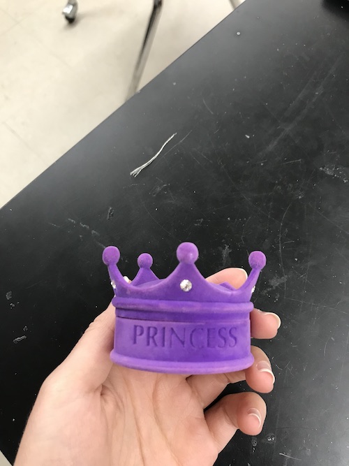
I had to put pieces of masking tape on the fake jewels because they would mess up the 3D scanner by reflecting the light.
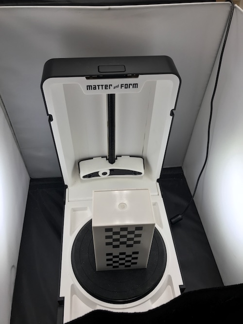
I used my lab’s Matter and Form 3D Scanner, and followed the instructions provided by the manual. After setting up the machine in the lighting booth, the first step was the calibrate it. I did so by opening the Matter and Form software, selecting Tools -> Calibration, and following the instructions.
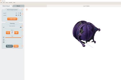
I then clicked File -> New, Point Cloud -> + New Scan to start scanning my object. I had to fiddle with the Geometry and Texture settings in order to generate the most precise and accurate scan possible. Here are the final settings I used:
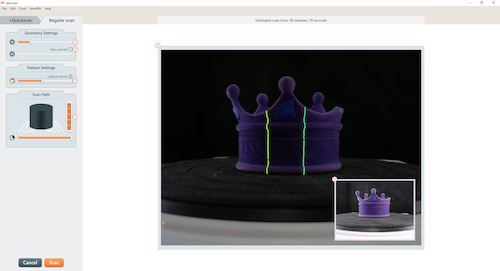
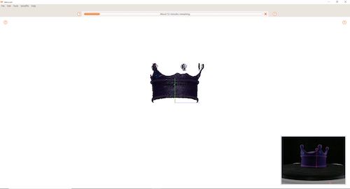
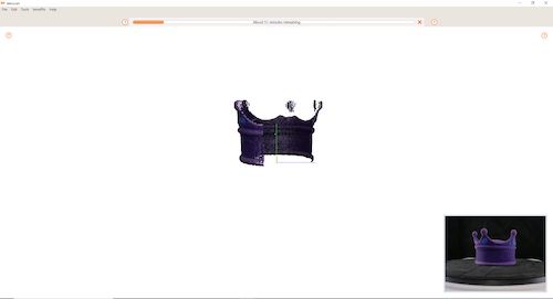
This scan alone took almost an hour. I realized I could have lessened the Scan Path setting because my object was small. I implemented this in my second scan, which cut down the scan time. You can see the progression of the scan below:
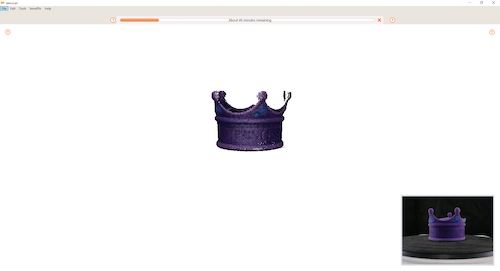
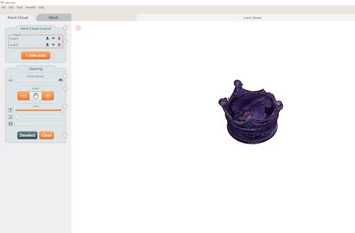
Here is my completed first scan:
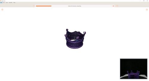
I decided to scan it again but change the angle, so more of the top of the crown could be filled in. This is my completed second scan:
In order to combine the two scans, I clicked the ‘A’ for Align next to my second scan, which I renamed.
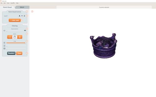
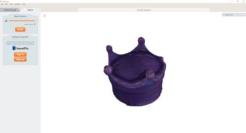
I decided these two scans were sufficient, and I could proceed to cleaning up the points and meshing the scans. First I used the ‘Noise Selection’ tool to clean up the immediate outer points. I then used the ‘Brush’ tool and manually subtracted points with a little more precision.

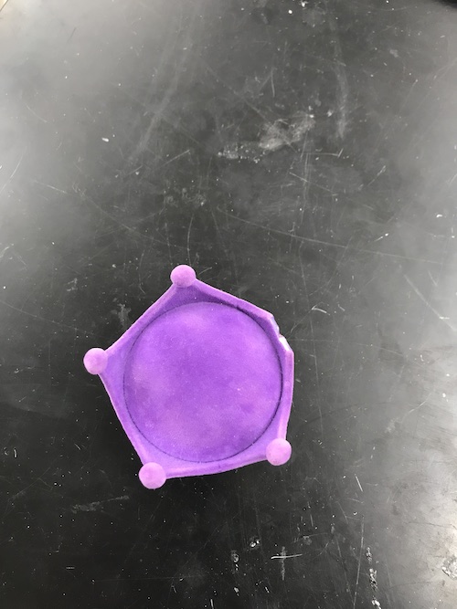
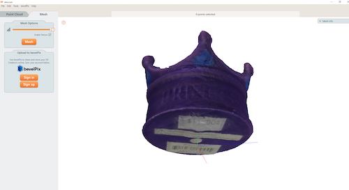
I then selected ‘Mesh’ and set the slider all the way to the right so it would be high detail. I also made sure to select the ‘Enable Texture’ box. Here is my final meshed scan. It actually turned out pretty well, and you can see the slight “PRINCESS” outline along with the labels on the bottom of the crown.
To download my files for this week, click here.
Group Assignment
The group assignment for this week was to characterize the design rules of our 3d printer. We learned about the overhang, bridges, clearance, dimension, surface finish, infill, anisotropy, and wall thickness specs of our Lulzbot Mini 3D Printer. You can view my group’s process on our group page here.
I contributed to this assignment but helping define the aforementioned terms, downloading the STL files provided by Neil and assorting them to 3D printers, and interpreting and documenting our results. This assignment showed our 3D printer’s ability to print angles and bridges without supports, how well it finishes different surfaces, and more. I also learned the ideal infill for prints.