Charlotte Latin 2020 Week 5 Group Assignment
3D Scanning and Printing
Characterizing the 3D printer
For the group project this week, we characterized the design rules for the 3D printing process: overhang, bridges, clearance, dimension, surface finish, infill, anisotropy, and wall thickness.
Concept Definition
We first tried to figure out what each of these terms meant. After that, we came up with a plan to measure each of the things we needed to.
| Term | Meaning | |
|---|---|---|
| Overhang | Any part of a print that extends outward, beyond the previous layer, without any direct support. | Source |
| Bridges | An extrusion of material that horizontally links two raised points. Note that obviously, design considerations need to be made if the bridge stretches across a very high amount and is at a very sharp angle, which we will be considering here. | Source |
| Clearance | How many units your object may differ from the intended dimensions (i.e. + - .01mm on a cube intended to be 20x20 mm could print as 20.01mm x 20.01mm… etc.) | Source |
| Dimension | Dimension - The three measurable coordinates in a print (X, Y, Z). | Source |
| Surface Finish | A technique that turns a raw 3D printed part into a finished product. | Source |
| Infill | A repetitive structure used to take up space inside an otherwise empty 3D print. infill is typically hidden from view, but occasionally, special infill patterns are not. | Source |
| Anisotropy | The property of being directionally dependent and having different properties when measured along axes in different directions. | Source |
| Wall Thickness | The width of the designs that are printed. Note: you need to make sure the thickness of the pieces aren't so small that you end up with holes in your material or easily snappable parts (however, the weakness can be counteracted with infill and other types of settings). |
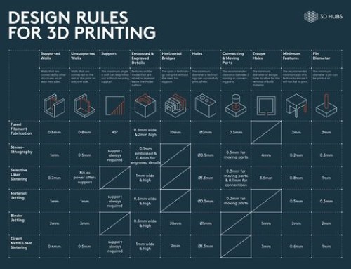
Here is a Design Rules sheet that covers all the above.
Loading Our Files
We first downloaded the nine suggested files from the Fab Academy page as STL's.
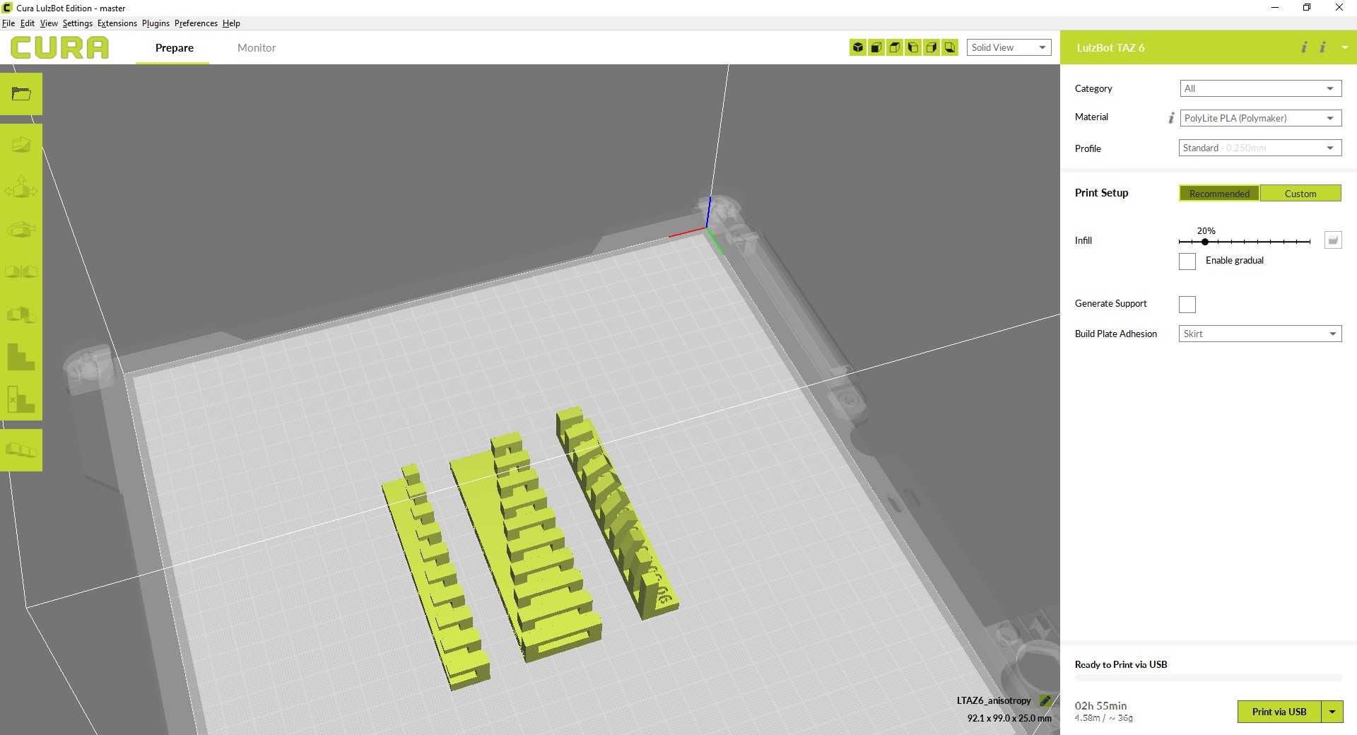
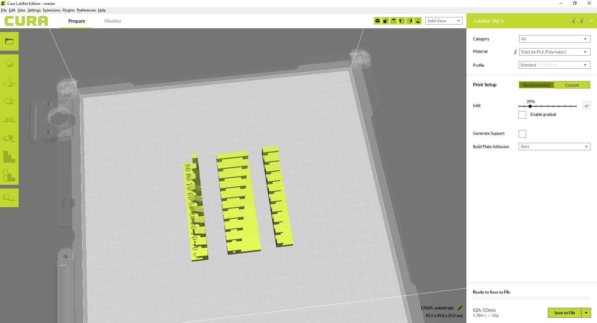
Then we imported them into Cura, the program our lab uses to send files to the printer. Our lab has multiple printers, so we used three printers to print the files. We first started under the Prepare section. For each print, after we imported the file, we kept the Category as "All", set the Material to "PolyLite PLA (Polymaker)", and the profile to "Standard". Under the Print Setup section, we clicked on the Recommended rectangle. We set the infill slider to 20%. We added supports for the tests that needed them, and we left supports out for the tests that didn't.
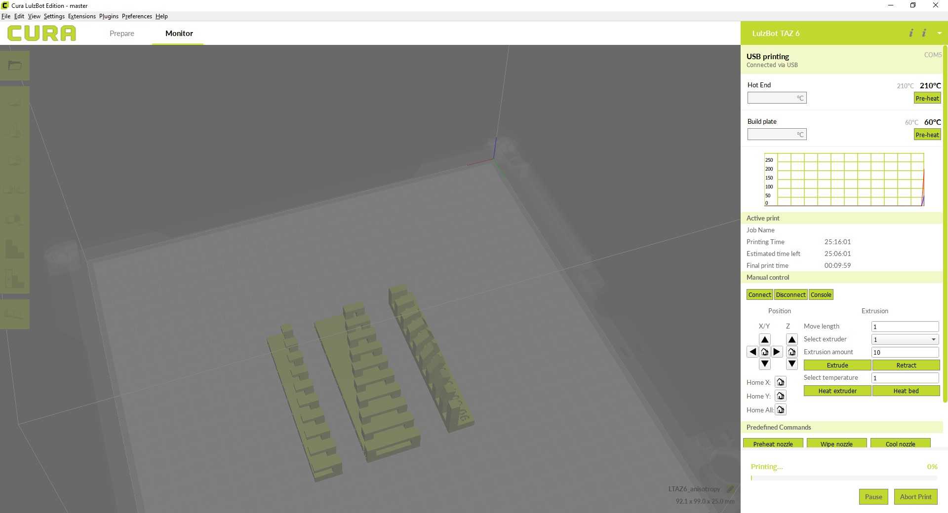
These are the pictures for the file of parts that require supports (the file includes the extra parts, like the infill, surface finish, dimensions, and anisotropy parts).
These are the pictures for the file of parts that do not require supports: the angle, overhang, and bridging parts.
Printing Procedure
- Upload files and change settings as specified above.
- Preheated the bed and nozzle. The settings needed are on the side of the ring of filament being used.
- Put PLA in the printer.
- Make sure PLA is in properly by hitting extrude. Use tweezers to remove the extrusion.
- Click Print
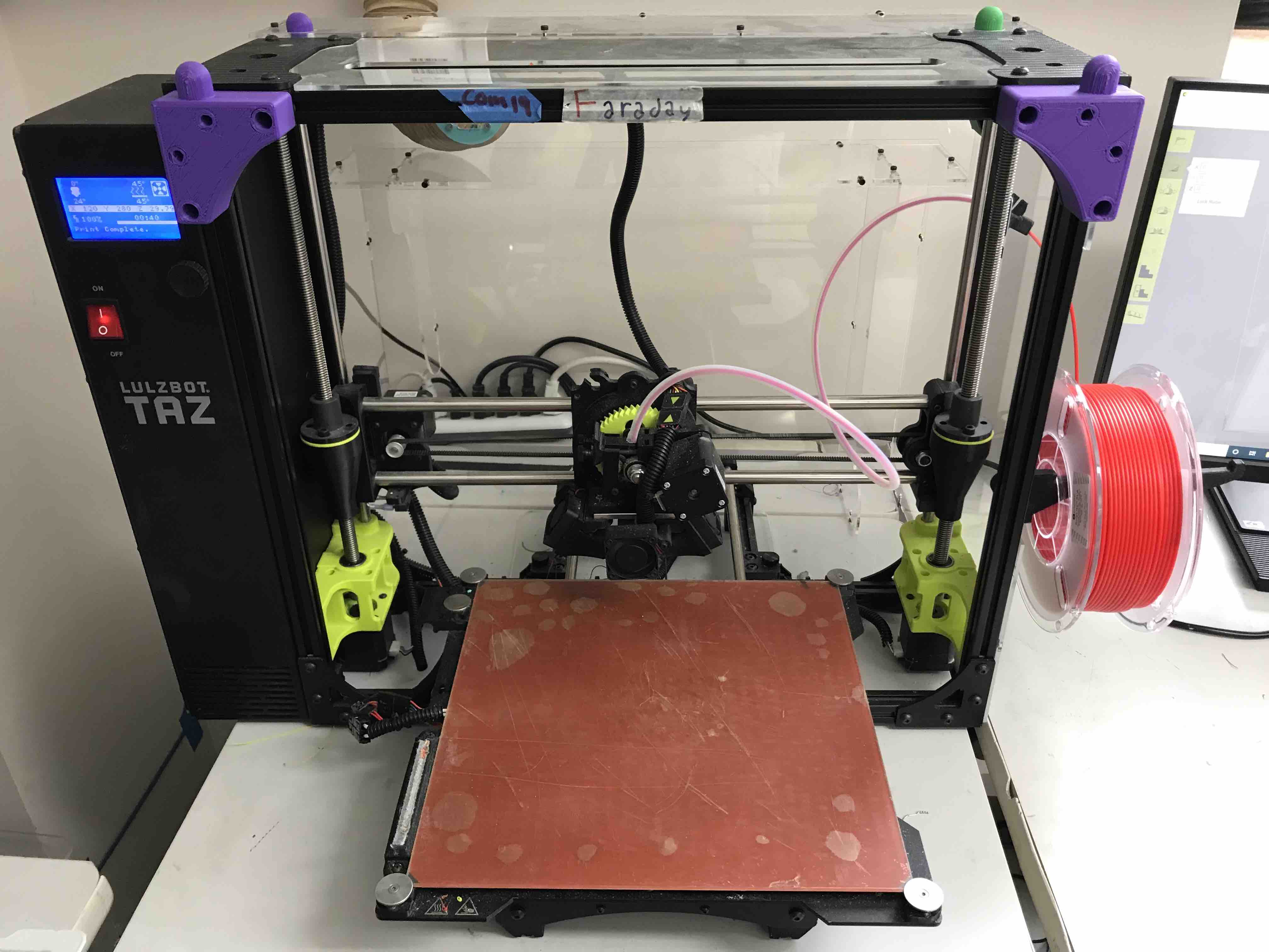
We started the print out on our lab's Lulzbot Mini 3D printer. We all have experience using 3D printers from other classes, so this was not too difficult. We are using FFF (Fused Filament Fabrication), which is done by melting plastic filament and dragging a printer nozzle across a bed to place the filament. The printed file is sliced into thin layers, and the printer interprets code to know where/how these layers need to be placed. The settings we made adhered to what we mentioned above. We didn't use supports on any of the files except the Lulzbot Mini 3D printer and the "clearance" file, to purposefully show what the effects of supports are on the files.
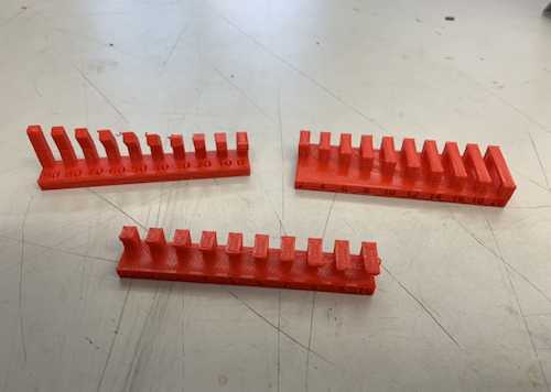
The prints that did not need supports looked like this.
Supports pose a challenge in the fact that it is difficult to remove them once the print is over. Typically, you have to use a sharp object of some sort to remove them, which can be tricky. We decided to use this method. We used needle nosed pliers to extract the supports from each of the models (clearance and overhang) once we had printed them.
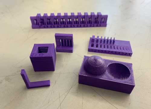
Results
The overhang print with supports showed our 3D printer's ability to print objects at 90 degree angles. The clearance print with supports showed the minimal distance that allows the parts to spin on the rod. We saw that the clearance of our 3D printer was .4 mm.
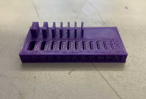
The angle print revealed the minimum angle our 3D printer was able to print without supports. Our 3D printer successfully printed each of the overhangs up until 40 degrees.
The overhang print without supports demonstrated the maximum length our 3D printer could print 90˚ overhangs without supports. We found that our 3D printer could barely print 2mm (insert unit of measurement) successfully.
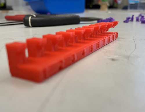
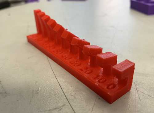
The bridge print showed the extent of our 3D printer's ability to 3D print different lengths of bridges without supports. Our 3D printer was able to print up to the last measure, 20mm long, with minimal distortion.
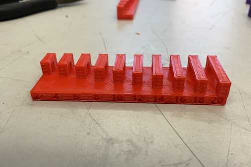
The wall thickness print revealed the minimum wall width our 3D printer could print. Our 3D printer successfully made it to approximately 10mm.
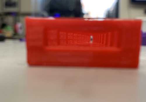
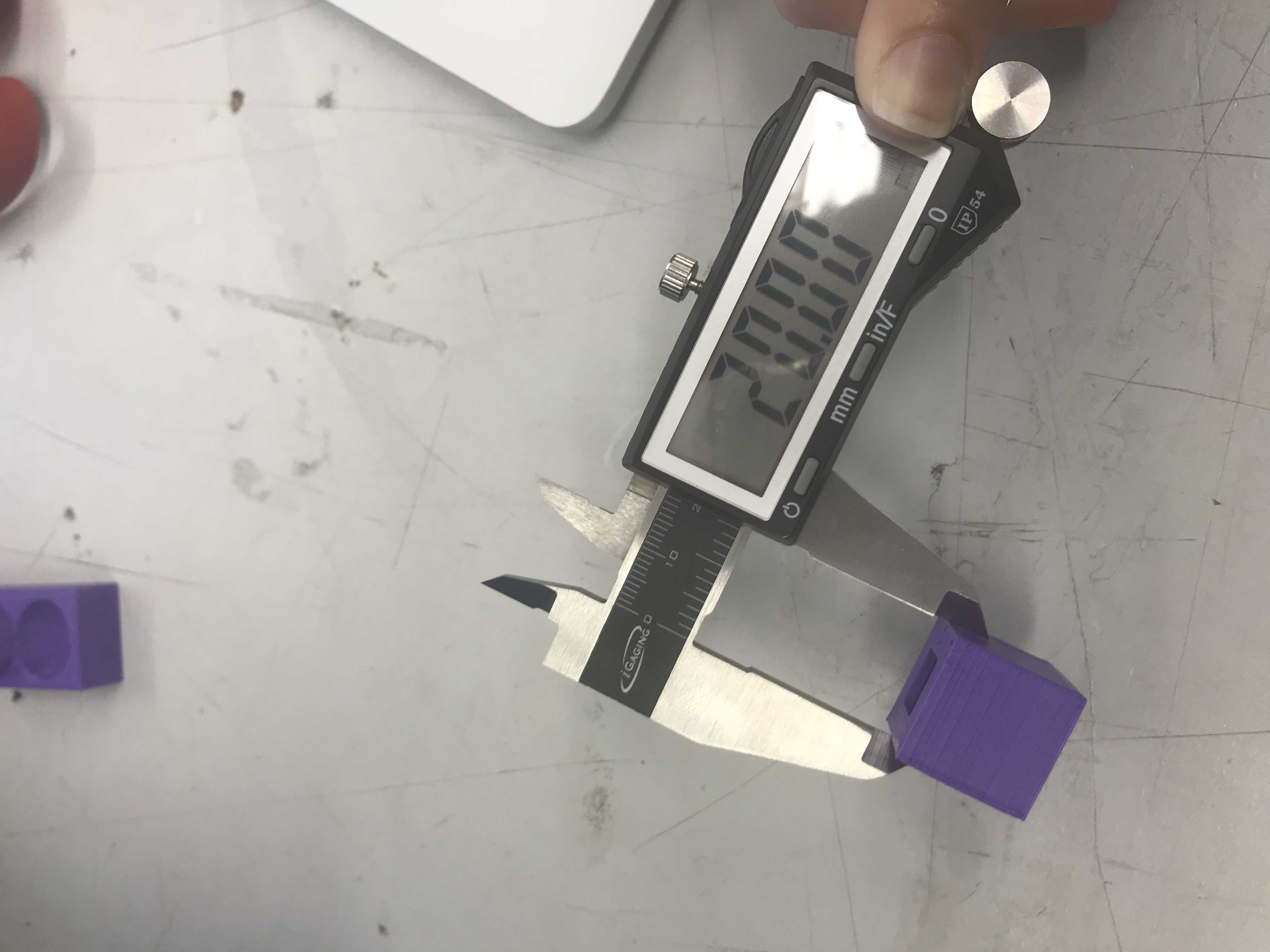
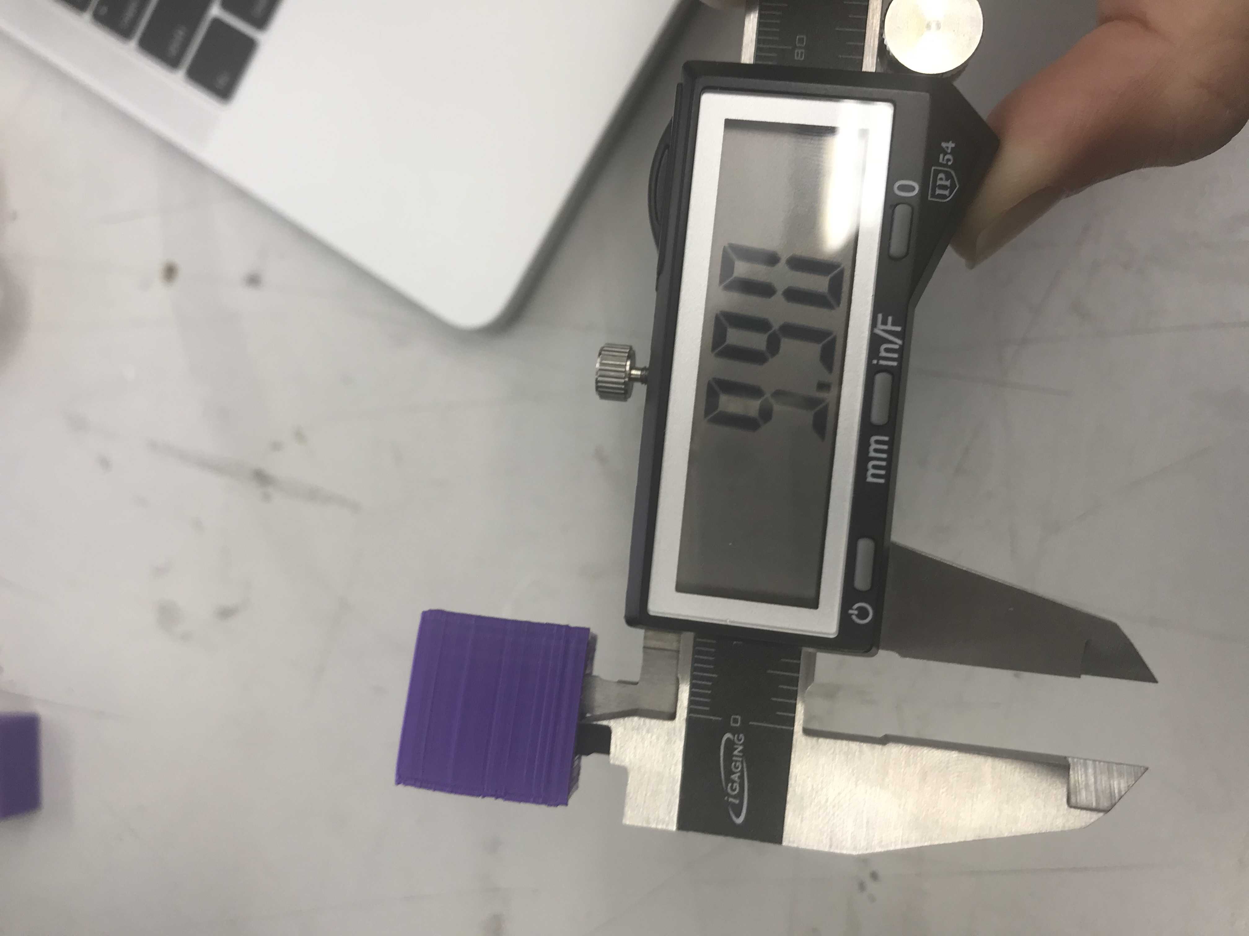
The dimensions print showed us the difference between what is designed and what is actually printed. The inner square was supposed to be 10mm wide, and the outer square was supposed to be 20mm wide. However, the inner square was 9.9mm wide, but the outer square was 20mm wide.
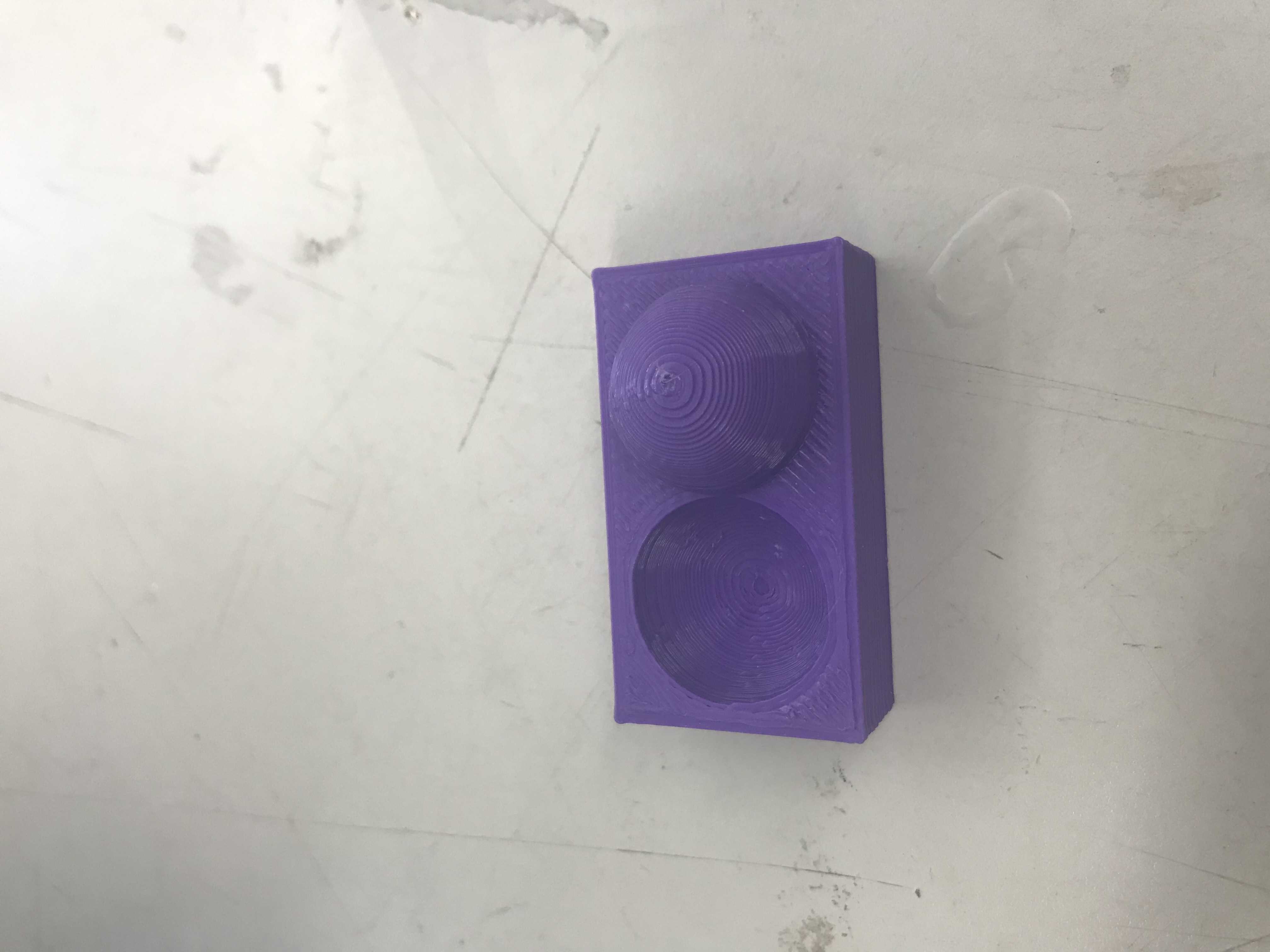
The surface finish print showed us that the 3D printer can do a rather good job smoothing out curved surfaces, although it does a better job at smoothing out indented curved surfaces (like holes) than raised surfaces. On the semi-sphere, each layer is rather visible, but it looks smooth from afar.
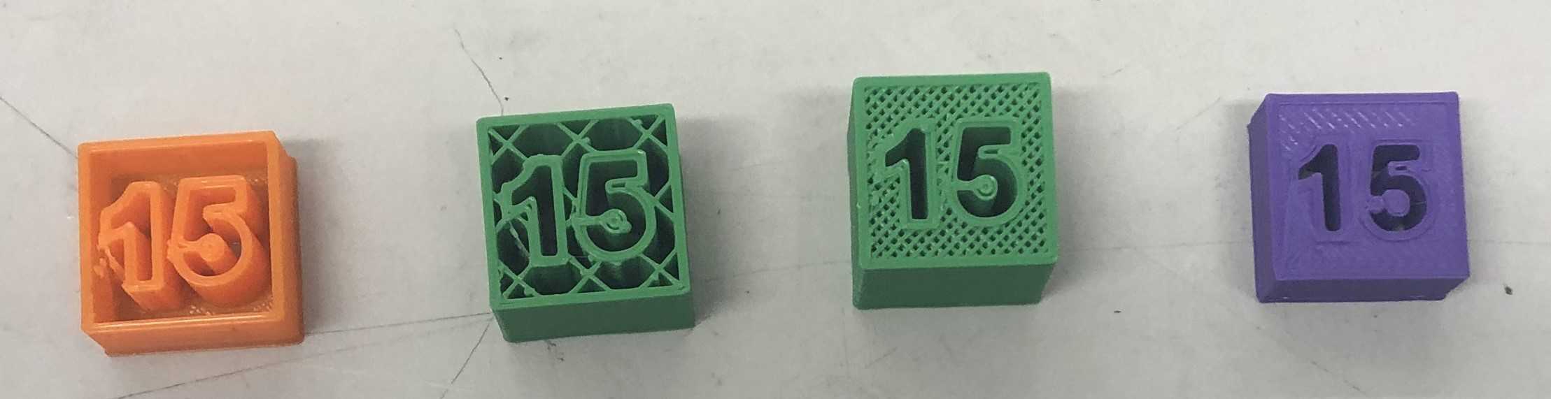
We did four infill prints: 0%, 20%, 50%, and 100%. 0% did not fill in the print at all while 100% completely filled in the print. Print a variety of infills displayed the quality of the print in accordance with the time it took to print. Printing the design with 0% infill was quick but flimsy, while 100% infill took awhile and was very solid. We found that the ideal infill level was 20%, because it lessened the print time while optimizing PLA usage and created a successful and light print.