5. Electronic Production
1. Assignment && week workflow planning
- Group
characterize the design rules for your PCB production process
- Individual
make an in-circuit programmer by milling and stuffing the PCB, test it, then optionally try other PCB processes
2. How i did it
2.0 HeroShot of the week
2.1 My working progress
- Characterize the design rules
My group assignment actually is also my individual assignment, as our lab has only me as Fab 2020 student :) Anyway let me get started
Luckily it is not too difficult for me to understand roughly about a PCB production process, as i’m working at Seeed(which Neil also introduced as a board house. Well not exactly accurate definition of the entire business but we do have this business unit). We have an 43 pages DFM handbook, online(Also hardcopy available) available, also translated to different languages other than English, Japanese, French, German, Russian, Portuguese, etc.

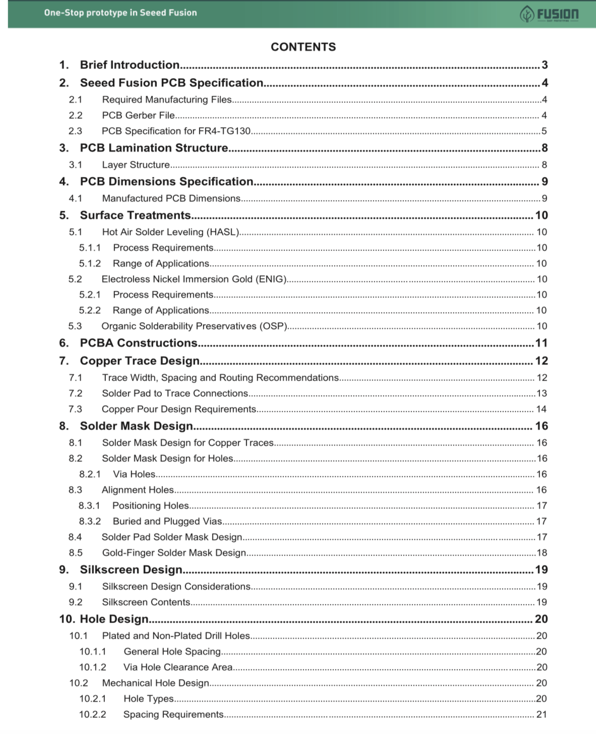
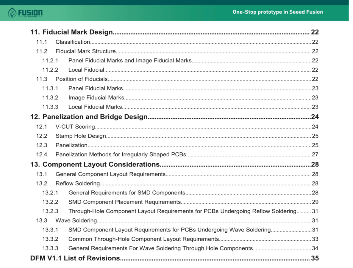
Find the SeeedFusion_DFM here.

The usual way we do mass production of PCB, not using milling machines but etching machines. The process looks like following(in short) -
Design files ready -> Check the design -> Film -> film on FR4(inner layer) -> etching -> Film strip -> inspection -> PP & other layers(outter layers) -> repeat from Film step to strip step -> drilling -> plating -> Inspection.
However from Fab Academy i’m not following the above process, as i’m doing only several boards instead of mass production. I’m using a milling machine instead.
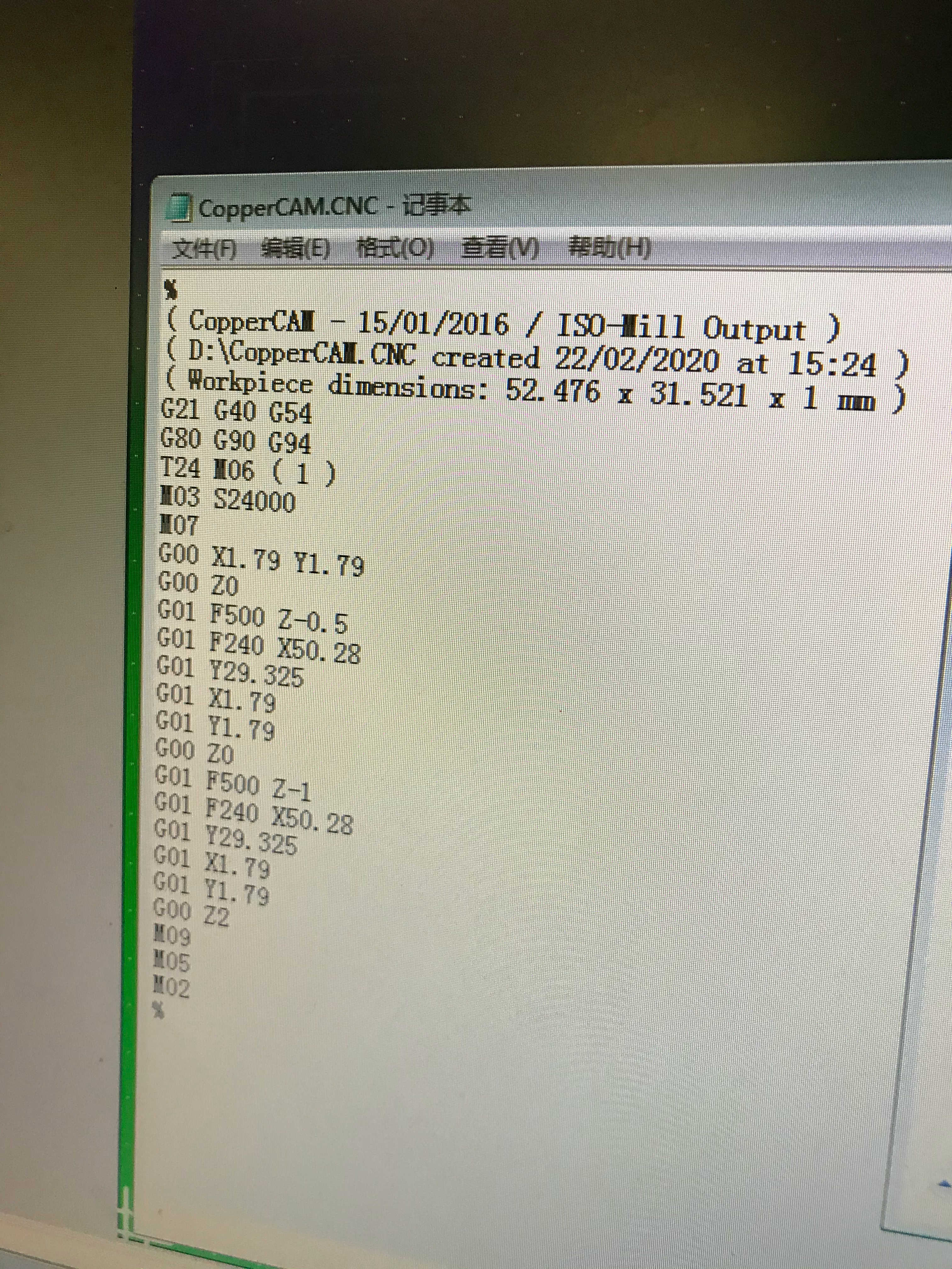
I was using a made-in-China milling machine “JINGYAN”. It reads G code. The CAM software also comes with the machine “CopperCAM”.
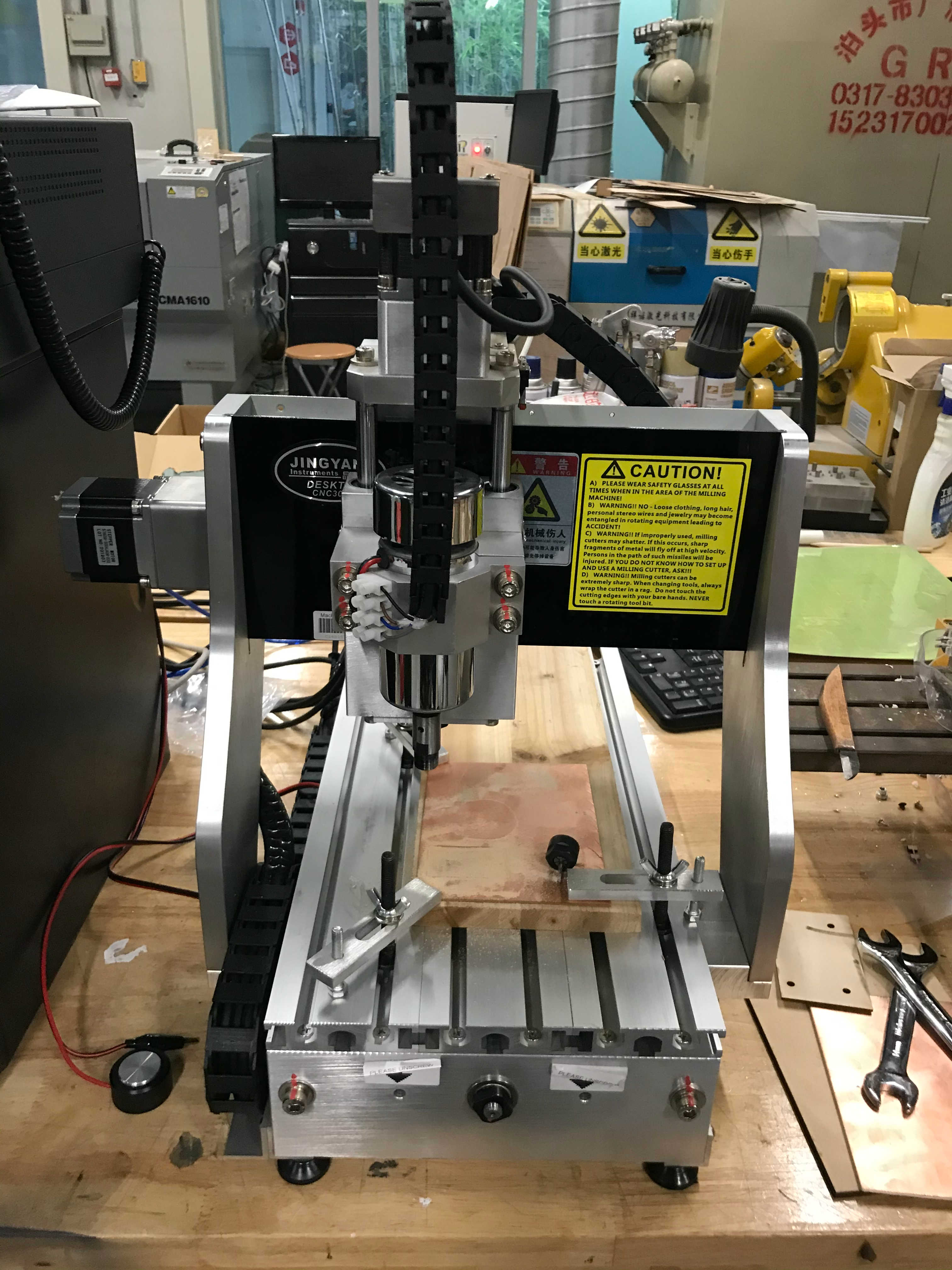
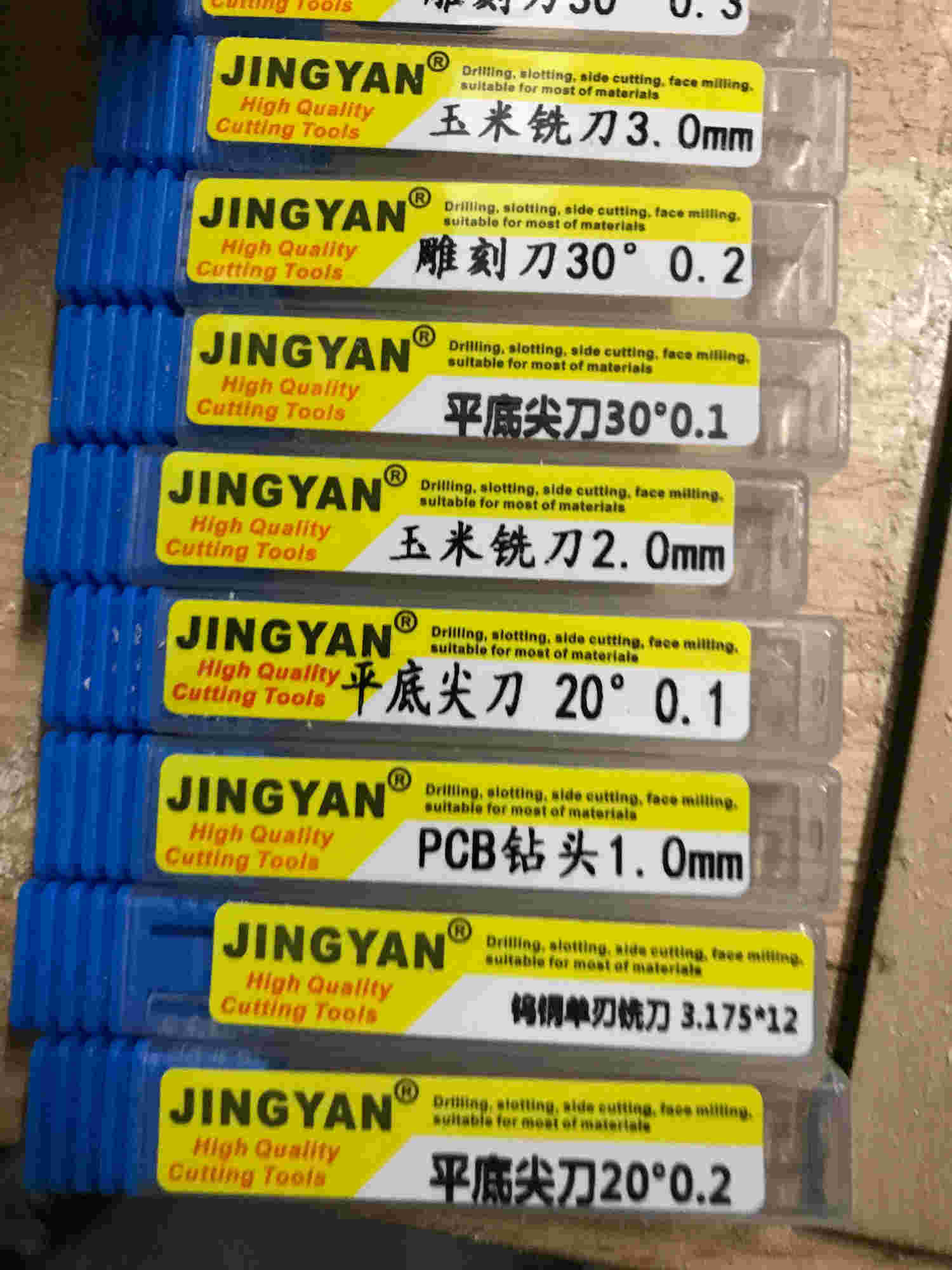
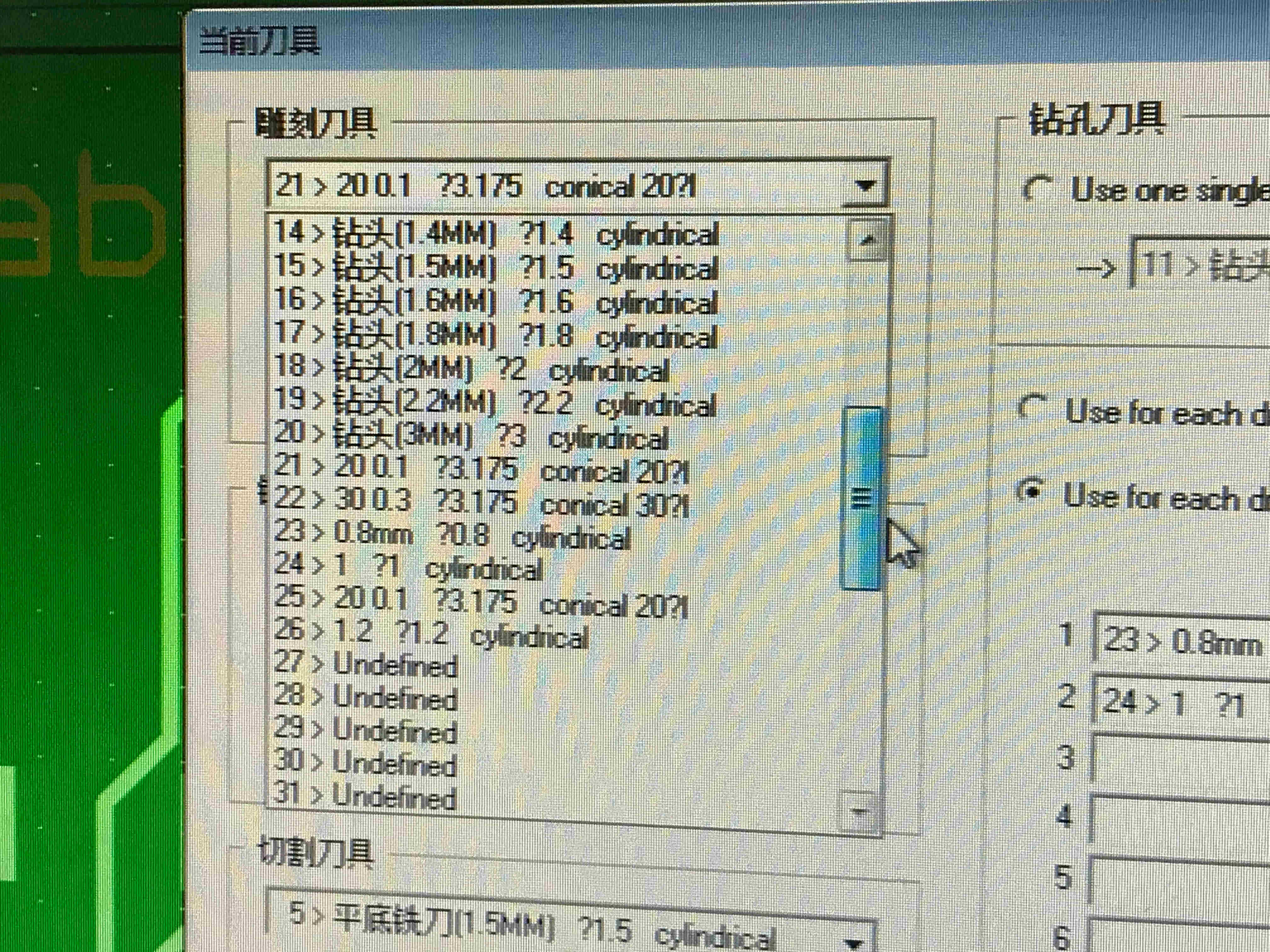
The tools that in the lab we had
Thickness of the copper board : 1.6mm, which means the maximum cutting depth should be no more than 1.6mm - below are the parameters set to the Mods.
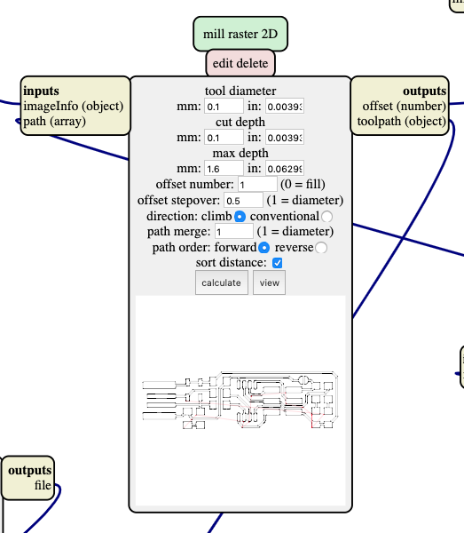
The design rules will be: having a design file ready, go to CopperCAM, and generate Gcodes. Then adjusting the milling machine, by making the Copper board stays flat, Selecting the machining tools, checking the focus, zeroing the tool, everything ready and start milling the different layers with changing tools in the between.
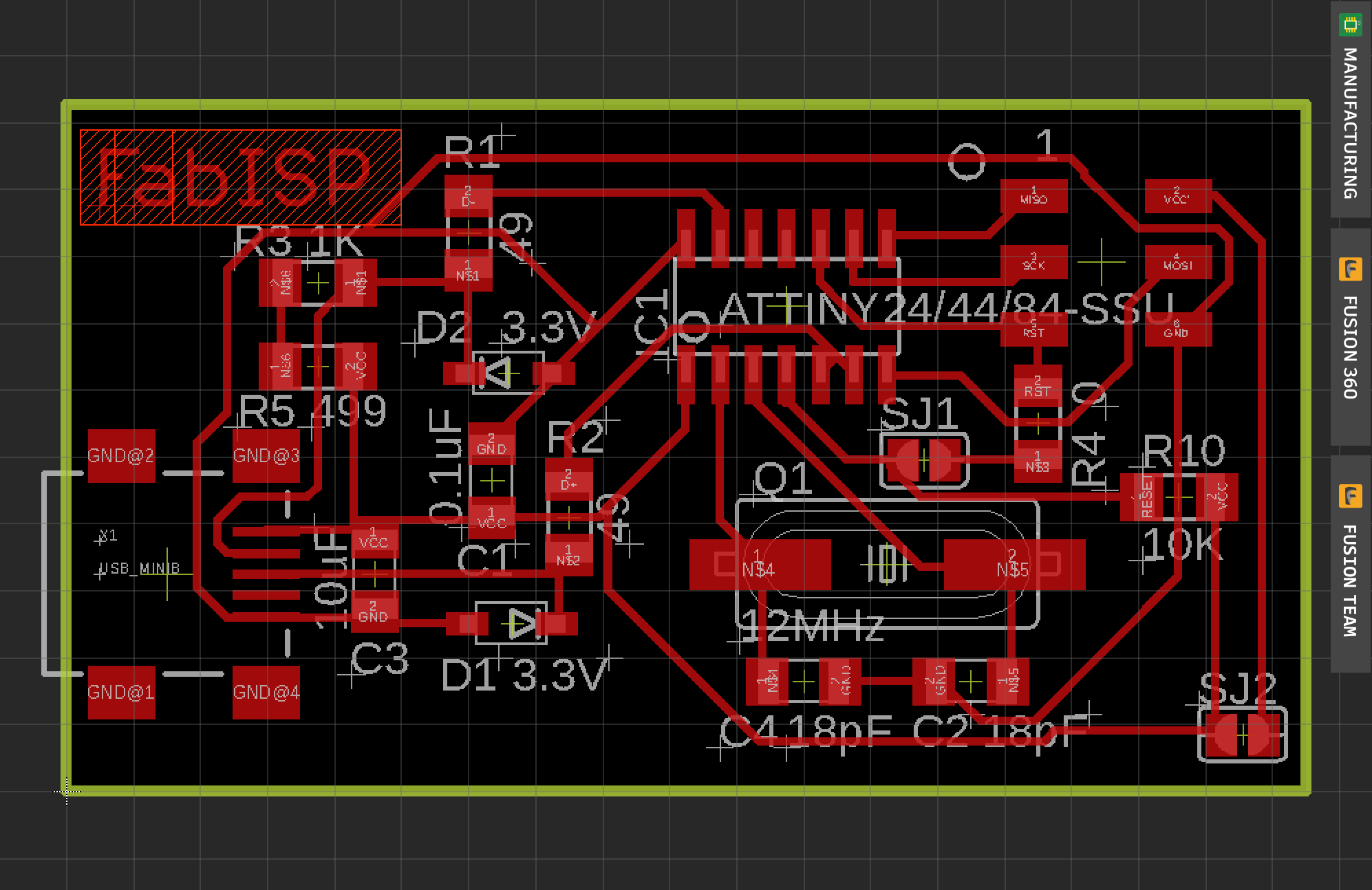
- Eagle
Got 2 files from my local instructor, designed originally by Neil.
One was .brd while another it was .sch. To my understanding the .sch was the schematic while another was the layout

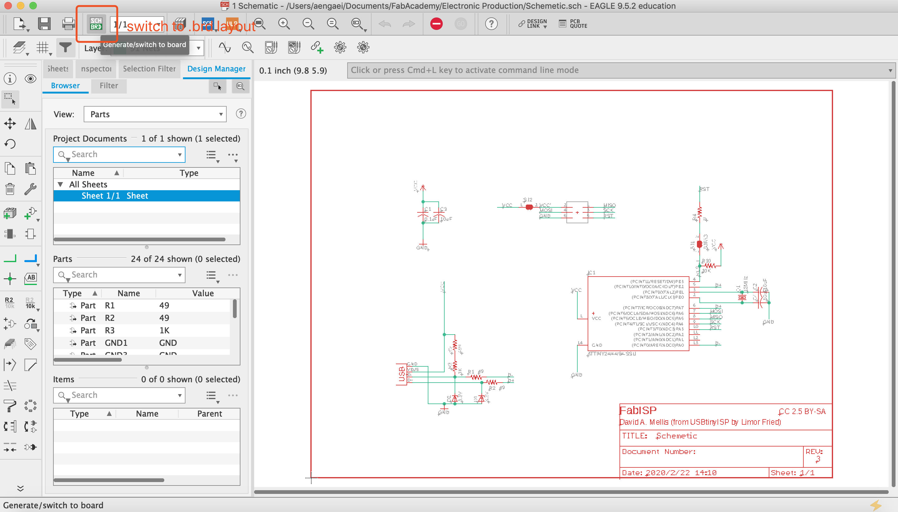
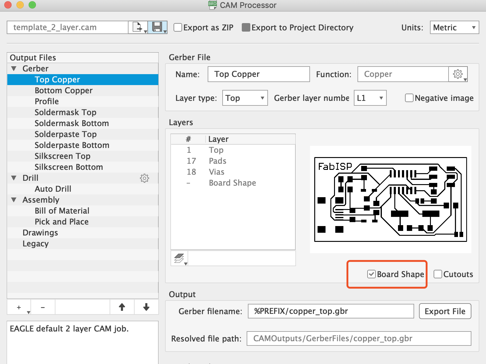
By click the ‘manufacturing’ button on upper right corner i will be able to export this layout to a gerber file, by clicking the ‘CAM’ button. The gerber file will include all the layers that needed to be manufactured - Top Copper, Bottom Copper, etc.
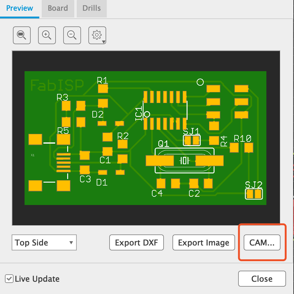
Now i have all the gerber files ready. Copying the gerber files to an USB Drive and then i carried it to another step.
- CAM_CopperCAM
The CAM software i was using was not Mods or Fabmodule, but using gerber files and use CopperCAM as the CAM software.
Animate the final board looks by selecting different tools
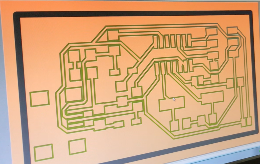
The CAM tool can generate and export Gcode for milling
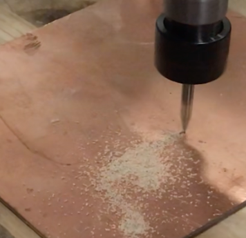
- Milling Machine
Tools
0.1mm concial20 degree for milling the trace, 0.2mm 20 degree
1mm For cutting the edge
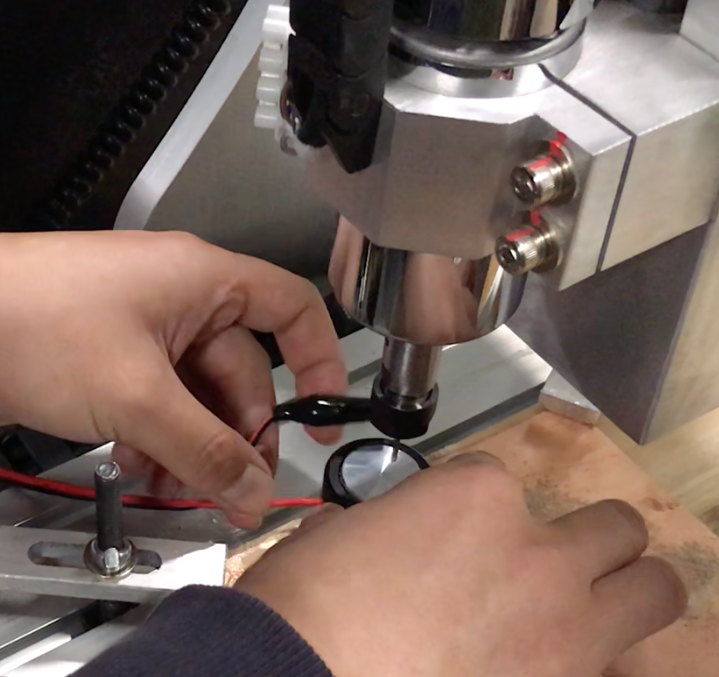
Zeroing, 29.5cm,
Focus,
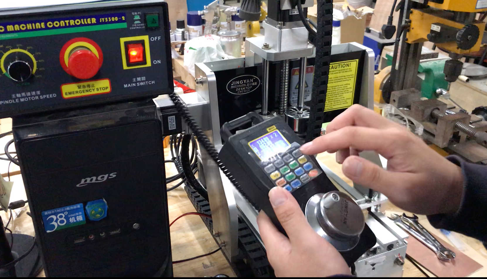
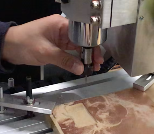
Start milling
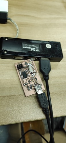
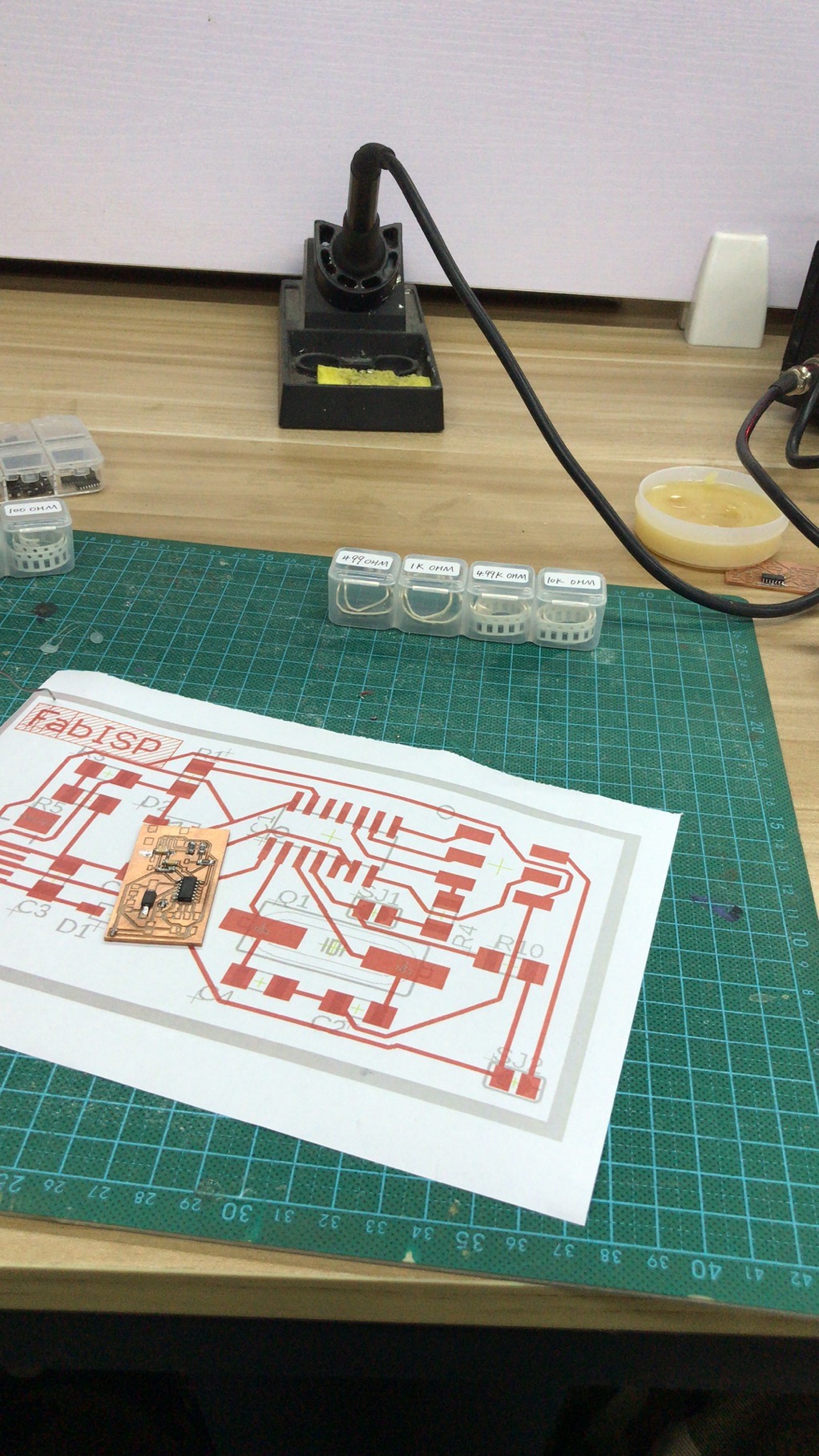
- Soldering
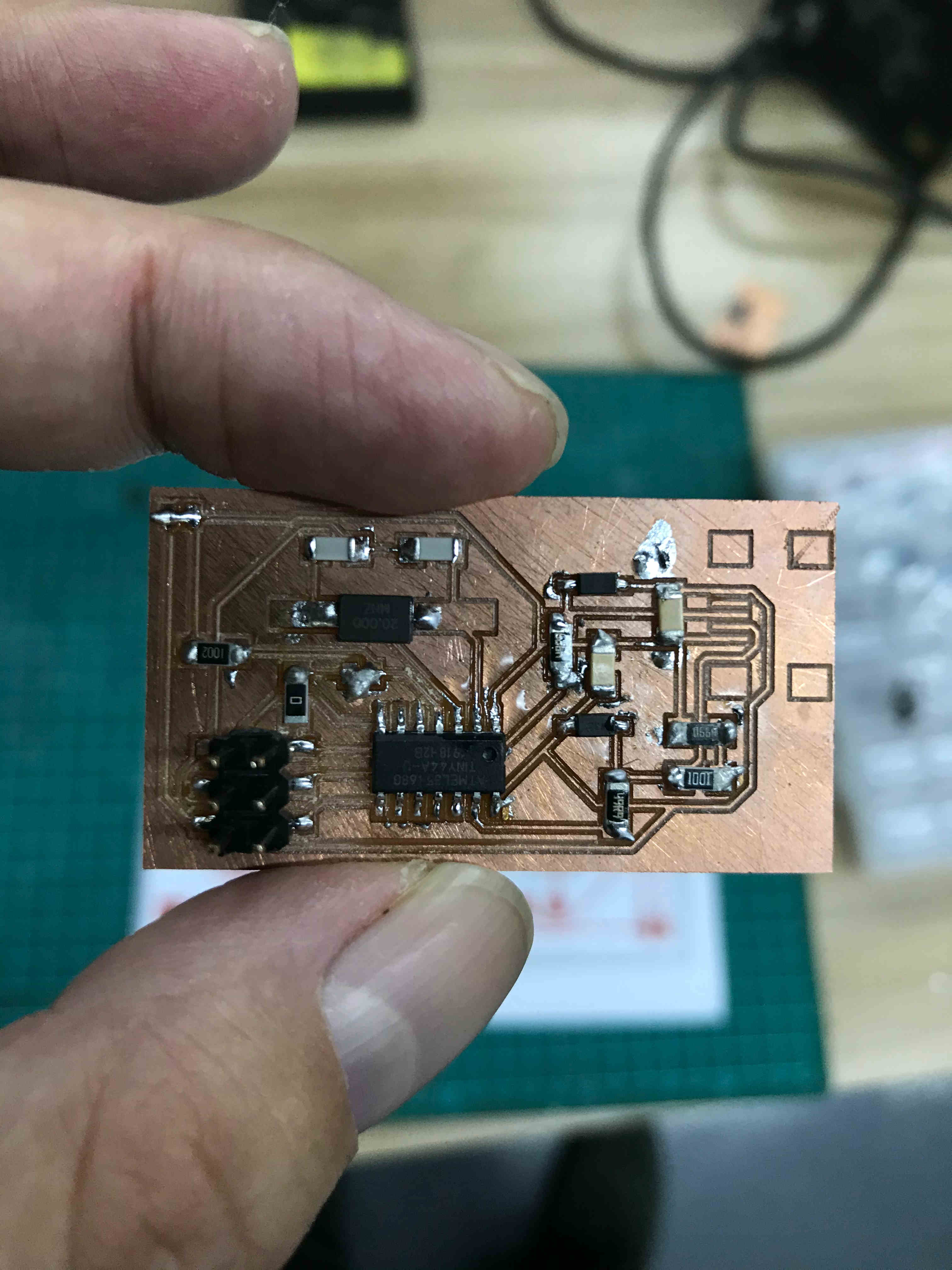
Picking the materials i would be using, the list of parts i would be using and getting soldering iron, solder wire and flux ready start soldering.
It took me one hour to solder and finally done. Checked with multimeter and there were no open circuits or short circuits which was perfect.
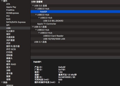
- Testing
Download the environment - Crosspack
Download Xcode Download firmware source code
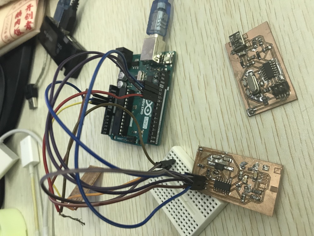
I was not using another FabISP board but instead an Arduino as the programmer.
CD into the source code directory and run
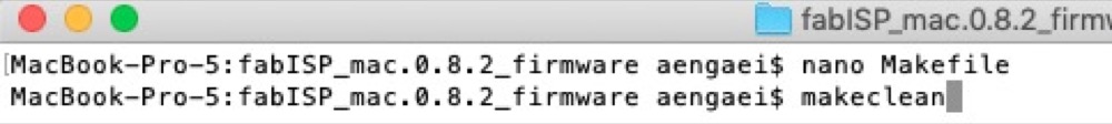
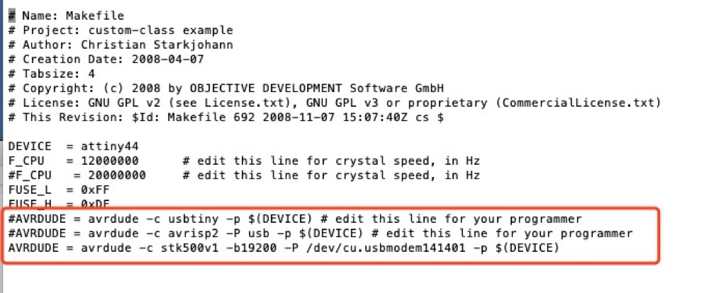
Edited the makefile
Running the programming tutorials and it was all successful!
make clean
maker hex
make fuse
make program
➜  fabISP_mac.0.8.2_firmware make clean
rm -f main.hex main.lst main.obj main.cof main.list main.map main.eep.hex main.elf *.o usbdrv/*.o main.s usbdrv/oddebug.s usbdrv/usbdrv.s
➜  fabISP_mac.0.8.2_firmware make hex
avr-gcc -Wall -Os -DF_CPU=20000000  -Iusbdrv -I. -DDEBUG_LEVEL=0 -mmcu=attiny44 -c usbdrv/usbdrv.c -o usbdrv/usbdrv.o
avr-gcc -Wall -Os -DF_CPU=20000000  -Iusbdrv -I. -DDEBUG_LEVEL=0 -mmcu=attiny44 -x assembler-with-cpp -c usbdrv/usbdrvasm.S -o usbdrv/usbdrvasm.o
avr-gcc -Wall -Os -DF_CPU=20000000  -Iusbdrv -I. -DDEBUG_LEVEL=0 -mmcu=attiny44 -c usbdrv/oddebug.c -o usbdrv/oddebug.o
avr-gcc -Wall -Os -DF_CPU=20000000  -Iusbdrv -I. -DDEBUG_LEVEL=0 -mmcu=attiny44 -c main.c -o main.o
main.c:88:13: warning: always_inline function might not be inlinable [-Wattributes]
 static void delay ( void )
             ^~~~~
avr-gcc -Wall -Os -DF_CPU=20000000  -Iusbdrv -I. -DDEBUG_LEVEL=0 -mmcu=attiny44 -o main.elf usbdrv/usbdrv.o usbdrv/usbdrvasm.o usbdrv/oddebug.o main.o
rm -f main.hex main.eep.hex
avr-objcopy -j .text -j .data -O ihex main.elf main.hex
avr-size main.hex
   text    data     bss     dec     hex filename
      0    1968       0    1968     7b0 main.hex
➜  fabISP_mac.0.8.2_firmware make fuse
avrdude -c stk500v1 -b19200 -P /dev/cu.usbmodem14401 -p attiny44 -U hfuse:w:0xDF:m -U lfuse:w:0xFF:m

avrdude: AVR device initialized and ready to accept instructions

Reading | ################################################## | 100% 0.02s

avrdude: Device signature = 0x1e9207 (probably t44)
avrdude: reading input file "0xDF"
avrdude: writing hfuse (1 bytes):

Writing | ################################################## | 100% 0.01s

avrdude: 1 bytes of hfuse written
avrdude: verifying hfuse memory against 0xDF:
avrdude: load data hfuse data from input file 0xDF:
avrdude: input file 0xDF contains 1 bytes
avrdude: reading on-chip hfuse data:

Reading | ################################################## | 100% 0.01s

avrdude: verifying ...
avrdude: 1 bytes of hfuse verified
avrdude: reading input file "0xFF"
avrdude: writing lfuse (1 bytes):

Writing | ################################################## | 100% 0.01s

avrdude: 1 bytes of lfuse written
avrdude: verifying lfuse memory against 0xFF:
avrdude: load data lfuse data from input file 0xFF:
avrdude: input file 0xFF contains 1 bytes
avrdude: reading on-chip lfuse data:

Reading | ################################################## | 100% 0.01s

avrdude: verifying ...
avrdude: 1 bytes of lfuse verified

avrdude: safemode: Fuses OK (E:FF, H:DF, L:FF)

avrdude done.  Thank you.

➜  fabISP_mac.0.8.2_firmware make program
avrdude -c stk500v1 -b19200 -P /dev/cu.usbmodem14401 -p attiny44 -U flash:w:main.hex:i

avrdude: AVR device initialized and ready to accept instructions

Reading | ################################################## | 100% 0.02s

avrdude: Device signature = 0x1e9207 (probably t44)
avrdude: NOTE: "flash" memory has been specified, an erase cycle will be performed
         To disable this feature, specify the -D option.
avrdude: erasing chip
avrdude: reading input file "main.hex"
avrdude: writing flash (1968 bytes):

Writing | ################################################## | 100% 2.80s

avrdude: 1968 bytes of flash written
avrdude: verifying flash memory against main.hex:
avrdude: load data flash data from input file main.hex:
avrdude: input file main.hex contains 1968 bytes
avrdude: reading on-chip flash data:

Reading | ################################################## | 100% 1.40s

avrdude: verifying ...
avrdude: 1968 bytes of flash verified

avrdude: safemode: Fuses OK (E:FF, H:DF, L:FF)

avrdude done.  Thank you.

avrdude -c stk500v1 -b19200 -P /dev/cu.usbmodem14401 -p attiny44 -U hfuse:w:0xDF:m -U lfuse:w:0xFF:m

avrdude: AVR device initialized and ready to accept instructions

Reading | ################################################## | 100% 0.02s

avrdude: Device signature = 0x1e9207 (probably t44)
avrdude: reading input file "0xDF"
avrdude: writing hfuse (1 bytes):

Writing | ################################################## | 100% 0.01s

avrdude: 1 bytes of hfuse written
avrdude: verifying hfuse memory against 0xDF:
avrdude: load data hfuse data from input file 0xDF:
avrdude: input file 0xDF contains 1 bytes
avrdude: reading on-chip hfuse data:

Reading | ################################################## | 100% 0.01s

avrdude: verifying ...
avrdude: 1 bytes of hfuse verified
avrdude: reading input file "0xFF"
avrdude: writing lfuse (1 bytes):

Writing | ################################################## | 100% 0.01s

avrdude: 1 bytes of lfuse written
avrdude: verifying lfuse memory against 0xFF:
avrdude: load data lfuse data from input file 0xFF:
avrdude: input file 0xFF contains 1 bytes
avrdude: reading on-chip lfuse data:

Reading | ################################################## | 100% 0.01s

avrdude: verifying ...
avrdude: 1 bytes of lfuse verified

avrdude: safemode: Fuses OK (E:FF, H:DF, L:FF)

avrdude done.  Thank you.
3. Problems Occurred & Solutions
3.1 I broke 2 tools during the process
- When i was adjusting the Zeroing, i forgot to snap the negative side to the tool. The tool touched the hard surface and with nonstop then trying to go deeper - And it broke.
3.2 How to tell the orientation of the diodes?
- The zener diodes are marked, both in the drawing and on the packages, with a line on the cathode side.