7. Electronics design
1. Assignment && week workflow planning
1.1 Assignment requirements:
- individual
redraw an echo hello-world board, add (at least) a button and LED (with current-limiting resistor), check the design rules, make it, and test it
- Group
use the test equipment in your lab to observe the operation of a microcontroller circuit board
2. How i did it
2.0 HeroShot of the week
- The ATtiny44 board
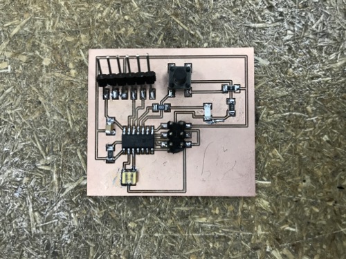
- Instead of making the board echoing ‘hello world’, i made the board with LED blinking controlled by the button
2.1 Group project
-
I only used the Multimeter after milling the board and stuffing the board.
After milling the board, i used the meter to test if there were traces been unintended open. I used the osciliscope to test the circuit in my further week - InputDevices -
After stuffing the board, i used the meter to test if theres were any short or open circuit.
2.2 Pick a board
-
Pick a microcontroller circuit board that i wanted to build, i picked ATtiny44.
-
The BoM of the board that i made
| Name | Qty |
|---|---|
| Attiny44 | 1 |
| 10k ohm resistor | 2 |
| 0 ohm resistor | 1 |
| 1uF capacitor | 1 |
| 20Mhz crystal | 1 |
| button | 1 |
| LEDFab1206 | 1 |
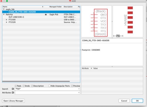
| FTDI header | 1 |
| 8pin header | 1 |
2.3 Eagle
-
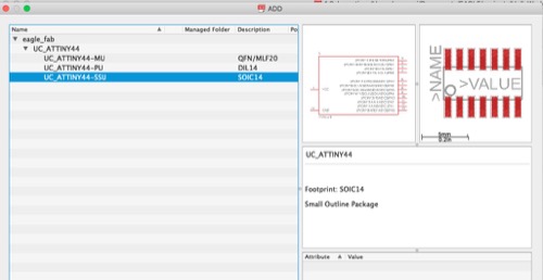
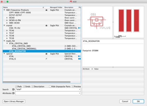
Install fab libraries
Download fab.lbr and open library manager to load fab parts libraries to my eagle library. -
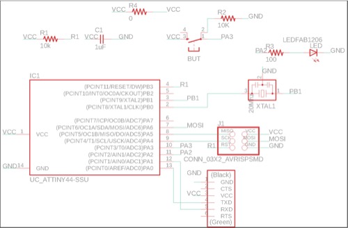
Create new project and schematic
-
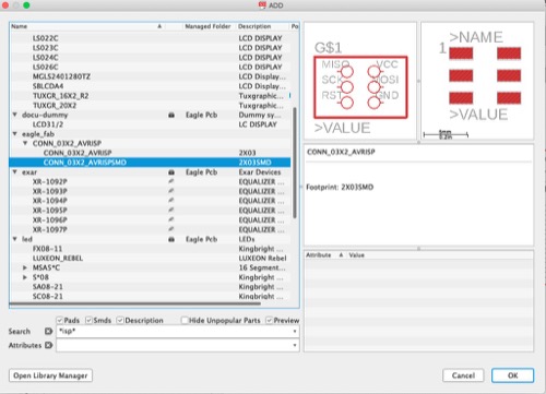
Add all the parts i need(including the LED as well as the button i will be using for the project) to the schematic and move them to the correct position
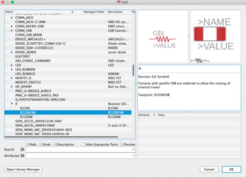
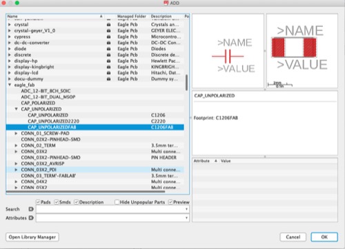
-
Make connections
First time i only assigned the value to make the the connection. Later on i redrew combined the 2.
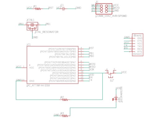
-
Export to .brd file for layout, adjusting the components’ position accordingly
-
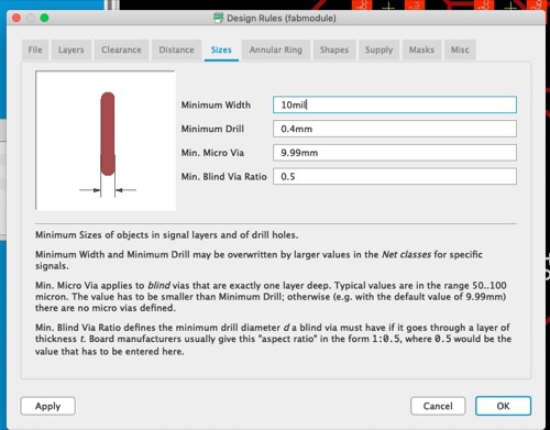
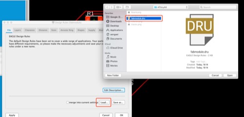
Download design rules and apply.
-
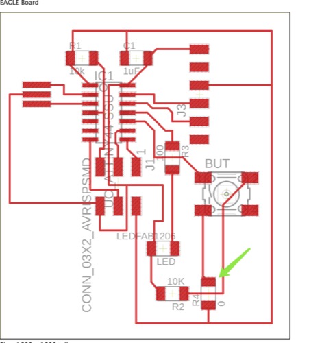
Tried both autoroute and manual route(When manual route it is very time consuming and it caused me more or less about 5 hours to finish). I finally went with my 2nd design to mill.
This was autoroute
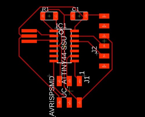
This was manual route. Notice that i added an 0ohm resistor in order the make button trace go to R2.
8.Design rules check - no errors. -
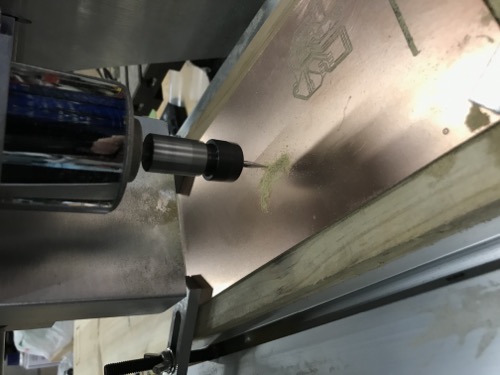
Milling
Export the .brd file to gerber files, and carried it to the CAM and then milling the board. I won’t cover too many details as details can be found in Electronic_Week_Assignment.
-
Stuffing
The progress is the same as the electronics production week. -
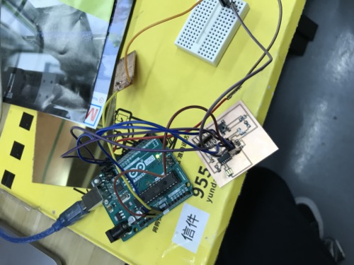
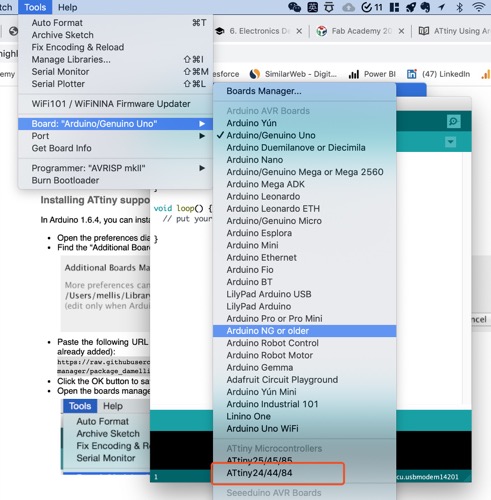
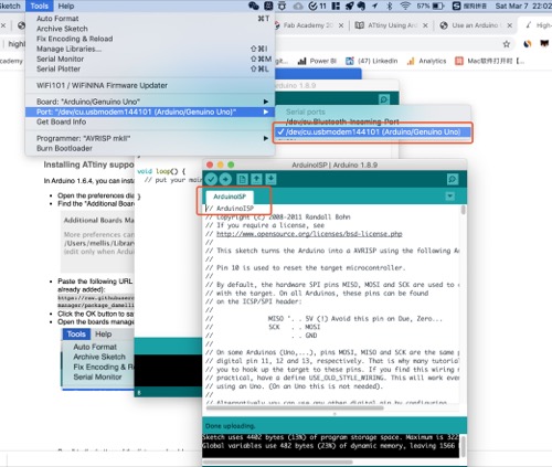
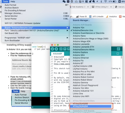
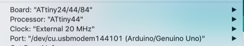
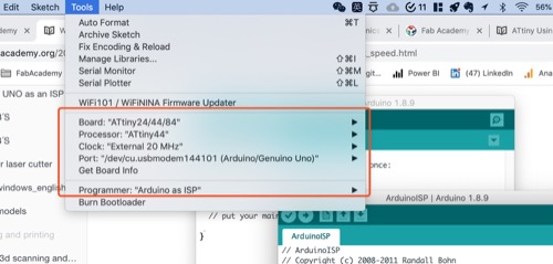
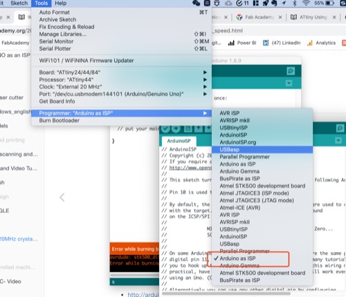
Testing
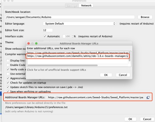
Instead of doing echoing ‘hello world’, i wrote codes to have my board controlling the LED through the Button. I used Arduino as ISP - Tutorials can be found here. I finally use Arduino to burn bootloader to my Attiny board so it acts like an Arduino now, just i would need to use the real Arduino to act as a forwarder to transfer the codes to my board.
- The codes i wrote as following -
int LEDPin = PA2;
int ButtonPin = PA3;


// the setup function runs once when you press reset or power the board
void setup() {
  // initialize digital pin LED_BUILTIN as an output.
  pinMode(PA2, OUTPUT);
  pinMode(PA3, INPUT);
}

// the loop function runs  a over and over again forever
void loop() {
  int ButtonStatus = digitalRead(ButtonPin);
  if (ButtonStatus == 1) {
    digitalWrite(LEDPin, HIGH);
  }
  else {
    digitalWrite(LEDPin, LOW);
  }
  delay (10);
}
3. Problems Occurred & Solutions
3.1 How to install libraries in Eagle and how to add fab.lbr?
Download fab.lbr and open library manager to load fab parts libraries to my eagle library.
3.2 what is the .echo file and the ino file that i downloaded used for?
They are the testing file written for testing if the board i made was useable. Will understand more of those codes in Embedded Programming week.