9. Embedded programming
1. Assignment && week workflow planning
1.1 Assignment requirements:
- Individual assignment:
Read the datasheet for the microcontroller you are programming
Program the board you have made to do something, with as many different programming languages and programming environments as possible.
- group assignment:
Compare the performance and development workflows for different microcontroller families
Document your work (in a group or individually)
2. How i did it
2.0 HeroShot of the week
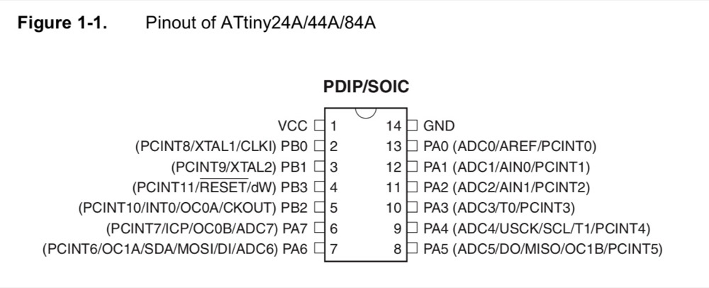
2.1 Attiny44 datasheet
ATtiny Pin 2 to Arduino Pin 13 (or SCK of another programmer)
ATtiny Pin 1 to Arduino Pin 12 (or MISO of another programmer)
ATtiny Pin 0 to Arduino Pin 11 (or MOSI of another programmer)
ATtiny Reset Pin to Arduino Pin 10 (or RESET of another programmer)
// slave reset: 10:               53
// MOSI:        11:               51
// MISO:        12:               50
// SCK:         13:               52
- Basic information
word:8-bit
2K/4K/8K Bytes Flash
128/256/512 Bytes of In-System Programmable EEPROM
128/256/512 Bytes of Internal SRAM
- From reading the datasheet of ATtiny44, i realized that when i wanted to use Arduino as ISP, the serial port connections i made was:
MOSI(ATtiny:PA6(PCINT6/OC1A/SDA/MOSI/DI/ADC6)->Arduino:pin11
MISO(ATtiny:PA5(ADC5/DO/MISO/OC1B/PCINT5))->Arduino:pin12
SCK(ATtiny:PA4 (ADC4/USCK/SCL/T1/PCINT4)->Arduino:pin13
reset(ATtiny:PB3 (PCINT11/RESET/dW)->Arduino:pin10
VCC->Arduino:VCC
GND->Arduino:GND
2.2 Program the Arduino Uno using Arduino IDE
// the setup routine runs once when you press reset:
void setup() {}

// the loop routine runs over and over again forever:
  void loop() {}
- Blink LED
Turns on an LED on for half a second, then off for half a second, repeatedly.
The circuit: LED connected from digital pin 12 to ground. A 560Ohm resistor connected.
 int ledPin =  12;

// The setup() method runs once, when the sketch starts

void setup()   {
  pinMode(ledPin, OUTPUT);
}


void loop()
{
  digitalWrite(ledPin, HIGH);
  delay(500);
  digitalWrite(ledPin, LOW);
  delay(500);
}
- Blink LED brightness level from 0 - 255, step 15. Use Arduino Pin9
int Brightlevel = 0;
int fadelevel = 15;
int ledpin = 9;

// the setup function runs once when you press reset or power the board
void setup() {
  // initialize digital pin LED_BUILTIN as an output.
  pinMode(ledpin, OUTPUT);
}

void loop() {
  analogWrite(ledpin, Brightlevel);
  Brightlevel = Brightlevel + fadelevel;
  if (Brightlevel == 0 || Brightlevel == 255){
    fadelevel = -fadelevel;
  }
  delay(100);
}
- Also some more with Arduino
2.3 Program my ATtiny44 with Arduino as ISP
-
The toolchain = Turn Arduino to ISP -> configure programme fuses by “burn bootloader” -> upload sketches to programme
-
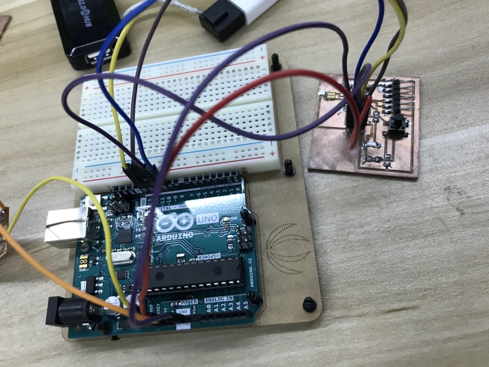
use Arduino Uno as my ISP so the first step is to upload the arduino_isp sketch to Arduino to make it an ISP and then wire the Arduino Uno with my board. This link tells you how you may use Arduino as an ISP.
-
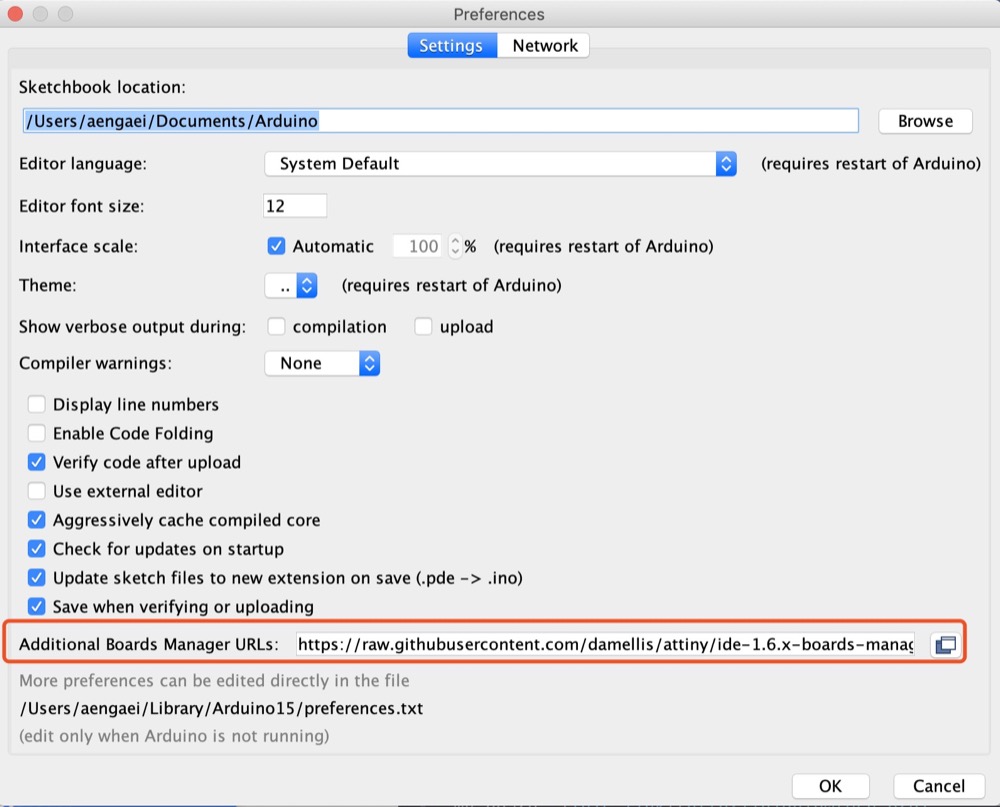
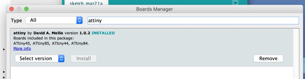
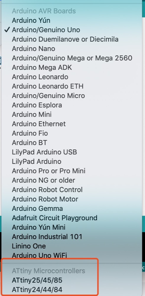
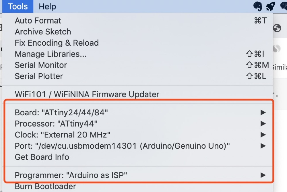
Configure the boards manager inside Arduino IDE.
onfigure the fuse bits of the ATtiny using ‘Burn Bootloader’ and the sketch are ready-to-be-uploaded.
- Button controlled ‘LED’ to be on and off, push the button and the LED will be on for 3 sec and turn off.
int led = PA2;
int button = PA3;

void setup() {
 // put your setup code here, to run once:
  pinMode(led, OUTPUT);
  pinMode(button, INPUT);
}

void loop() {
  // put your main code here, to run repeatedly:
  if (digitalRead(button) == HIGH) {
    digitalWrite(led, HIGH);
    delay(3000);
  }
  else {
    digitalWrite(led, LOW);
   // delay(5000);
  }
}
2.4 [Updated_1130]Other Embedded progam experience
-
I tried to read a DHT11 temperature sensor as well as an ultrasonic sensor from Input Device week
-
I tried to control a speaker during the output week
[Updated_0721]2.5 Comparison of ESP32CAM and ATTiny
-
I didn’t compare many microcontroller families as group assignment requested as i studied as an only student in my lab.
-
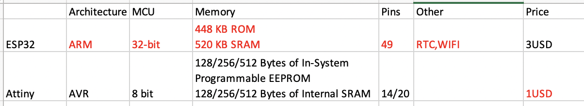
I later used ESP32CAM for my final project so i could summarize some difference and performances between ESP32CAM and ATTINY.
-
Like my final project, my board has to run a sever on the board it does require more memories, i should choose ESP32.
-
ESP32 and Attiny both can use Arduino as ISP to be programmed.
For this part i also put it on GroupPage
3. Problems Occurred & Solutions
3.1 Using Arduino as an ISP it requires a 10uF capacitor however i didn’t use but it still work. Why? What does the 10uF capacitor do?
It is connected between reset and ground.The capacitor prevents the Arduino board from resetting (which starts the bootloader), thus ensuring that the Arduino IDE talks to the ArduinoISP (not the bootloader) during the upload of sketches.
This has to do with the special way we will be using the arduino after we programmed it with the ArduinoISP sketch. Now we want to send code through it, not reprogram it. If we leave out the capacitor the arduino will interpret us sending code to it as an attempting to reprogram it and do an automatic reset, sending the code that we inteded for our FabISP to the arduino bootloader instead. If we include the capacitor, it absorbs the reset pulse and lets us send the code through the arduino to the FabISP card being programmed instead.source
When avrdude connects to the serial port the DTR signal is asserted, which has the side effect of triggering an auto reset. So avrdude then finds itself talking to the bootloader rather than the ISP sketch. The capacitor absorbs the auto-reset pulse and allows avrdude to establish proper communication with ArduinoISP.
- I guess the reason it worked without the capacitor was that i kept the Arduino running after the ISP sketch loaded. However if i restarted it would reset and bootloader would be running thus it would not be in ISP mode again. I would like take an experiment to verify whether my assumption was correct or not.