8. Computer controlled machining
1. Assignment && week workflow planning
1.1 Assignment requirements:
- Group
test runout, alignment, speeds, feeds, and toolpaths for your machine
- Individual
make (design+mill+assemble) something big
1.2 Preparation
My final project is to build an automatically IoT dog feeding project. This week for building something big, i’m thinking of building a dog house, where i can put my final project in the house as part of the whole project. I searched out some docs and examples online in order to give me some thoughts on what i should build, what structure my project should be looking like, as well as the joints, combining options out there.
I’m thinking of having the house several functions:
- For dog to have food, walk around and their bedroom as well
- The roof can be a sofa for human, my dogs are sleeping while i’m reading or resting above them.
- The front door can be opened so it makes it easier for moving stuff, replenishing food as well as cleaning.
2. How i did it
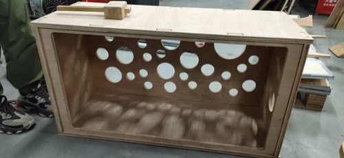
2.0 HeroShot of the week
2.1 Fusion 360
-
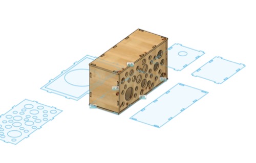
The dimension of the house will be 1000mm(Length) * 400mm(width) * 500mm(Height),and the Material thickness that i use is 16.8mm.
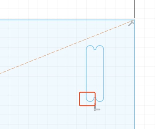
-
As the diameter of the drill i will be using is 8mm, so i have to make 8mm dog bones.
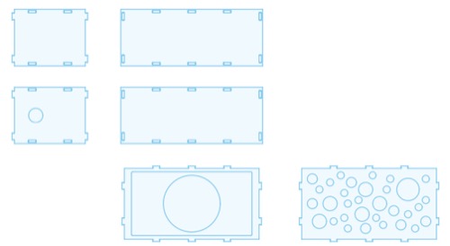
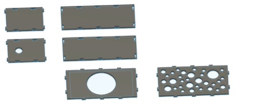
-
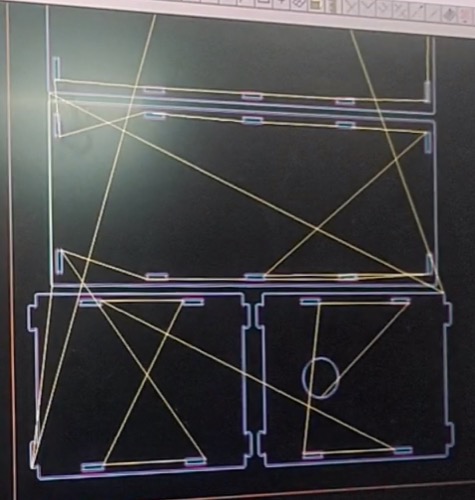
Then i draw the design made of 6 pieces of boards, tried to assemble it and render it. For details how to process with Fusion360 you can find from my previous assignment in Week03
-
Save as .DXF and carried it to the CAM tool.
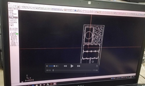
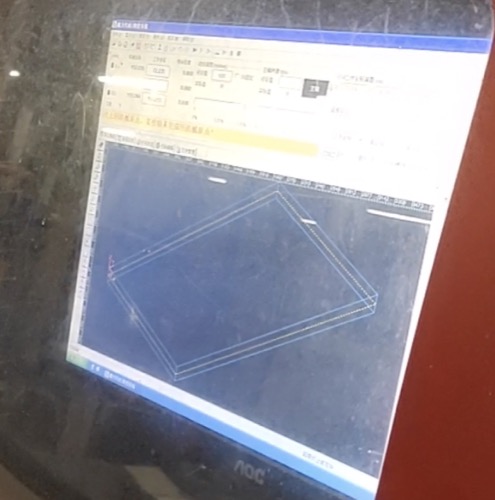
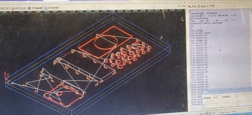
2.2 CAM (This is extremely time consuming setting the tooth paths)
- The CAM software i use is Mill9.1
-
The cutting logic should be cutting the inner parts first and then the outer - Otherwise if cutting the outer parts first then it will be not easy to make the board stable to cut the inner parts.
-
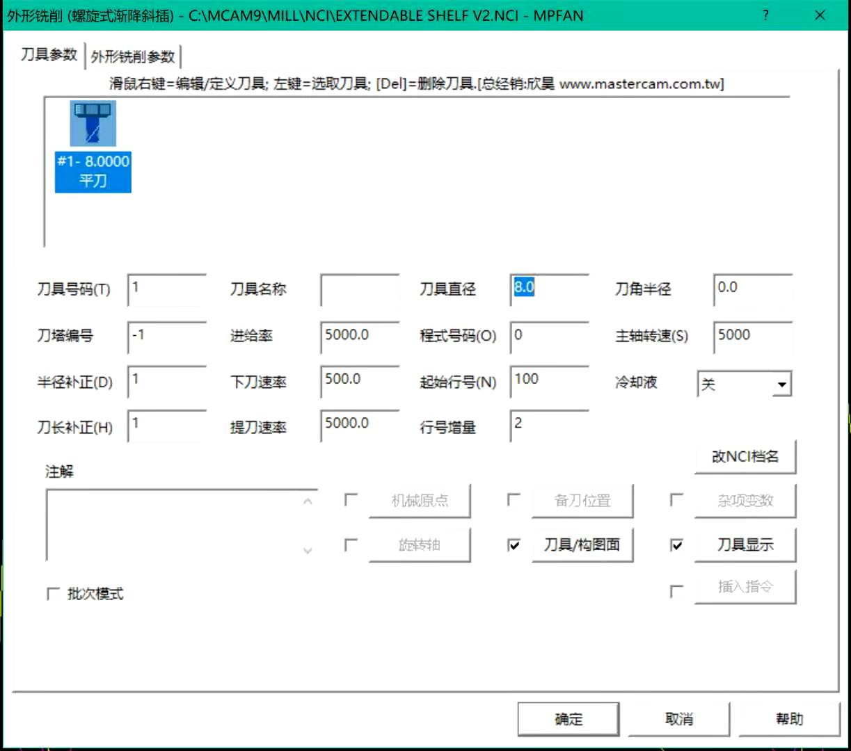
Select the tool - i use the 8mm flat end mill.
- feed rate(my speed) choose 500:refers to the distance/sec that mill cut down into the object
- surface rate(my feed) 5000: refers to the speed that the mill goes according to the set up toolpath.
- Cutting depth -17.1(As the thickness of the material i use is 16.8mm)
I looked up a little bit more searching on CNC terms and i figured that i mistook translating the term. This link specifically refers to the,Feet per Minute (SFM).
“my speed” = plunge feed = feed rate “my feed” = plunge rate = surface speed
In order to avoid misunderstandings. I changed my version of “speed” to “feed”, my version of “feed” to “surface speed” in my documentation.
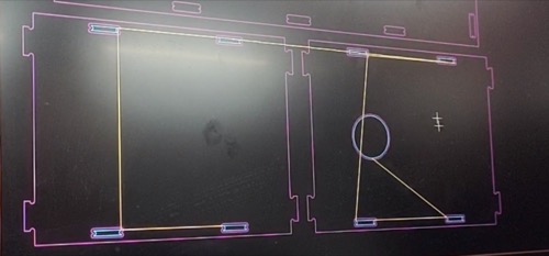
- Routing the toothpaths
- save and generate Gcode after routing the toothpaths and carried it to the machine.
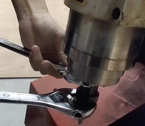
2.3 Machining
First thing to do is to set up the machine in the software attach to the machine.
Change the end mill
Adding fixture to make it stable, i used in total 6 fixtures to make it stable.
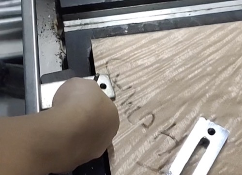
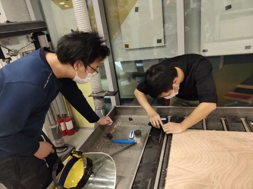
Adjusting the mill to “touch” the board and make it the “zero” point.
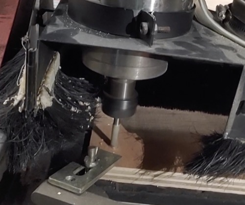
The toothpaths in gcode seems to work well
And, here we go!
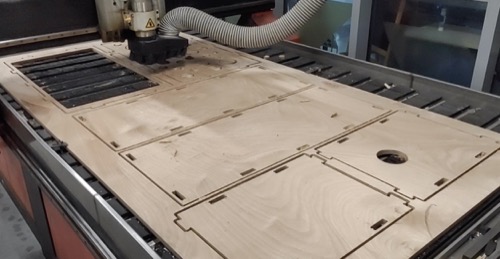
Turn the fan on and start cutting

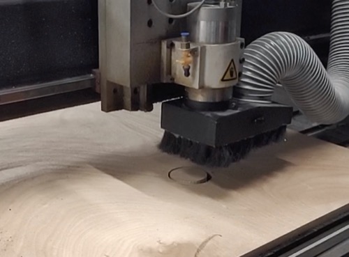
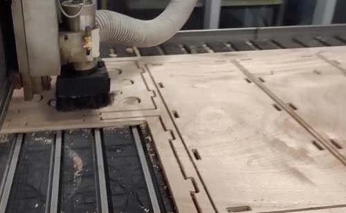
After 1 hourish cutting it’s done.
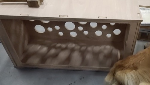
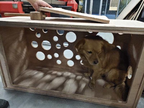
2.4 Assembling
Well fit! I’m not going to put the door on yet, as the following weeks i will need to put it the IoT hardware and other parts in it, i will leave it like this for now.
3. Problems Occurred & Solutions
- In the CAM tool when i was doing the routing i couldn’t make sure how the toothpaths will go according to my designs.
I asked my tutor and also the lab manager who is experienced with the CAM tool - Mill9.1 - does have this tricky problem. Would need to try several times to make sure the toothpaths would be the way you designed.