14.Networking and Communications
1. Assignment && week workflow planning
1.1 Assignment requirements:
- individual
Design, build, and connect wired or wireless node(s) with network or bus addresses
- Group
Send a message between two projects
1.2 Preparation
- Read previous students work and learn what they did previously
Use Serial communication to have 2 projects talk to each other
Use I2C to finish the assignment
Use 2 bluetooth modules, connect to 2 projects and have them talk to each other.
-
Read Tutorials from Fabacademy
1.3 My workflow of the week
-
Group_Assignment—Through Serial Communication to have 2 boards talk to each other, referring to Lakaz_Assignment
-
Individual_Assignmnet—Use ESP32 CAM with board module to create a board, develop a web interface and through it, shows the esp32 CAM real time video, as well as datas or even control back to ESP32 board.
2. How i did it
2.0 HeroShot
2.1 Group assignment
I used 2 Arduinos(One Seeeduino - an Arduino compatible and an Arduino Uno).
I used the UART serial communication, to have Arduino to control the on-board LED on on the Seeeduino.
Codes on Seeeduino as following -
void setup() {
  // put your setup code here, to run once:
  Serial.begin(9600);
  pinMode(13, OUTPUT);
}

void loop() {
  // put your main code here, to run repeatedly:
  if (Serial.read() == '1') {
    digitalWrite(13, HIGH);
    delay(2000);
    Serial.println("hello");
  }
  else
    digitalWrite(13, LOW);
}
Codes on Arduino as following -
void setup() {
  // put your setup code here, to run once:
Serial.begin(9600);
}

void loop() {
  // put your main code here, to run repeatedly:
  Serial.print('1');
  delay(2000);
}
Use an wire connects from Tx on Arduino to Rx on Seeeduino.
2.2 Individual Assignment
2.2.1 Create a new board with ESP32 CAM module
First of all to design the board with EAGLE. First problem i met with is that ESP32-CAM where i can find the part in EAGLE? Like following layout from Neil’s
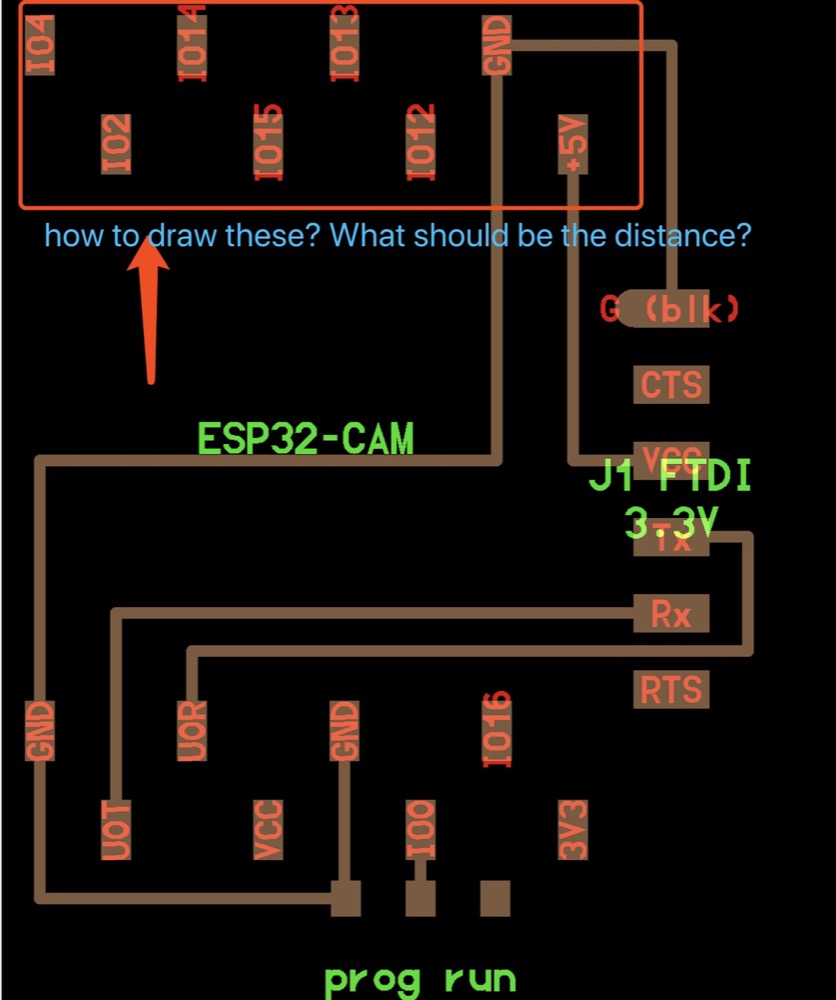
YuFei told me i would need to design the parts by myself.
Design the parts:
- Eagle->library manager->edit
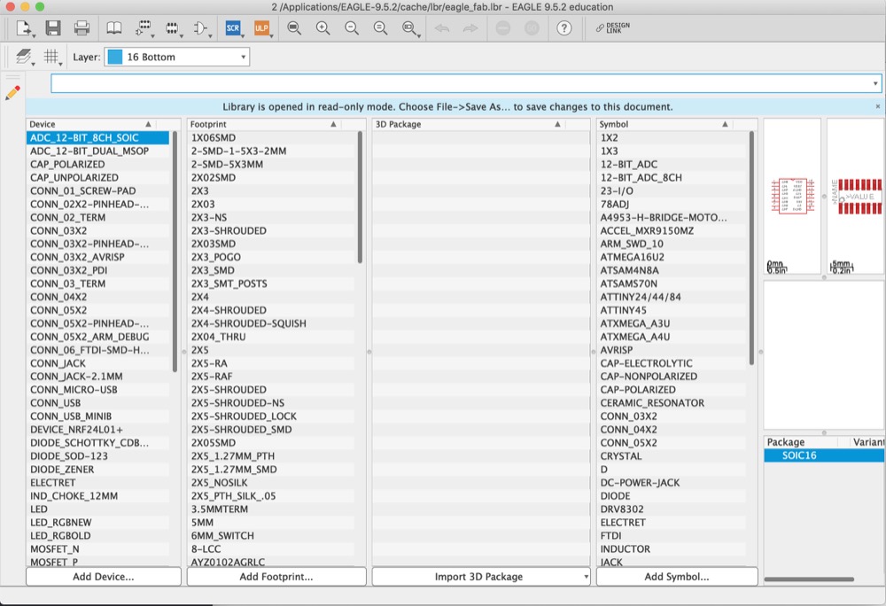
-
Layout redesign: Duplicate and modify “1X06SMD” from “footprint” and make it from 6 pin to 8 pin, save as “1X08SMD” and library named “eaglefab_ESP32”
-
Schematic redesign: Duplicate and modify “PINH2X5” from “symbol” and make it from 5 pin to 8 pin, 2 column to 1 column. save as “PINH1X8” and library named “eaglefab_ESP32”
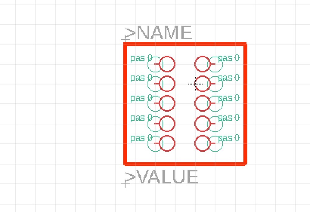
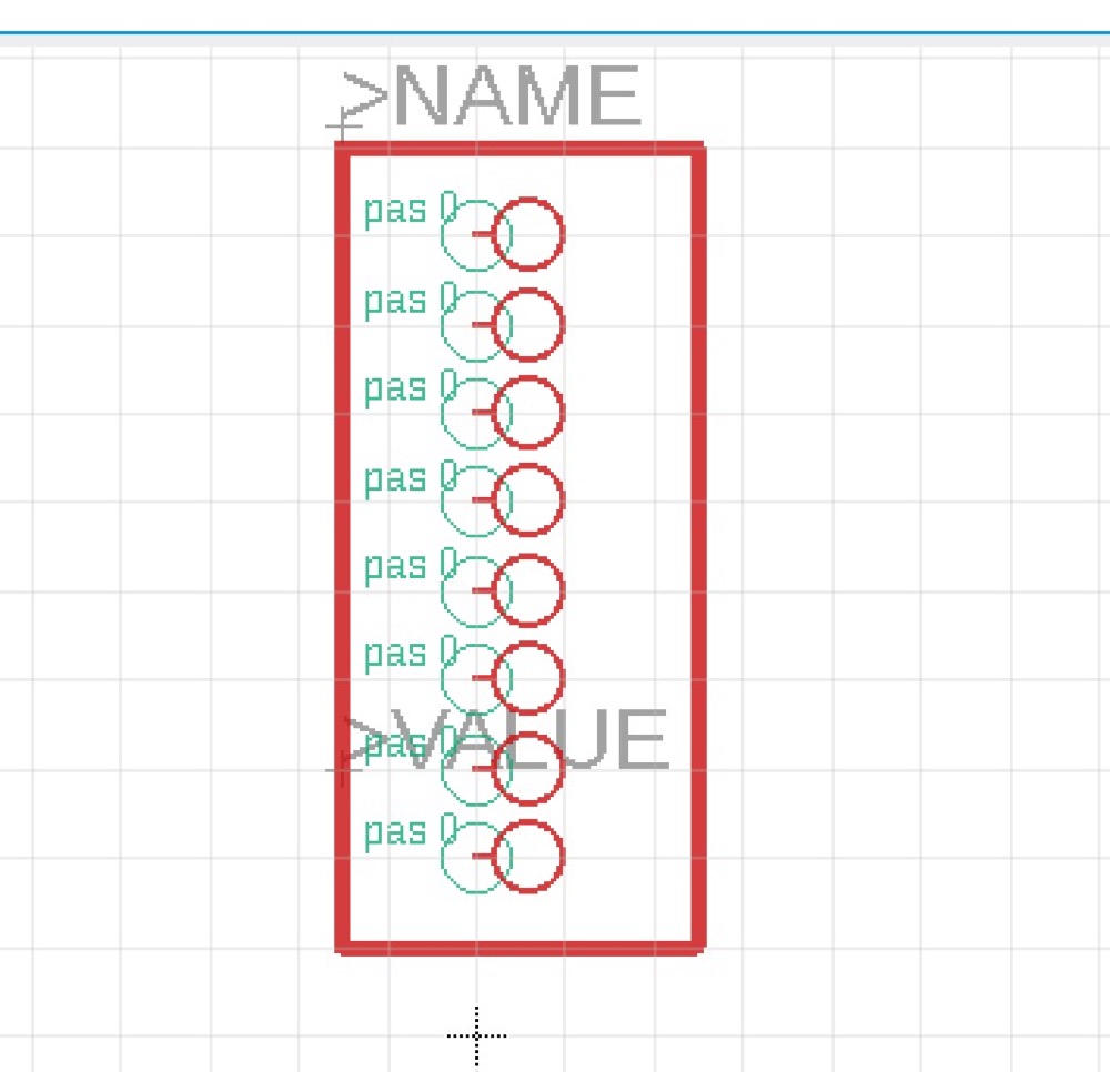
-
Add a new device, name it “CON_ESP32_CAM”. Add my symbol “PINH2X5” and click “new” to add my footprint “1X08SMD”. Connect each pin together and then done.
-
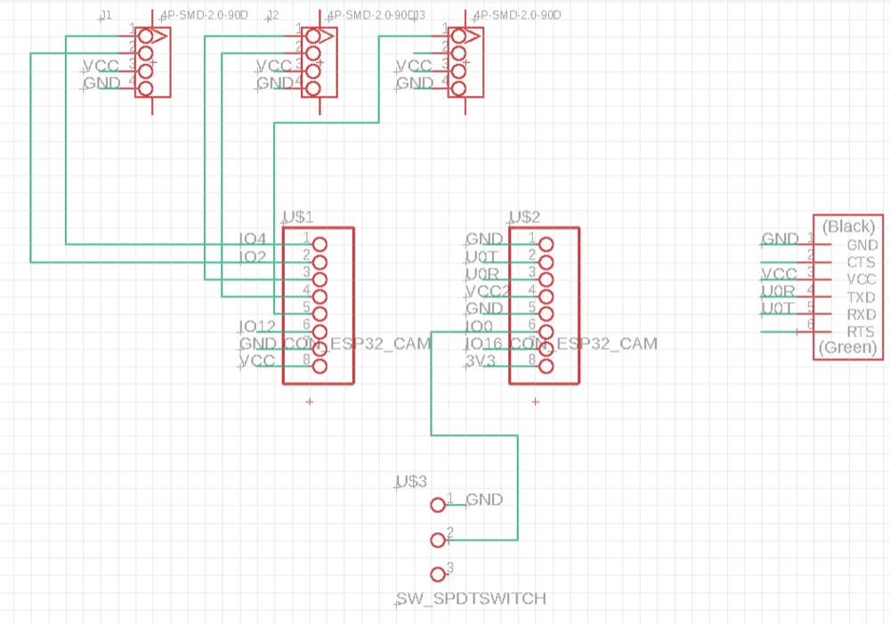
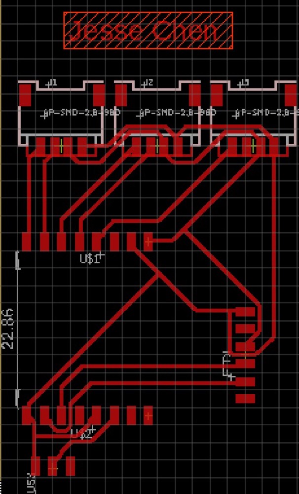
My Schematic && layout
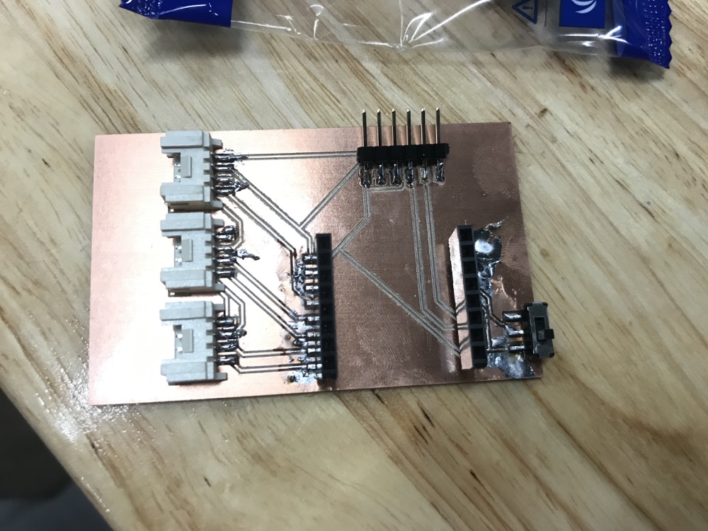
- Have it milled and stuffed and finally looks like this
2.2.2 Talk to ESP32 webserver through my laptop, Show the esp32 CAM real time video
I use the in-site search from FabAcademy and put “esp32-cam” in and a very helpful work done by another student was helpful. There was some takeaways according to his work:
-
Need to add ESP32 to Arduino IDE if i want to use Arduino IDE.
-
It might need a FTDI programmer for programming the ESP32-CAM. Is it true? And why?
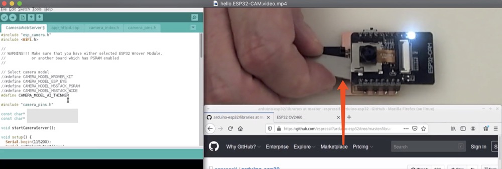
I found a quick starter guide for getting the ESP32-CAM working - ESP32_CAM_QUICK_SETUP.
Wire up the ESP32 to do a quick setup and test run.
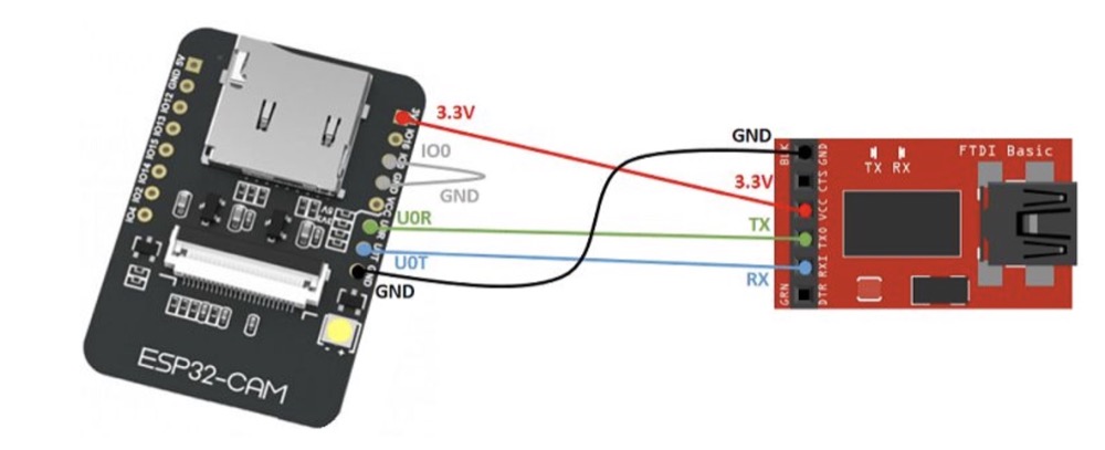
Take above pin connection reference i wired up my board
I’m using Arduino IDE to program the board. First step is to Install_ESP32_ON_ARDUINOIDE.It’s quite simple just 2 steps:
1)Copy and paste “https://dl.espressif.com/dl/package_esp32_index.json” to Arduino->preference->Additional boards… -> OK
2)Tools->Board manager->search ‘esp32’ ->install
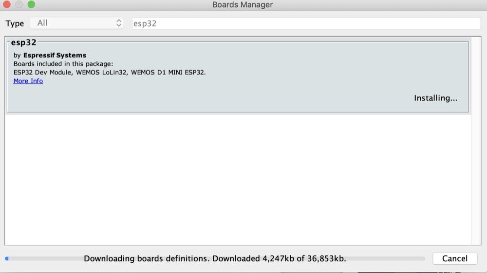
Arduino IDE set up.
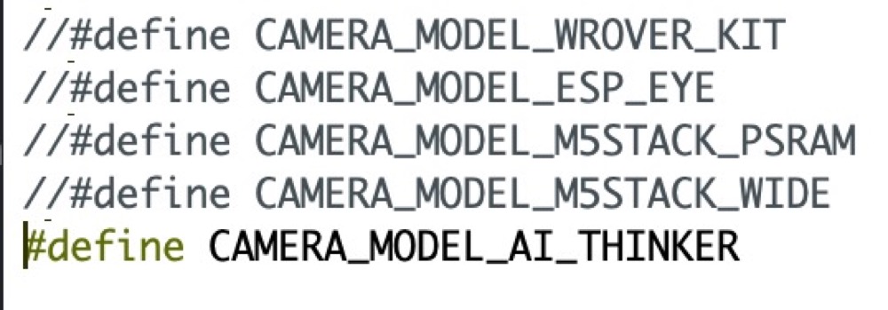
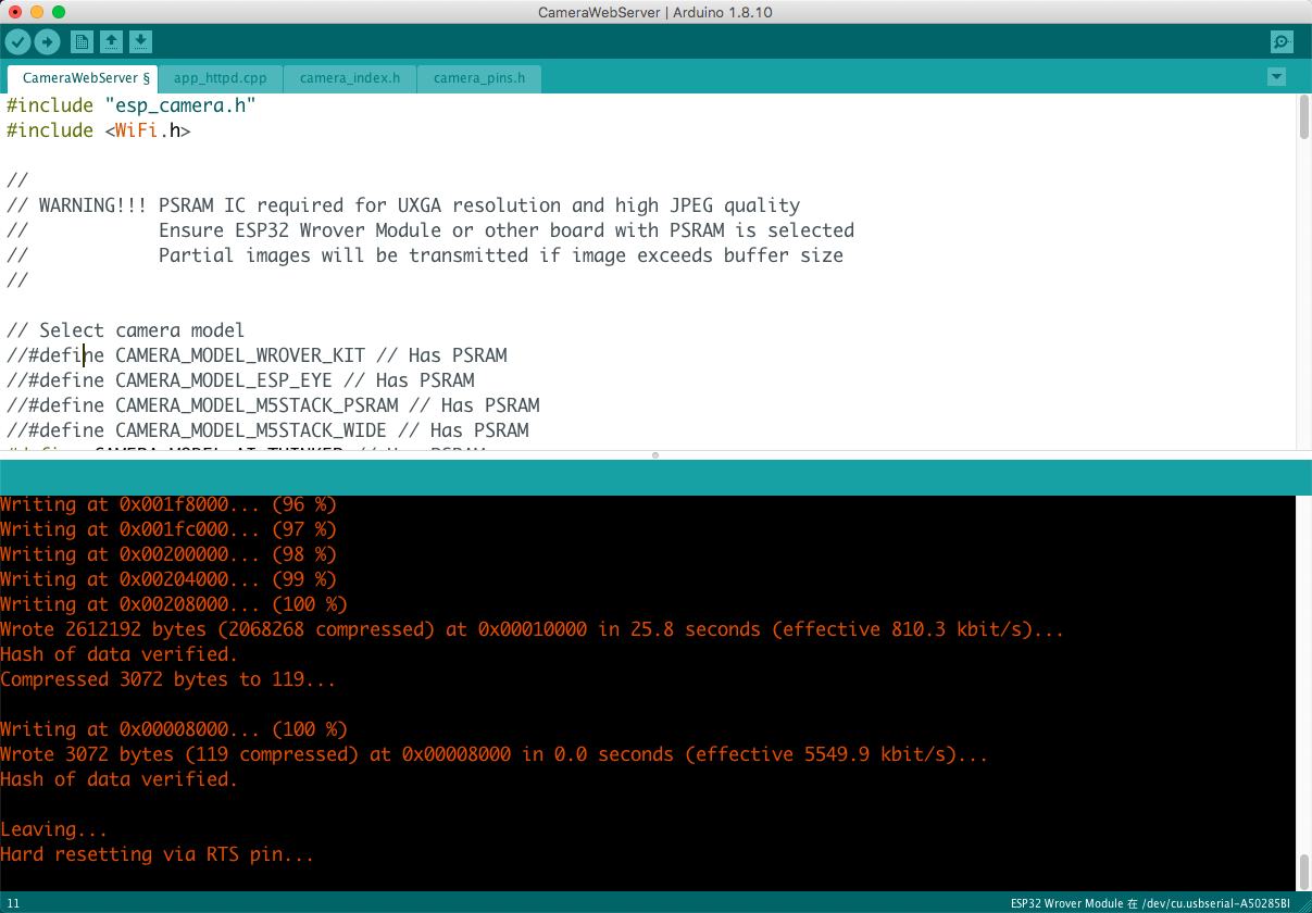
Import the example code ‘cam webserver’
Comment out the default #define and make AI_THINKER available.
Fill in the WIFI user name and password.
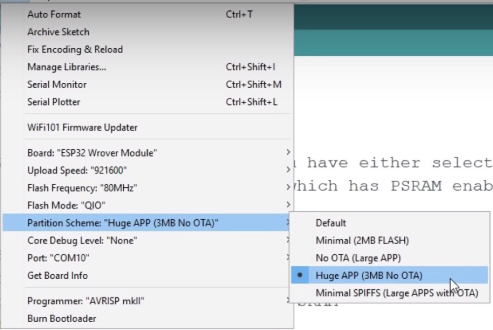
Compile and upload the codes.
- After code loaded unconnect the wire from GND to IO0(On my board switch the button) and press reset
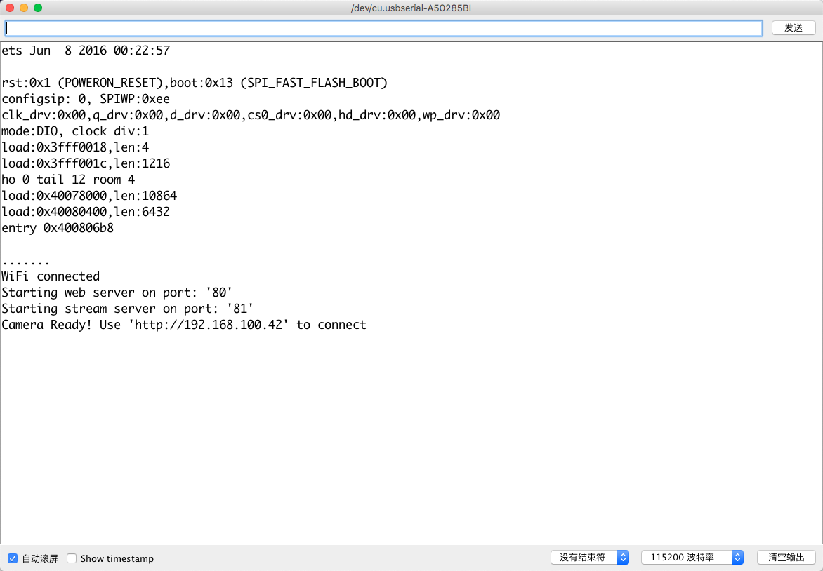
- HeroShot
[Updated 201231]2.3.4 Part of my final project
-
ESP32CAM module that i used this week become the main controller of my final project.
-
In my final project i modified the ESP32 web interface in HTML, to add a button ‘Give Food’ referece to 2.4.1 section of my Final Project
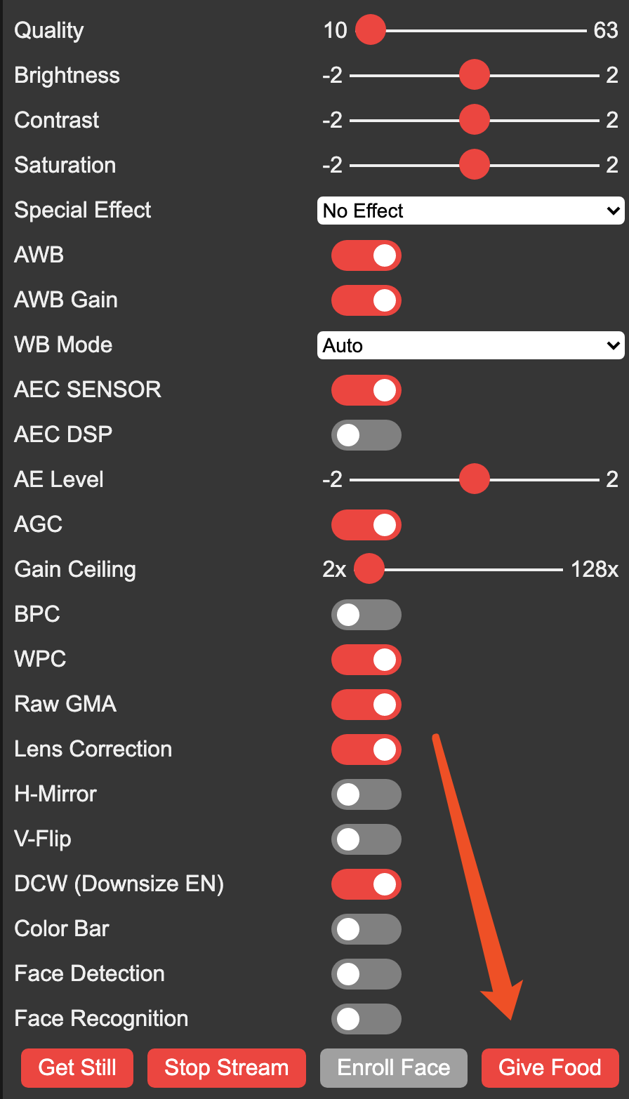
- Then i made my ESP32 board servo to be controlled by the button, an IoT function that using network to have mobile device talk to the board. Reference to 2.4.2 section of my Final Project
3. Problems Occurred & Solutions
3.1 ESP32-CAM where i can find the part in EAGLE?
Design by myself
3.2 Do i need a FTDI programmer for programming the ESP32-CAM?
Yes.
3.3 How to make SPI interface with ESP32?
3.4 What was Neil doing putting a metal underneath the board before uploading the codes?