3. Computer Aided design
1.Assignment && week workflow planning
1.1 Assignment requirements:
-
individual
-
model (raster, vector, 2D, 3D, render, animate, simulate, …) a possible final project, compress your images and videos, and post it on your class page
2.How i did it
My final project as i described previously in my first assignment - I would like to build an interactive dog feeding machine with automatic functions as well. For the automatic function i expected it to be like this: in certain points of time in a day, the machine will drop puppy food to the bowl automatically.
In this case, the structure of my project, it should have room for storaging the food, a “button” that OPEN|OFF automatically in a day which would trigger some automation that food will drop to the bowl from the storage.
Below was what i did in a week.
2.0 HeroShot of the week
- 2D vector(InkScape and Fusion360)

- 3D(Fusion and FreeCAD)
2.1 InkScape
-
I plan to use it with as logo design for further cutting on a vinylcutter - A logo for company sticker.
-
First i copy and paste the Seeed company logo into InkScape

- Then i create another layer and and draw the skeleton with Bezier pen, modified then to make my drawings to cover the company logo pasted earlier in the first layer.
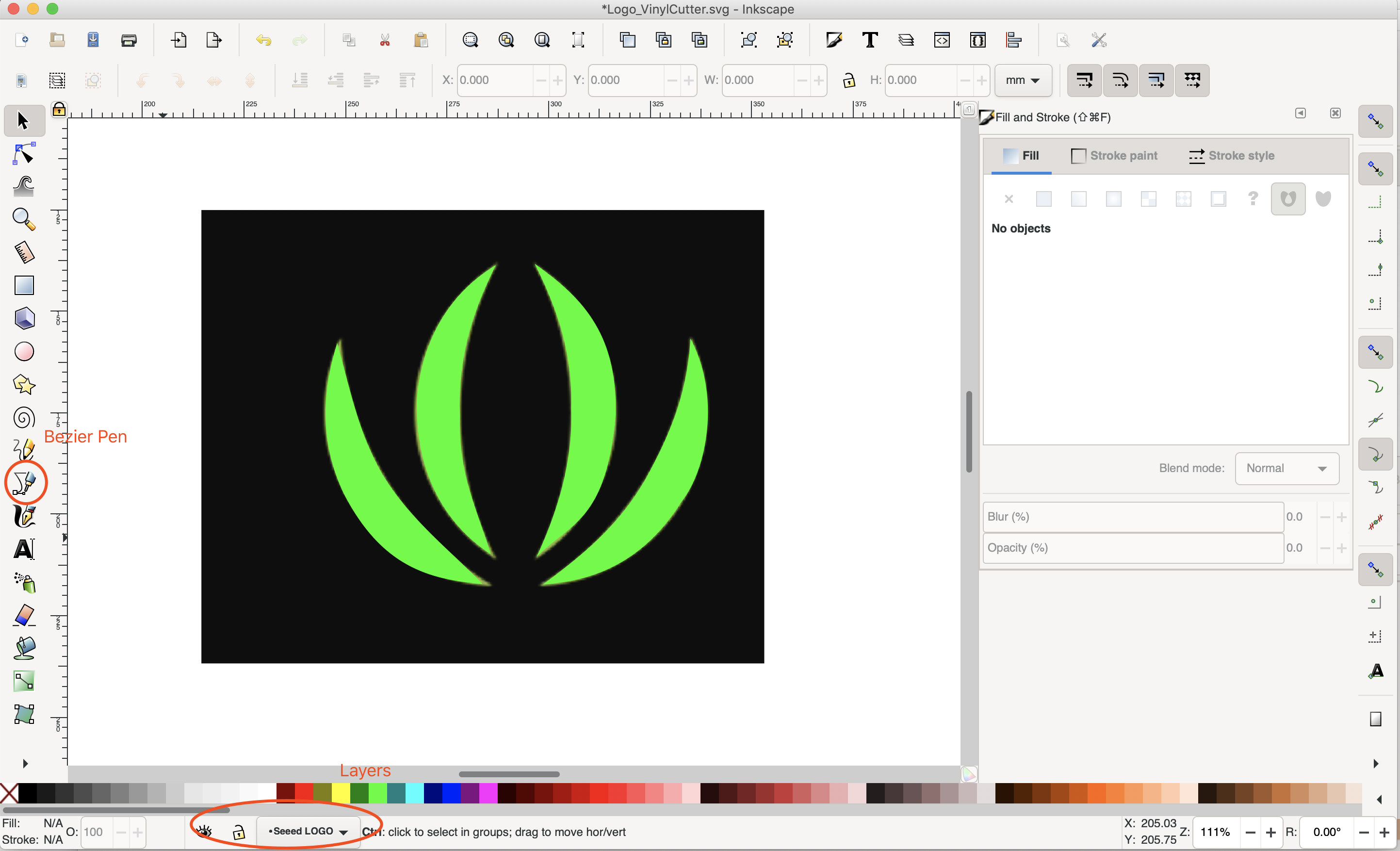
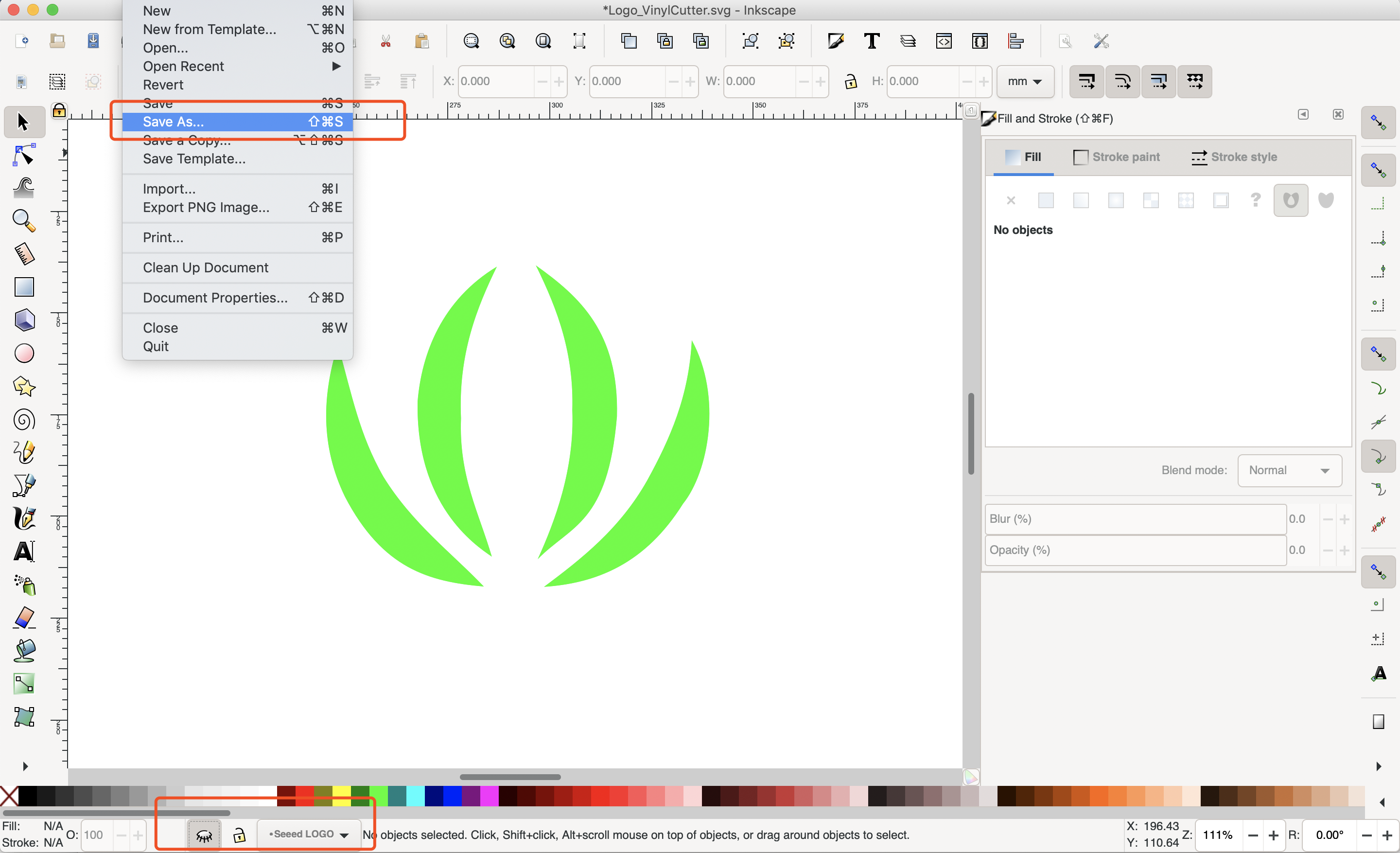
- Hide the first layer and save the file, done.
2.2 Fusion360(2D and 3D)
Downloaded Fusion 360 and plan to use it with 2D design for further cutting on a Laser Cutter
I decided to go with Fusion 360 First to make a simple case.
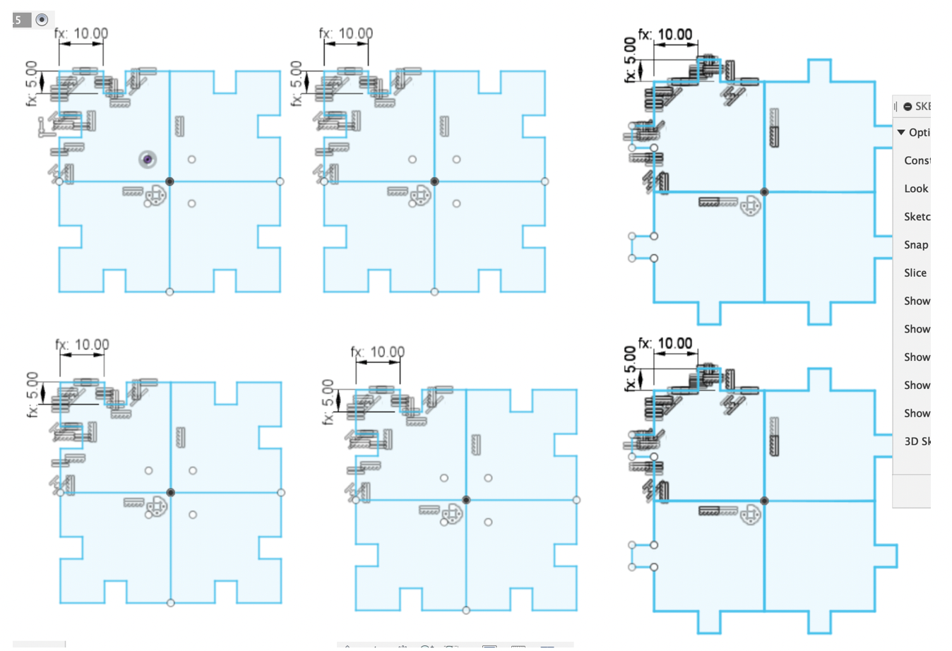
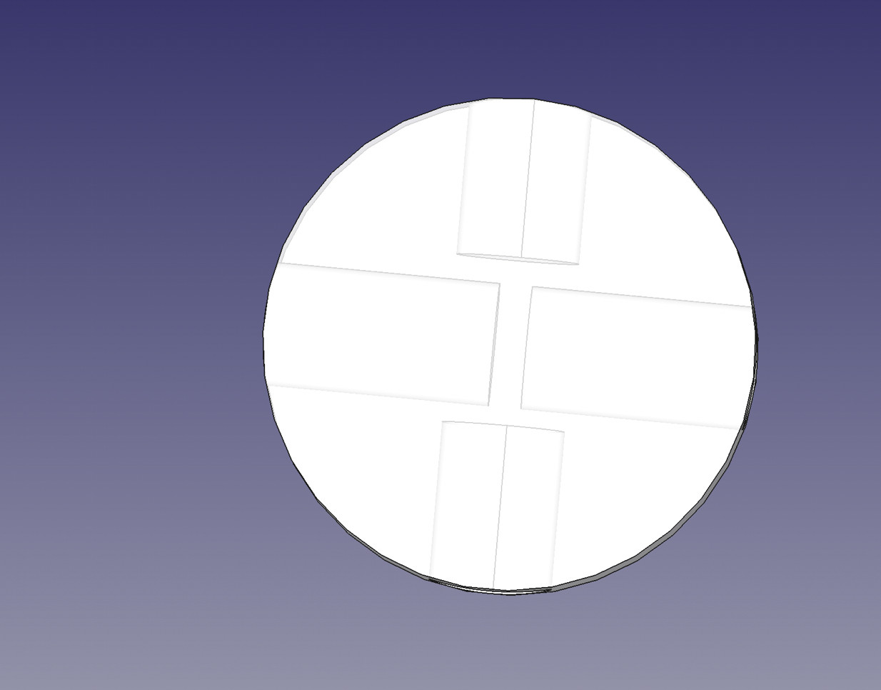
In order to make this case i’m supposed to have 2D design for the 6 parts and then entrude them to 3D, determine those parameters(So called a parametric design).
- I made my initial sketch(1/4 of a squre), Using “Circular Pattern” to make kit a big part, and then copy and paste to 4 exactly same part. The other 2 did the likewise. I set the parameters and constraints, making sure i can easily adjust the numbers according to the materials later i will be using from the lab.
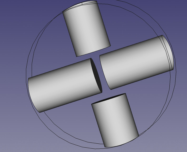
- Extrude the sketch and make it 3D, in order to prepare for assembly testing and Animation.
- Assembling before using machine
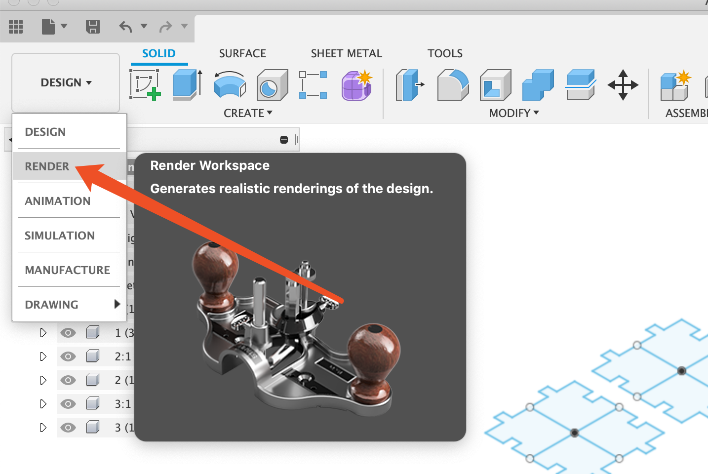
- [Updated_0717]Render with Fusion360
Render option and it goes to “pre-rendering mode”
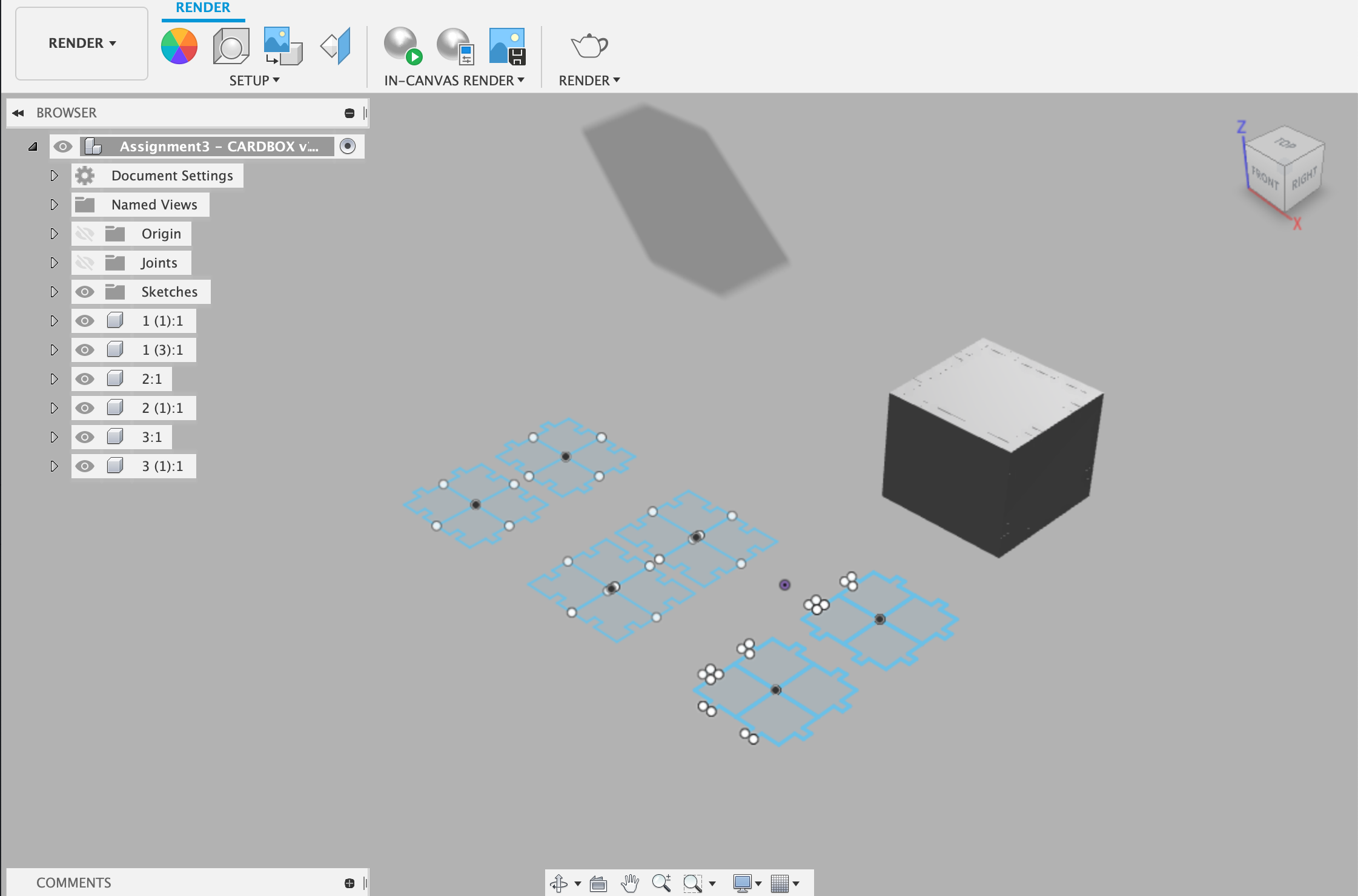
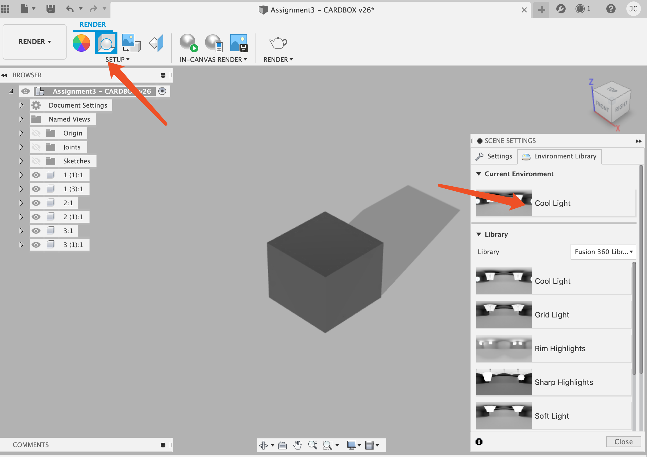
Change the environment to “cool light”
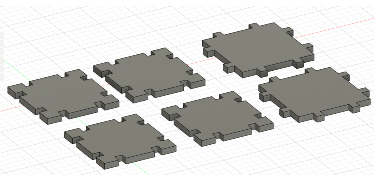
Render the box with random seletions as showing below
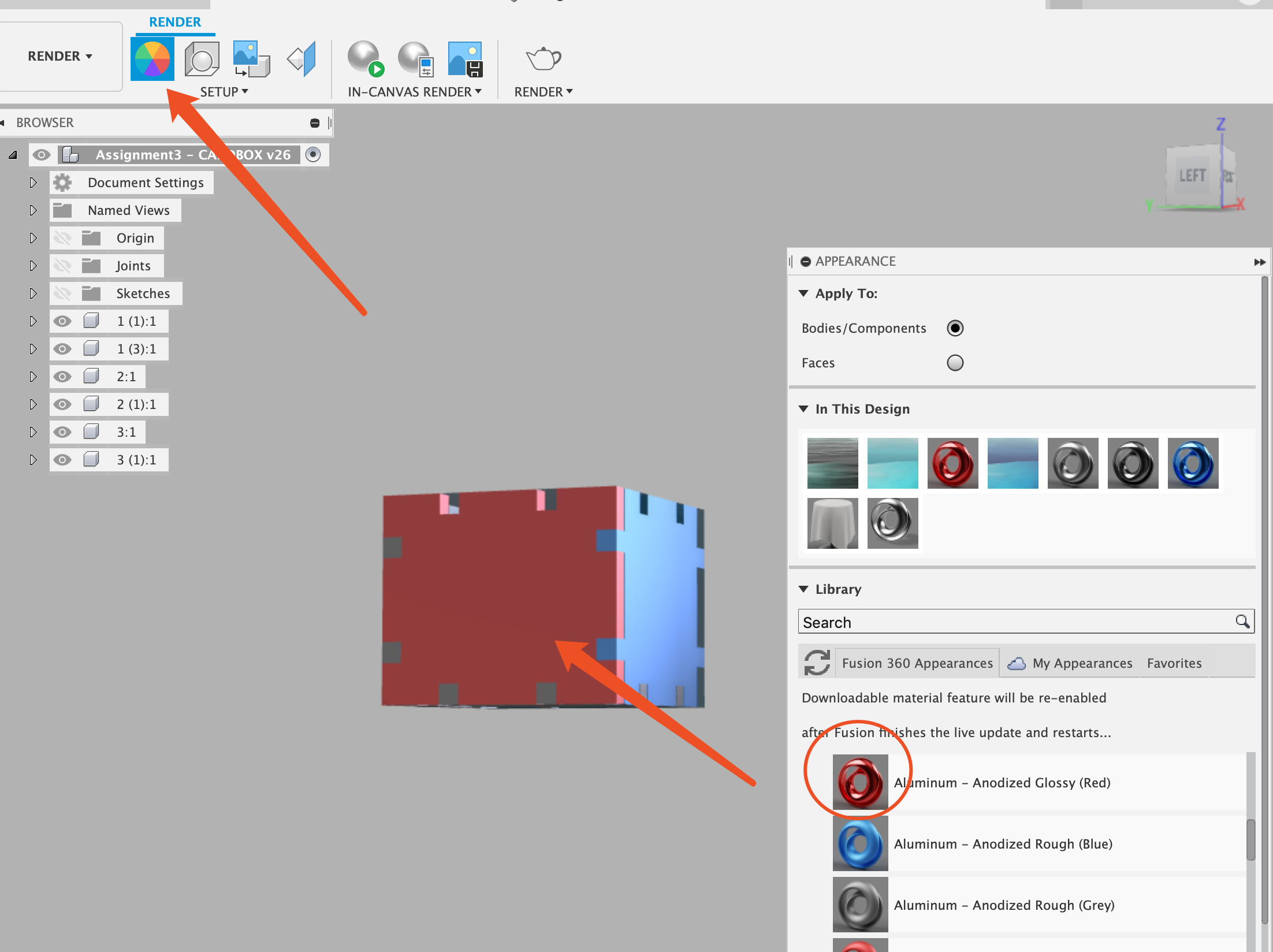
It does not look like anything but i am just trying to explorer what render looks like and how i can use it.
2.3 FreeCAD(3D)
-
I downloaded and Install freeCAD
-
Tried with the Part design
-
Tried Offset
-
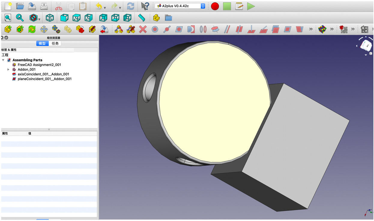
Assembly
-
Rendering go to Raytracing workbench, select RadioCitynormal. However i was not able to render. I will describe my problem in the next title.
-
recording my screen I was using the quicktime player that comes with Mac to record my screen
-
compressing my video files using ffmpeg I downloaded ffmpeg, the download progress is not easy. I found this very helpful youtube tutorial on this,It will be very helpful if you are using Mac as i do.
-
After having my video files and ffmpeg installed, i go to my video directory and then i use following command for compressing my screen record.
ffmpeg -i input.mp4 -c:v libx264 -crf 24 -preset slow output.mp4
Below is before and after the video file compressed.


- Featuring my video to my class page
3.Summary of the tools that i used this week[UPDATED_0716]
-
InkScape is a good tool for make 2D drawing works but it is not doing good in terms of the parametric design.
-
For parametric design of 2D works and 3D design, Fusion360 works pretty well.
-
Comparing Fusion360 and FreeCAD i will go with Fusion360 in the future. There are several advantages that i like with Fusion:
1)It is more popular, has much more online tutorials and materials that i can learn from, will decrease my barrier obtaining the skills of designing
2)It is an online tool that doesn’t require too much of a very strong computer hardware to run it. So in the future even run with my older desktop, it will work pretty fine.
3)FreeCAD’s functionalities
Problems Occurred & Solutions
- which software i should use for finishing my project? I went ahead with FreeCAD, as i was told it was the software that able to do all from 2D,3D and all the way to render and animation or simulation.
- For video compress and upload, which tools(I will need to learn)? FFMpeg is the tool for me.
- How i can check the inside - I found a solution that i can change the transparency degree to 50 or more so i will be able to see inside it
 - assembly
How do i make sure it is 90 degree?
- assembly
How do i make sure it is 90 degree?
 Cannot assemble them the two together
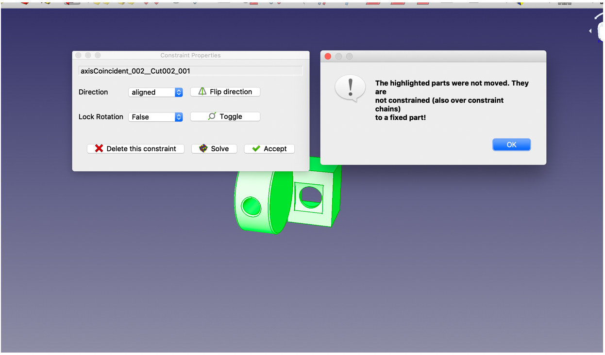 I searched on line and a found a discussion here
The way you are using A2plus is not correct. The parts have to be imported from external files to the assembly. If doing so, each A2p object has the property “fixed Position” in the property editor of the combo view.
So in order to solve this probelm i will just create a new file, go to A2plus workbench, and then import the 2 parts files i did earlier. And now it worked.
- When i was tring to render my project There’s a problem poped up as following
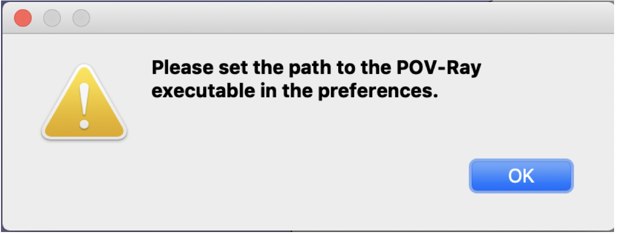 I followed some tutorials and looked up some documentation. It seems like i will need to download POV-Ray and have some settings. However internet access was way too bad to get access to that. I will have this of my questions solved later.
[Updated_0717] I used Fusion360 to try render, you can find it in this document above where i was describing the rendering.