4. Computer controlled cutting
For this week, we have a group work. So we have to clone agrilab git.
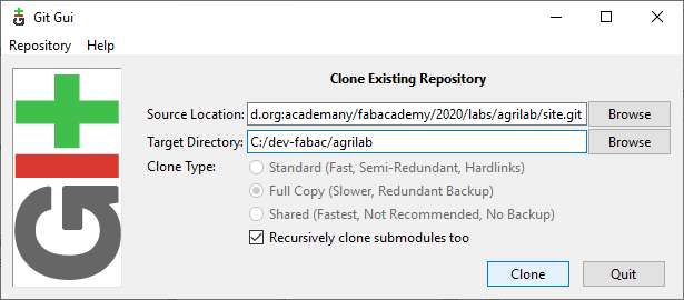
but, Olivier and me can’t push to master. So we will work on this point during next week…
edit: I can only create and push to branches. Instructor have to merge branches to master.
Vinyl cutter
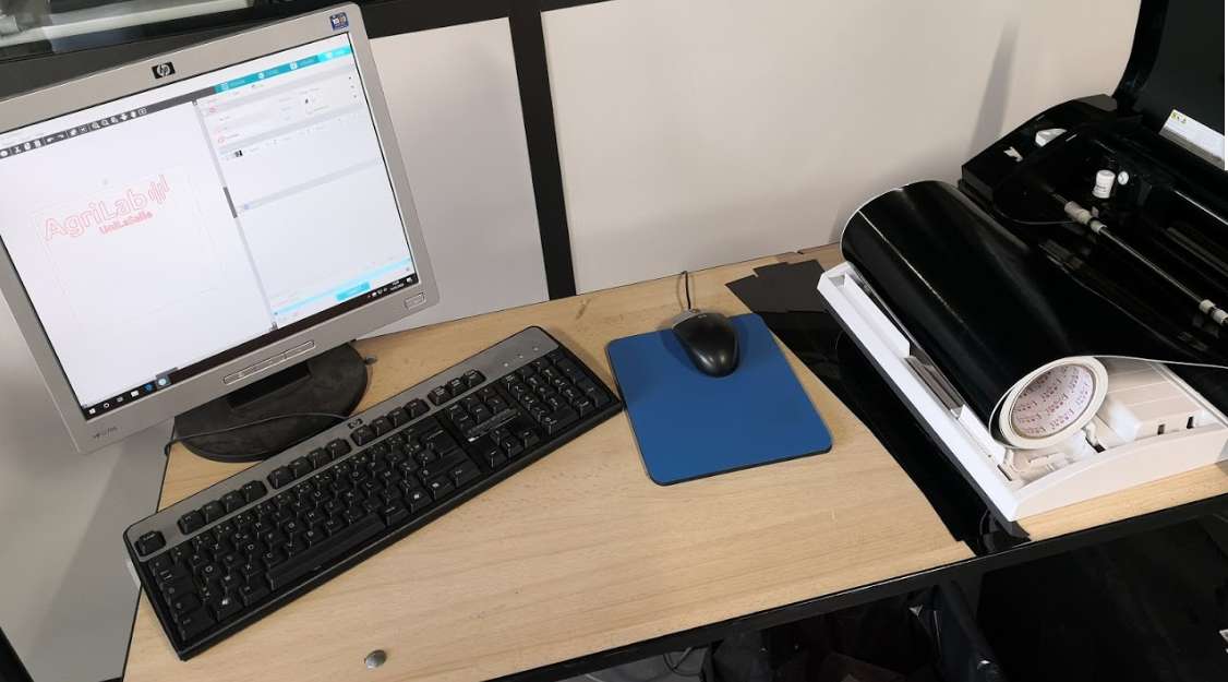
For this exercises, I will use a Silhouette Cameo 3 (now it’s the v4). It works with the software Silhouette Studio.
Max Cutting Area 12 in. x 12 in. (mat) 12 in x 10 ft. (roll)
Max Media Thickness 2 mm
You can use pens or blades to draw or cut materials.
Heat Transfer vinyl
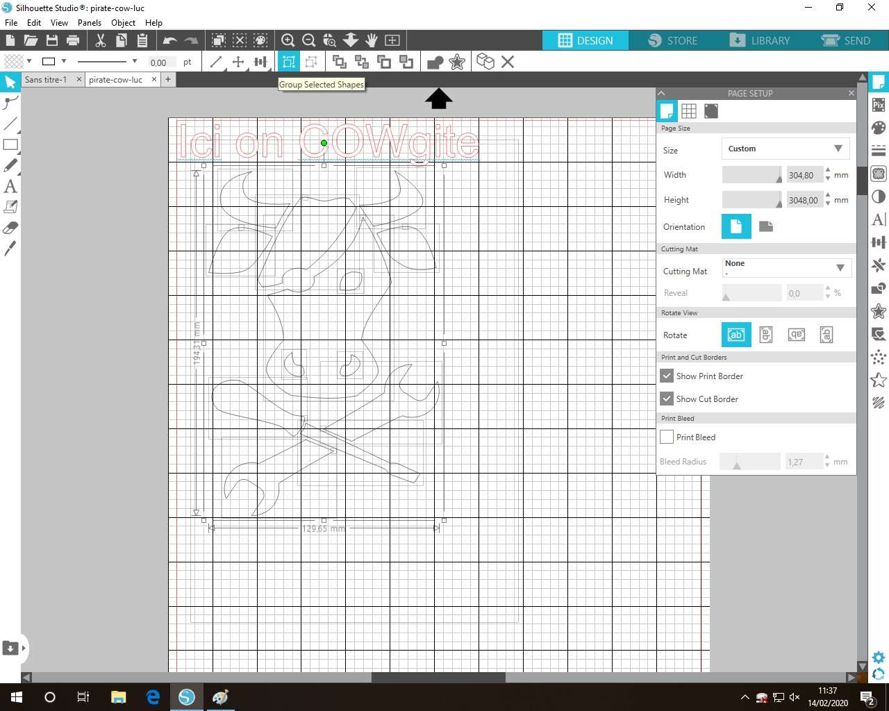
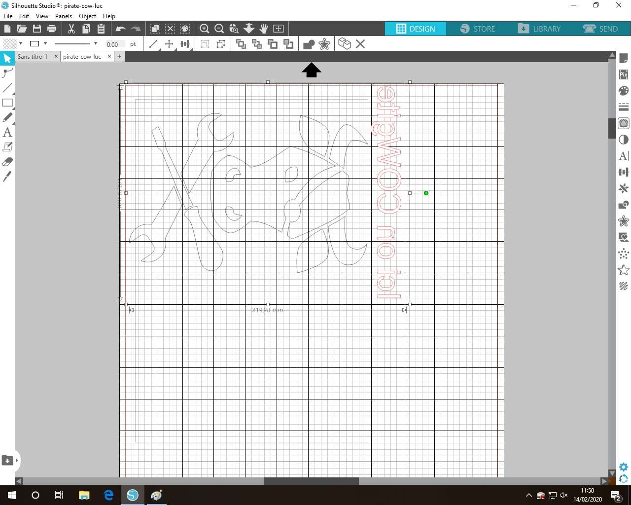
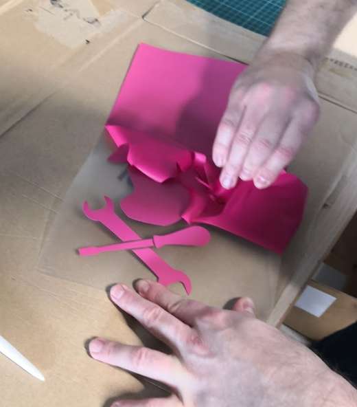
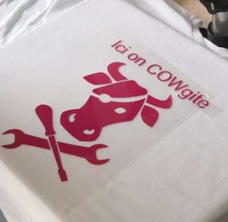
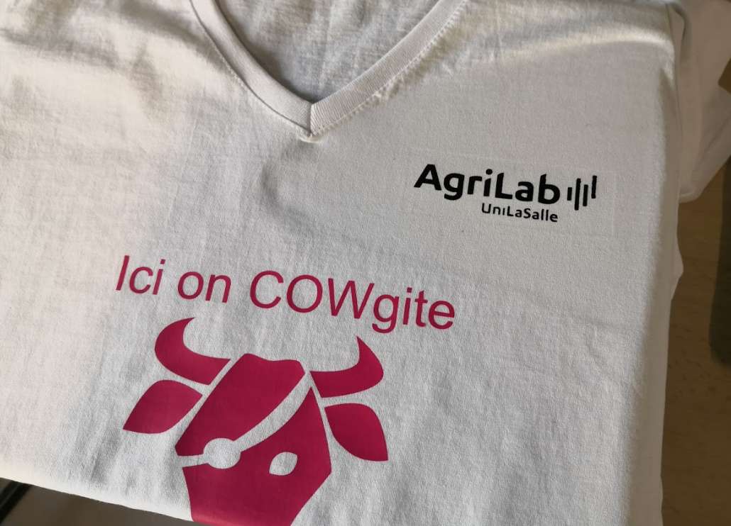
For the SIA (Paris International Agricultural Show) we make custom t-shirts. Here I will make one for a colleague. She wants to reuse the cow made by Luc last year, so we take it and add short text.
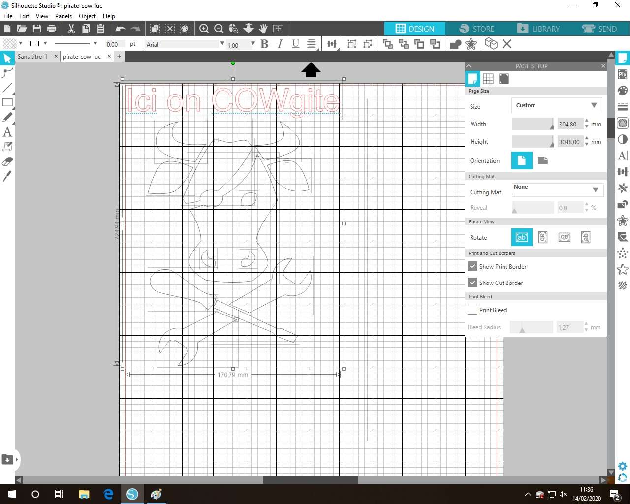
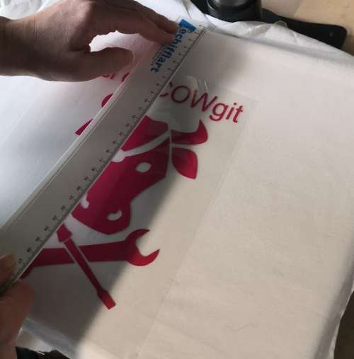
Text and image are align centered.
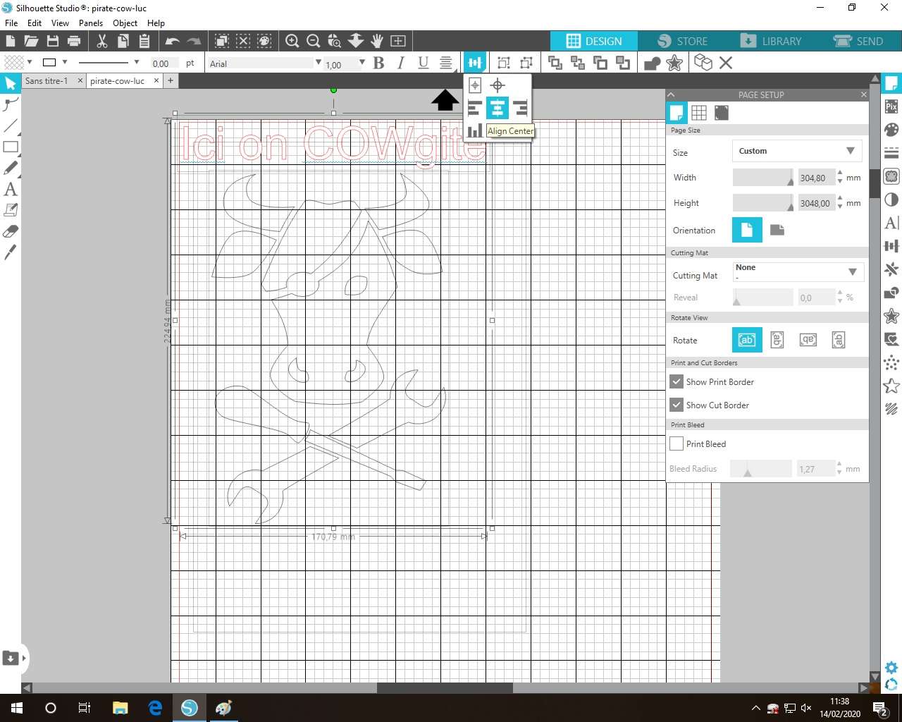
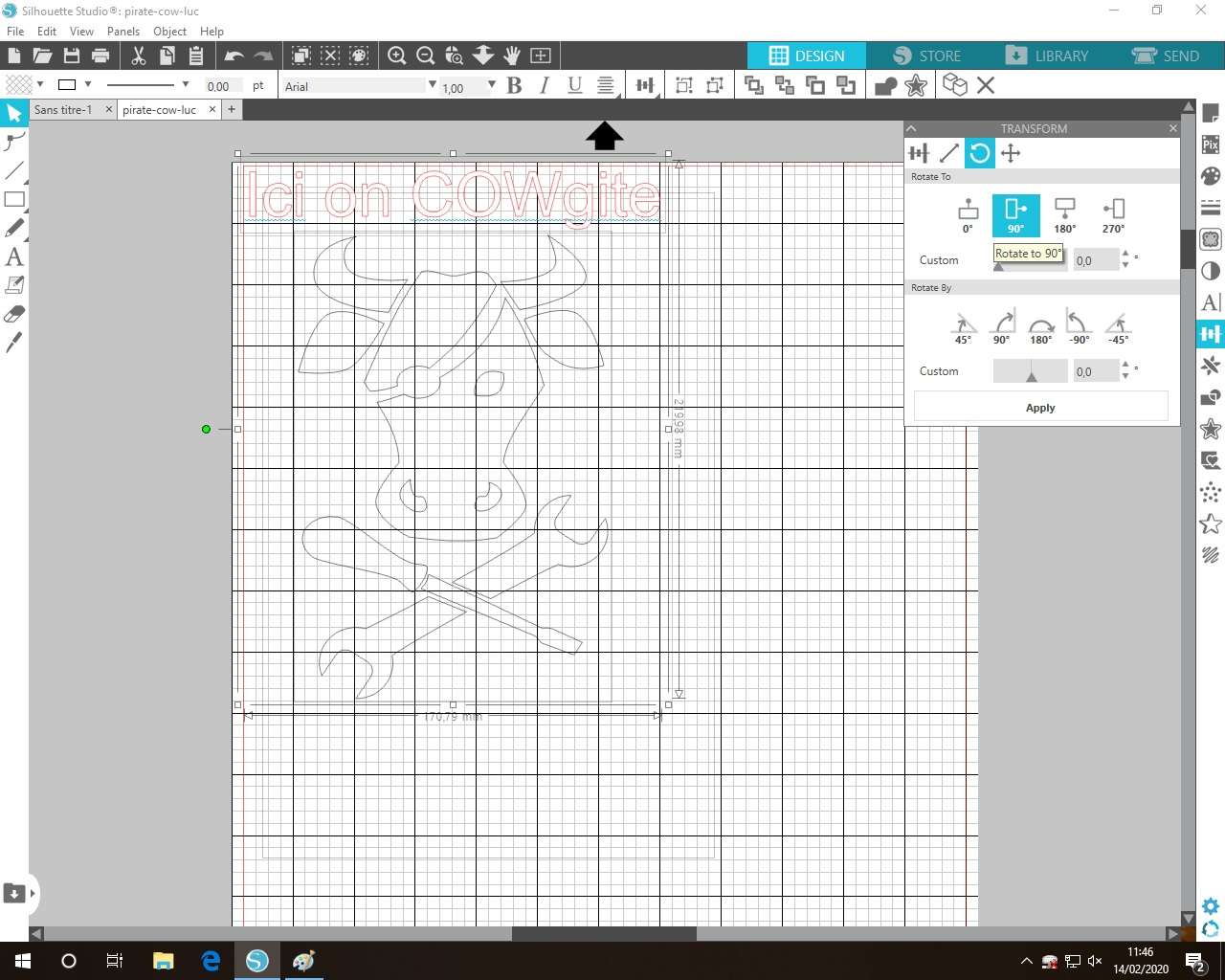
To lost less as possible material, shapes need to be rotated to use max of the width, so I group them.
Why ? 2 reasons :
- I take this habit because usually the vinyl is a roll and because the Cameo 3 (you can see on pictures of machine a little lower on this page) use only 3 little drive rollers, so you can’t reuse too small pieces as is. You have to use a support and using roll and a support in the same work is stupid, you can’t correctly cut because you will have 2 different heights in the same work.
- and also vinyl is billed on length used on the roll, we don’t care is you use all the width or not.
And rotate all to 90°
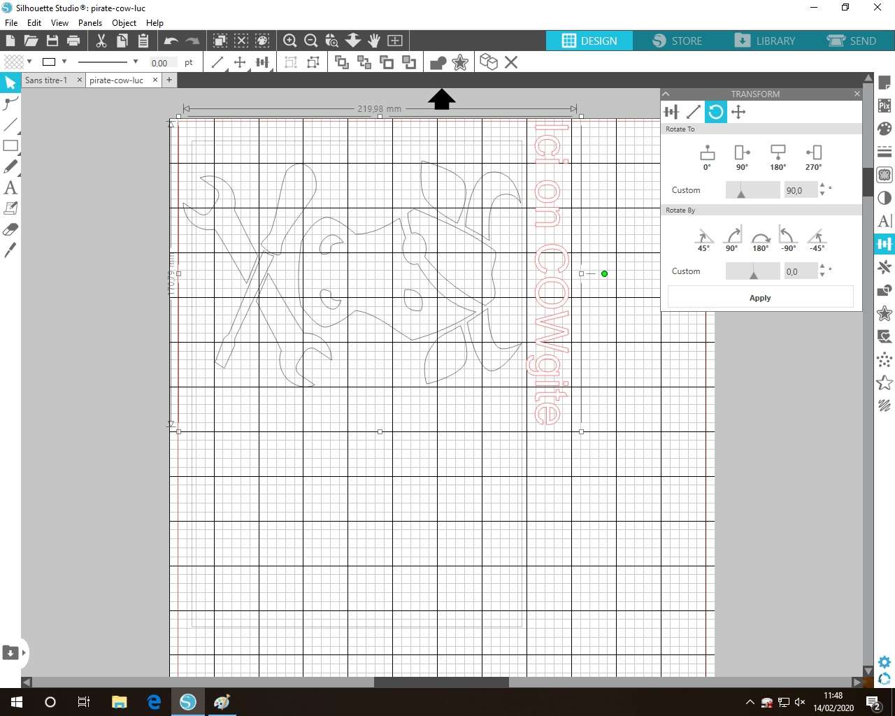
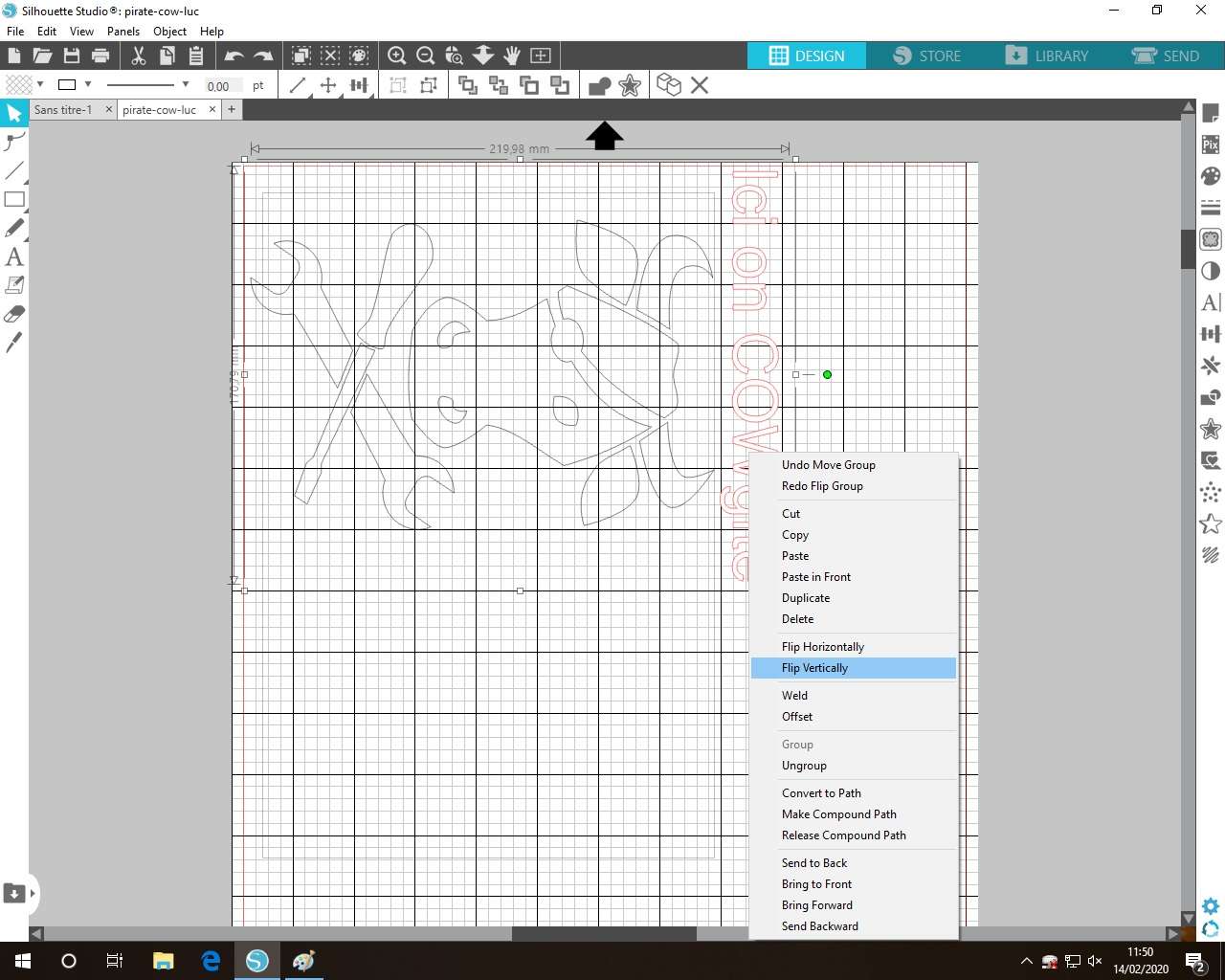
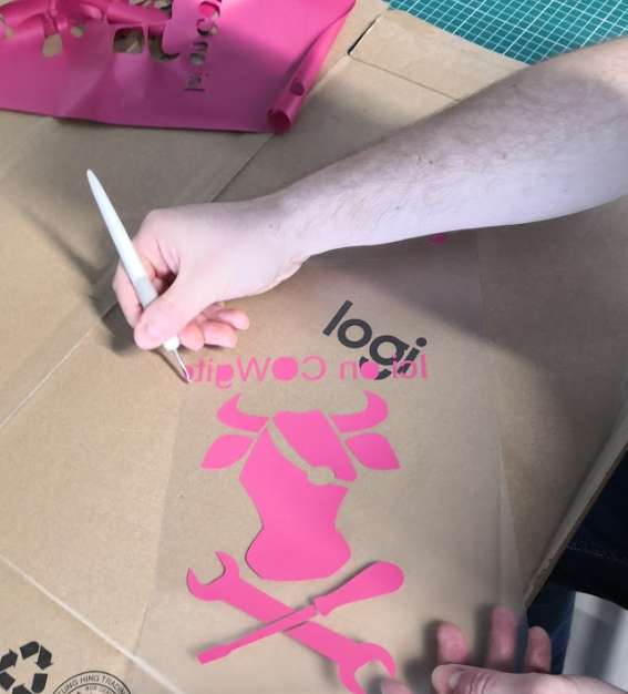
And for heat transfer, we have to flip or text will be inverted !!!
Now, it’s ready to cut so let’s set the cutting. For this we use the autoblade at 1, we cut all at speed 5, force 10 and 1 pass.
Why this settings? With this value, it cuts vinyl but not the support layer.
-
If you not cut enough, unwanted vinyl can’t be removed from support, try again!
-
If you cut too deep, vinyl is fully cut but also the start of support layer and when you remove vinyl, the support tears off in the same time and it’s hard to correctly remove parts
-
If you cut very too deep, all is cut and because of the 3 small drive rollers explained above, the vinyl will not correctly move material and can destroy all your work
Every vinyl brand are different, try your to find correct values!
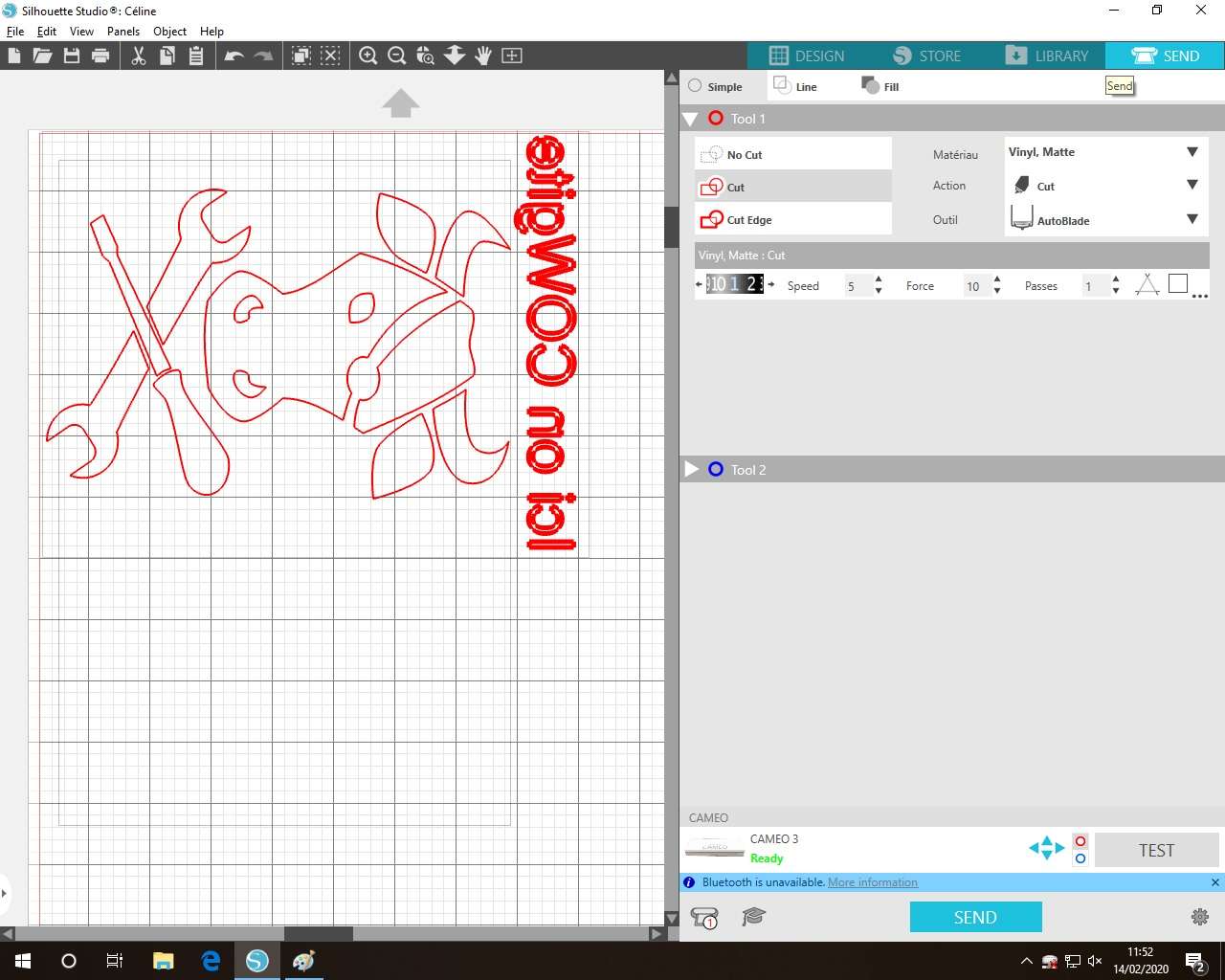
And now, click on SEND.
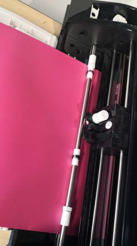
Here the Cameo Silhouette, dual head with an autoblade
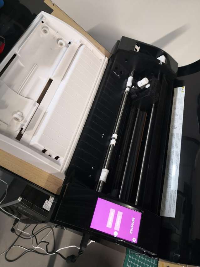
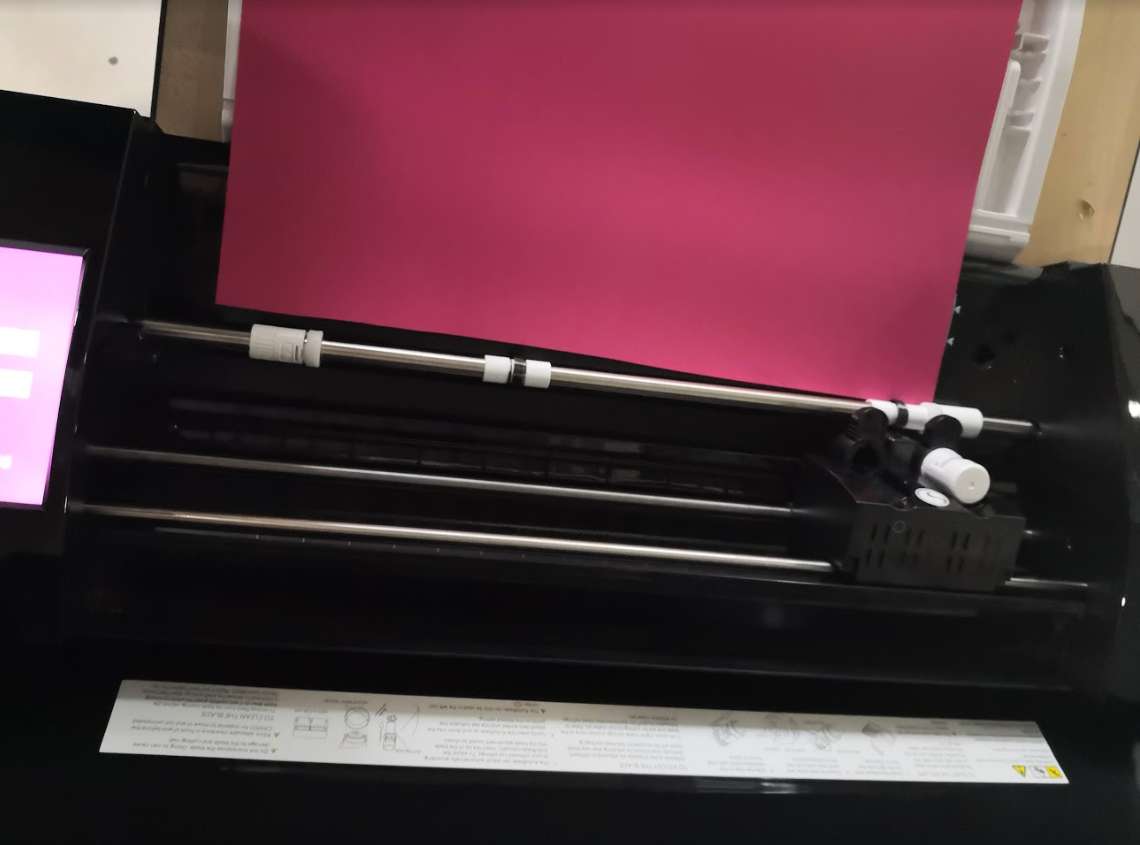
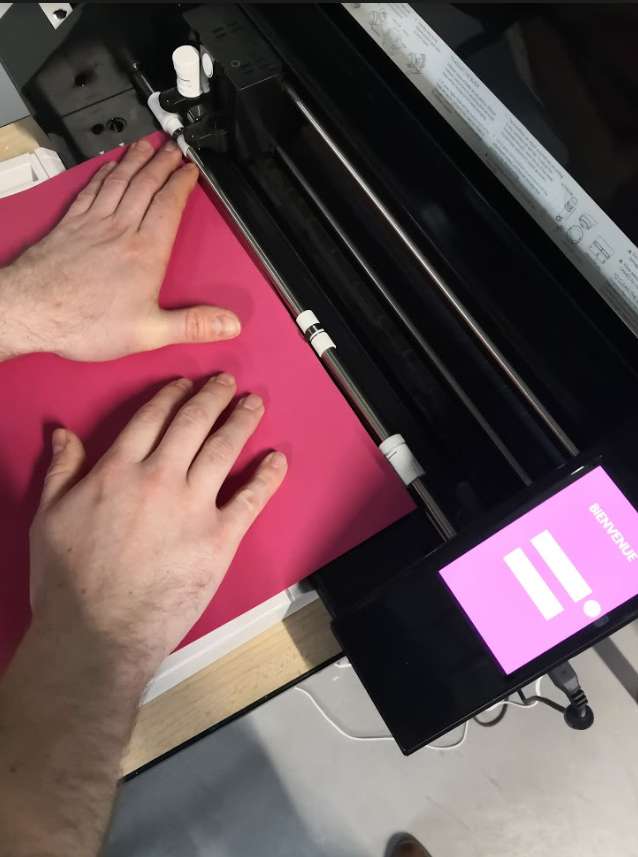
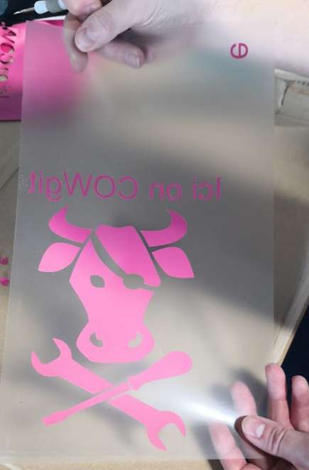
The vinyl we choose is a sample for our supplier, as we can see, it’s not properly cut, so be careful with loading and alignment.
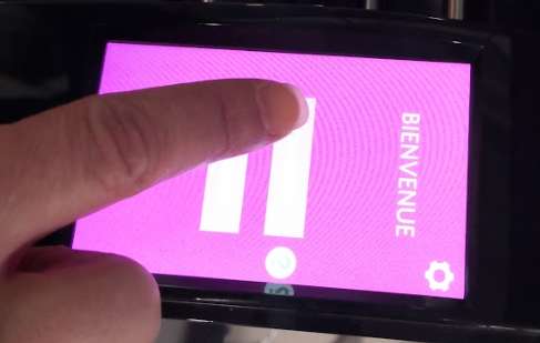
Click on loading on touchscreen
And push correctly vinyl at loading to keep well aligned.
That’s seems good
Now I click SEND of the software.
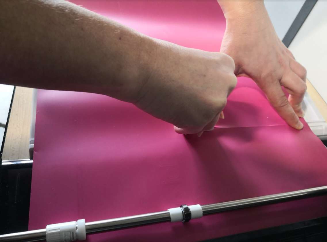
Cutting is finished so I cut Vinyl and after click on touchscreen to unload.
Oooh, text was incorrectly cut on one letter (loaded too short) so back to software and create just the letter. I reuse the vinyl to cut the missing letter on a free part.
I remove unnecessary pieces
And it’s done, we can see the “e” letter on top, we put it on the good place after.
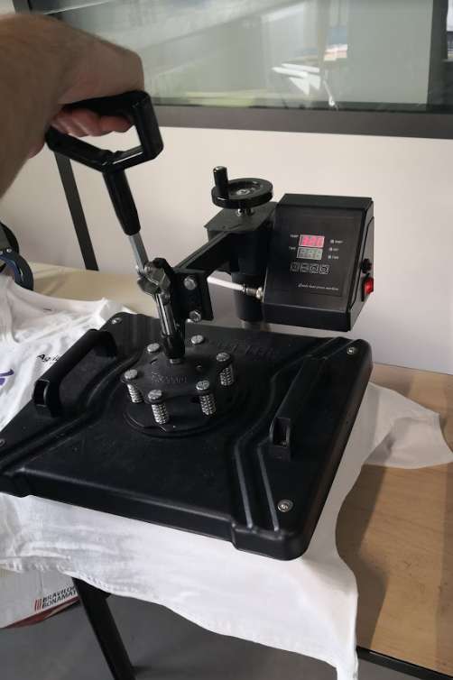
Now I use the heat press machine, it’s a Chinese cheap machine (so I haven’t any spec on it). I put a first time the T-shirt only to plane it.
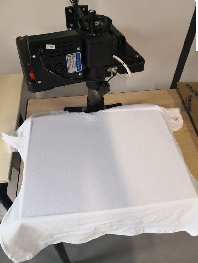
I measure to correctly align vinyl
And adding the “e” letter at the correct place :)
I press and launch timer. Usually, I use 321°F and 45s. (These value was found by doing many tests last year with vinyl roll we have at AgriLab) With this sample used for the first time, I need to double time so 1m30 (I started first by using same values but vinyl didn’t stick to fabric, I test the grip by removing gently support on one corner, so I relaunch right after with a second run and it was perfect).
Now it’s time to add the AgriLab logo, I do it manually this time. i put it on the t-shirt.
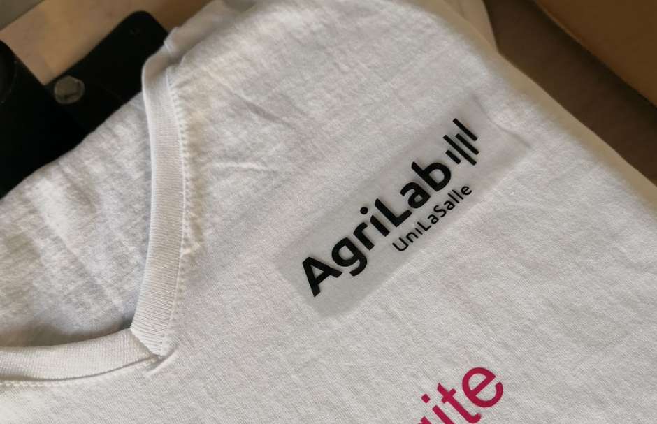
I use here an iron because I can’t pass again on already heated vinyl.
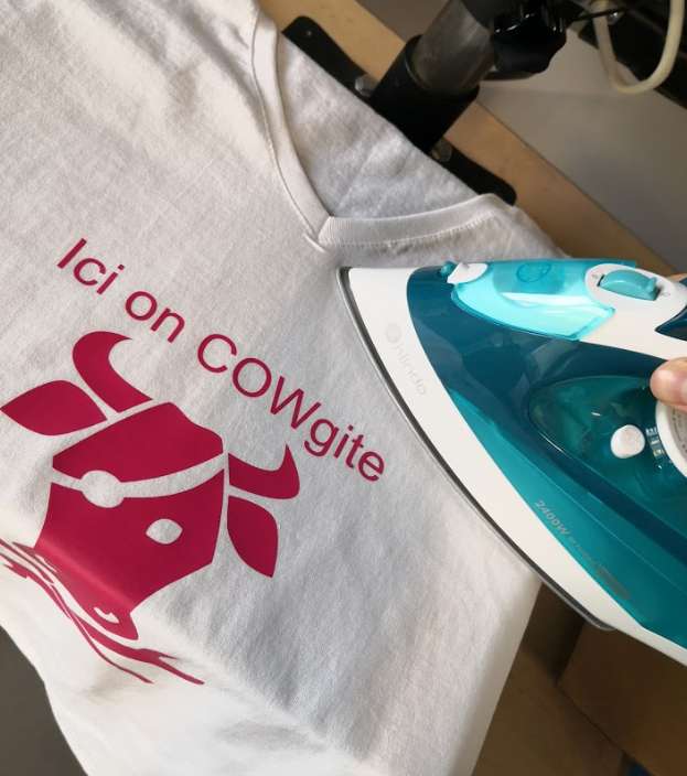
And voilà
Adhesive vinyl
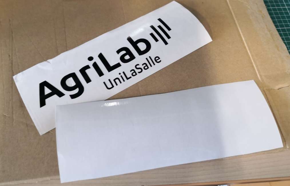
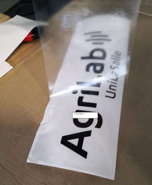
This time, I will put sticker on a laptop. First I add AgriLab logo on the software, It’s already a vector. I load the black vinyl roll on the Silhouette.
No need to flip this time (because here sticky part is on support side unlike heat transfert vinyl). After removing unwanted parts, I cut transfer vinyl at the same size.
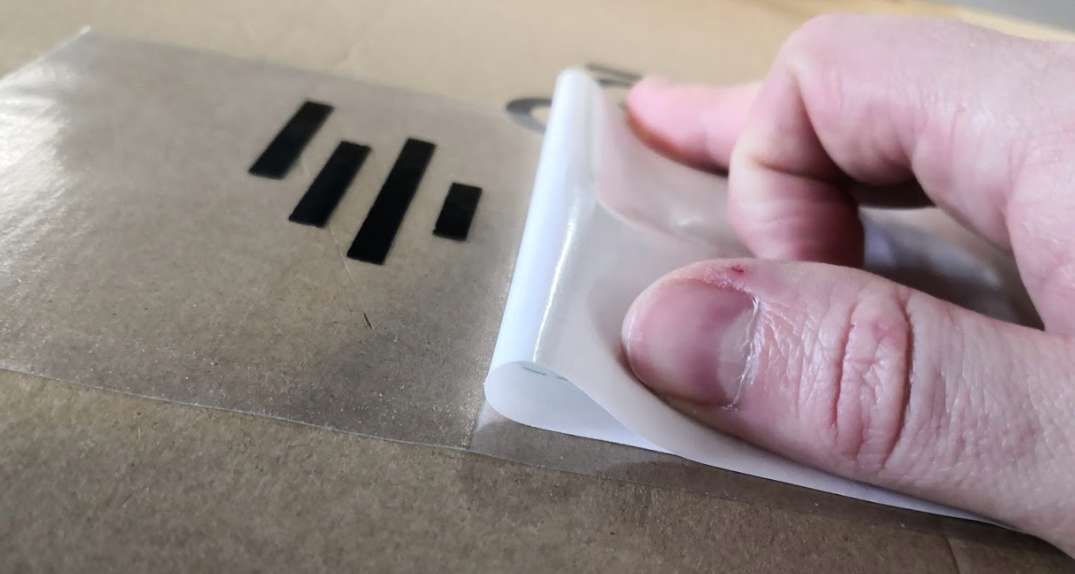
I put transfer on vinyl (first you remove transfer from his own support and put on vinyl, you need to firmly press)
I remove the under layer to let vinyl on transfer, for this I bend layer for easy removal.
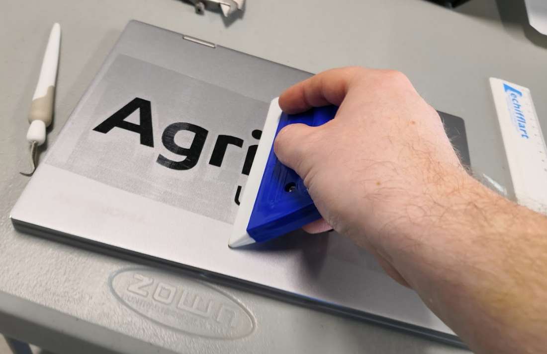
I put vinyl + transfer on the laptop and firmly press
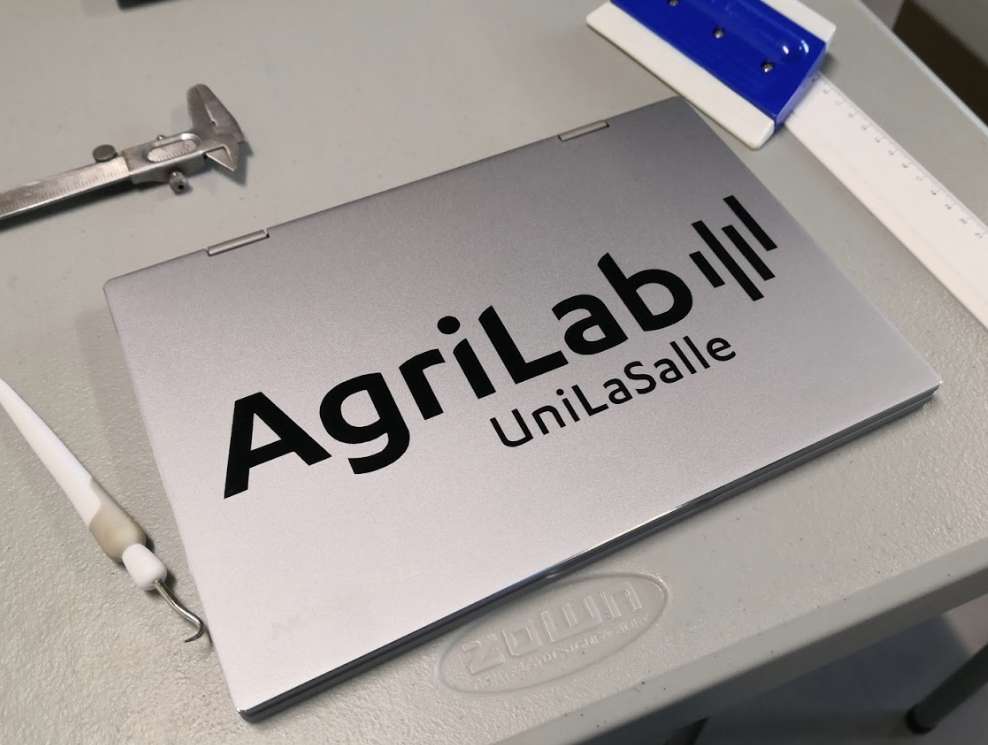
After removing the transfer, here the result
Laser
Characterizing of machine
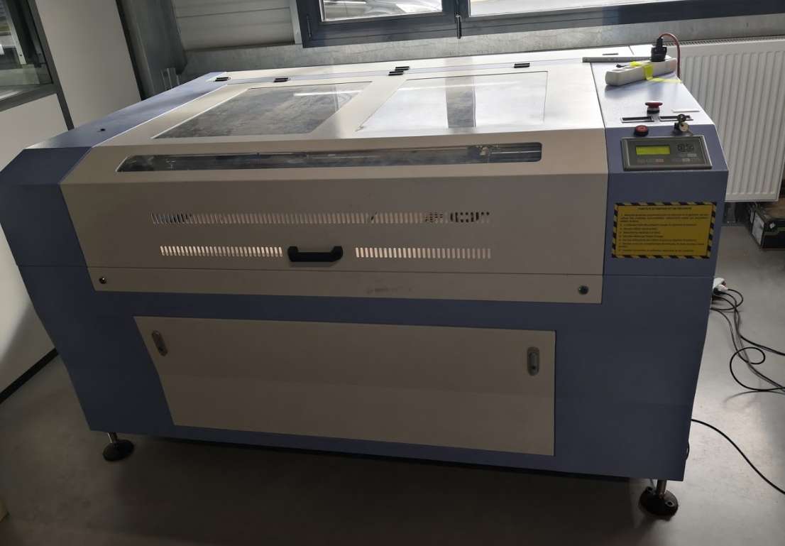
Presentation of laser cutter
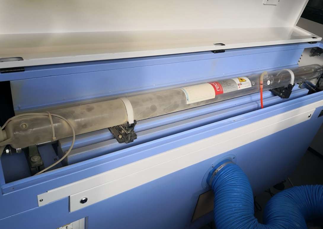
The model is a “cheap” Chinese Laser Cutter CO2 model, CE compliant modified and rebranded under MlLaser name. It’s a 150 Watt CO2 Tube. The Laser Cutter is composed of several units : The LaserCutter , an external exhaust , a watercooling system and an air pump.
The CO2 laser tube at the back (a little bit dirty )
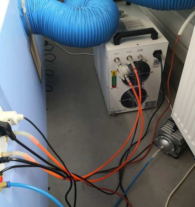
The air pump and the watercooling
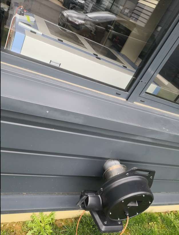
The external extractor
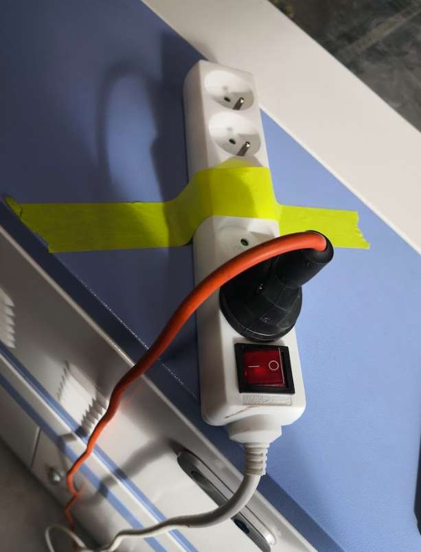
The wonderful manual extractor command
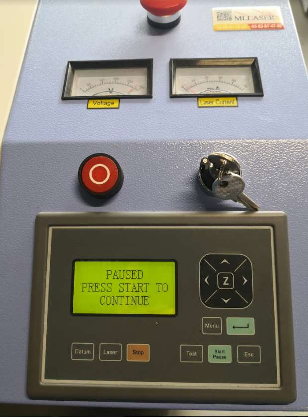
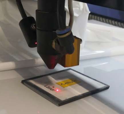
The control panel. The laser button is normally deactivated, for this test I reactive it.
The software
The machine works with Lasercut 6.1, a common software for many Chinese CO2 Laser.
It import files in formats like .dxf or .ai , but not .svg
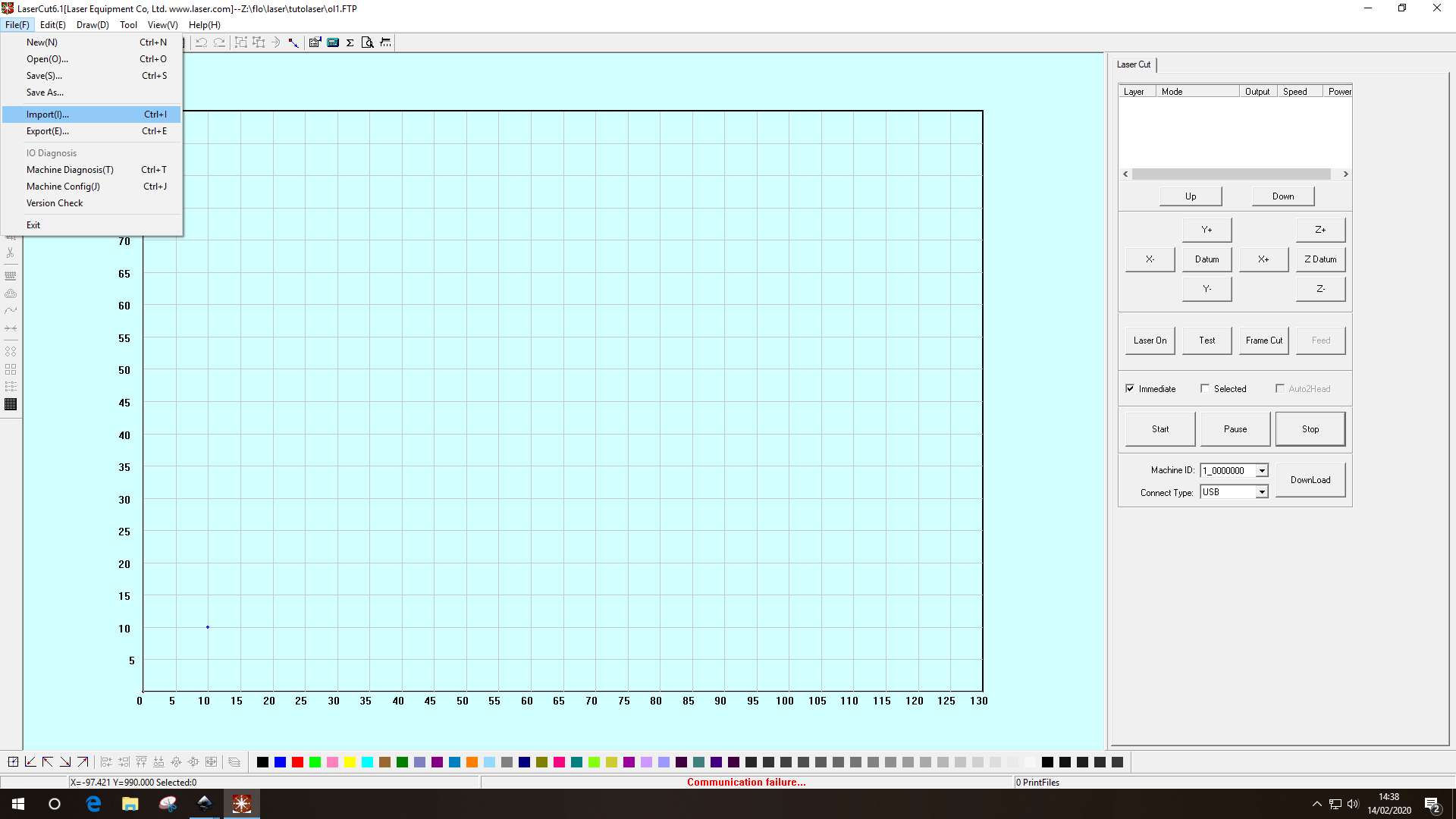
You assign settings with colors. Each color matches to a layer. For each layer you can assign mode (engrave or cut), power, speed and so on. This 2 mode’s names are a little confusing and I have to explain carefully to AgriLab’s members this part.
Cut : it just follow a line, you can assign it to lines, no need to close shapes. Cut no just cut, it also engrave, just depends on settings.
Engrave : it fills a surface, it work only on closed shapes (or you will have some strange results). You can also cut if you use wrong settings (too much power, not enough speed) but what a waste of time, I strongly recommend to use cut.
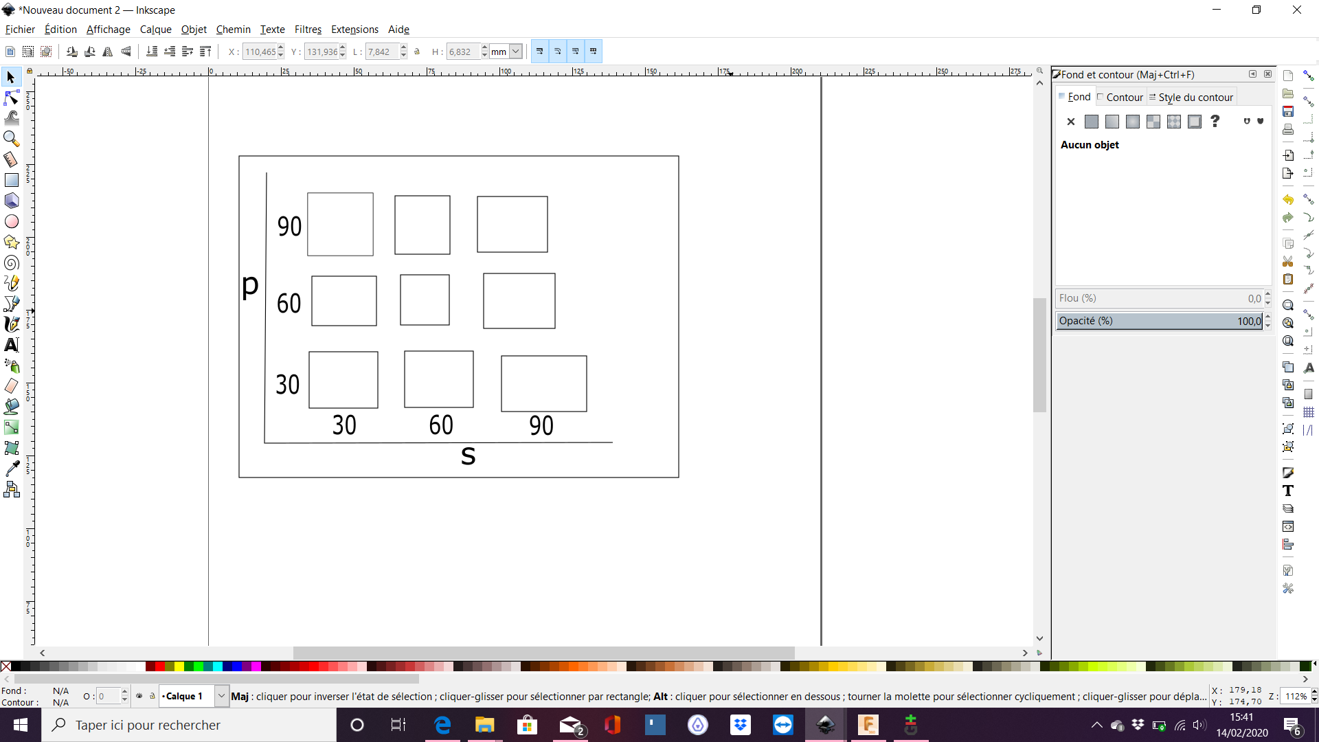
I recommend using Inkscape before Lasercut. You can put directly colors here when design (and remember colors matches layers in Lasercut) and after your layers will be automatically created in Lasercut when importing dxf files, you will just have to put correct settings on each layers.
I also simulate lasercut result of you design with inkscape : use edge color (and no fill color) to simulate cut use fill color to simulate engrave (and you will see weird result on shapes not correctly closed)
Cut configuration
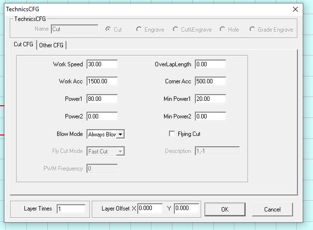
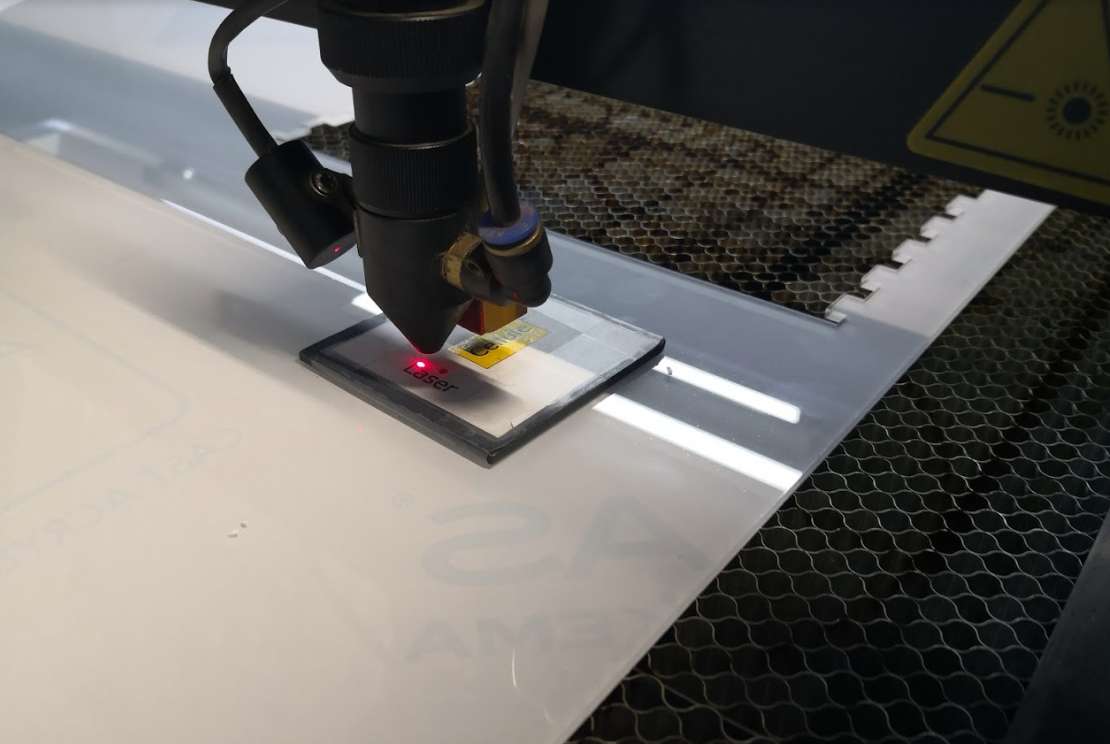
Focus testing
The laser cut had a automatic Z leveling. Head have a inductive probe at the back, just put a metal plate on the material and launch auto Z leveling.
Is auto leveling correct? I’ve tested it.
For testing this, I take measure with caliper. In order to have enough space, I have to temporary modify the machine.
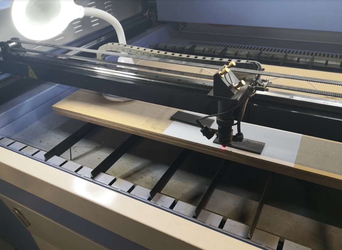
Because I have removed the honeycomb tray, I’m too short on Z axis, so I put some MDF to raise. During test, I have seen machine have a security after auto leveling, it’s impossible to raise the tray after, only lower it. It’s OK to test focus only in one direction, I have to bypass that!
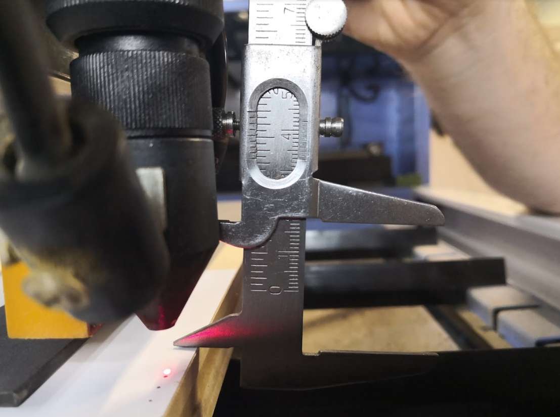
How? after auto level, I measure with a caliper. Then I simulate a fake Z by holding the plate much lower than my real height on an empty space. After I replace manually Z at the “autofocus height”, after I can go up and down because machine think my Z is much lower.
My tests with manual levels, green is the normal autofocus level. Point are from left to right, higher to lower tray level. Smaller point is better.
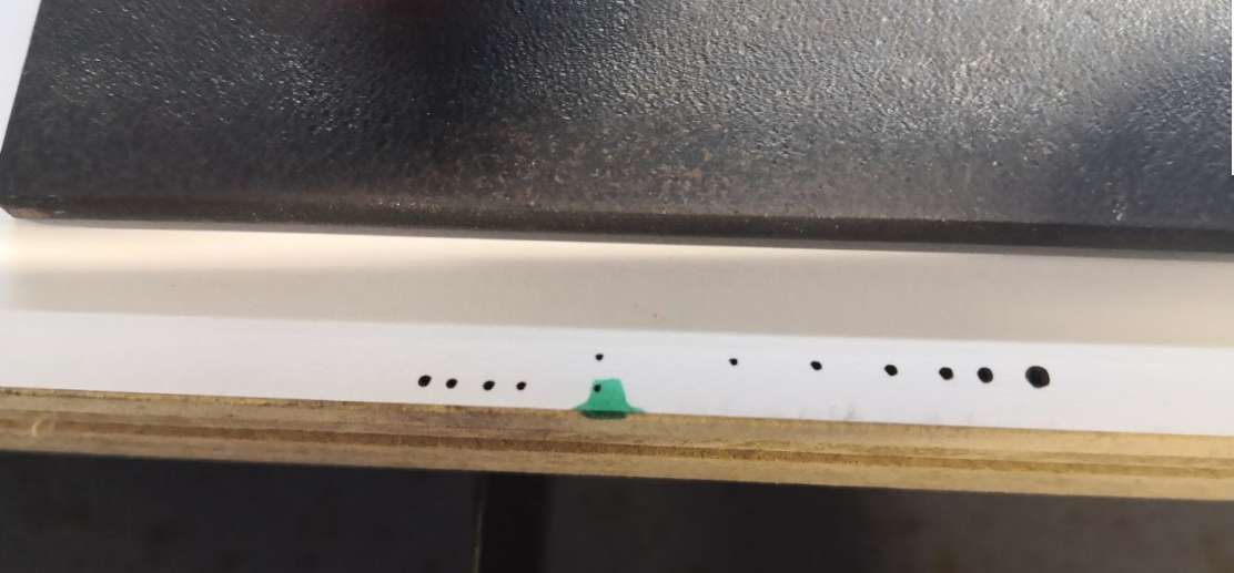
Measuring heights (I’m using a fixed point on the head, the air blow tube because I can’t go between nozzle and material)
I can assume that auto level make the best kerf at the top of material.
Kerf testing
Kerf is the measurement of the space freed up by the material which is burned by the laser.
When you cut one time, the space is too small to be precisely measured.
To reduce measure errors, we decided to do it 10 times, and divide the total space by 10.
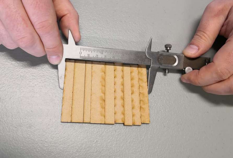
The difference, for 10 cuts is 2,5 mm so our measurement defines a free space (kerf) of 0.25 mm for one cut.
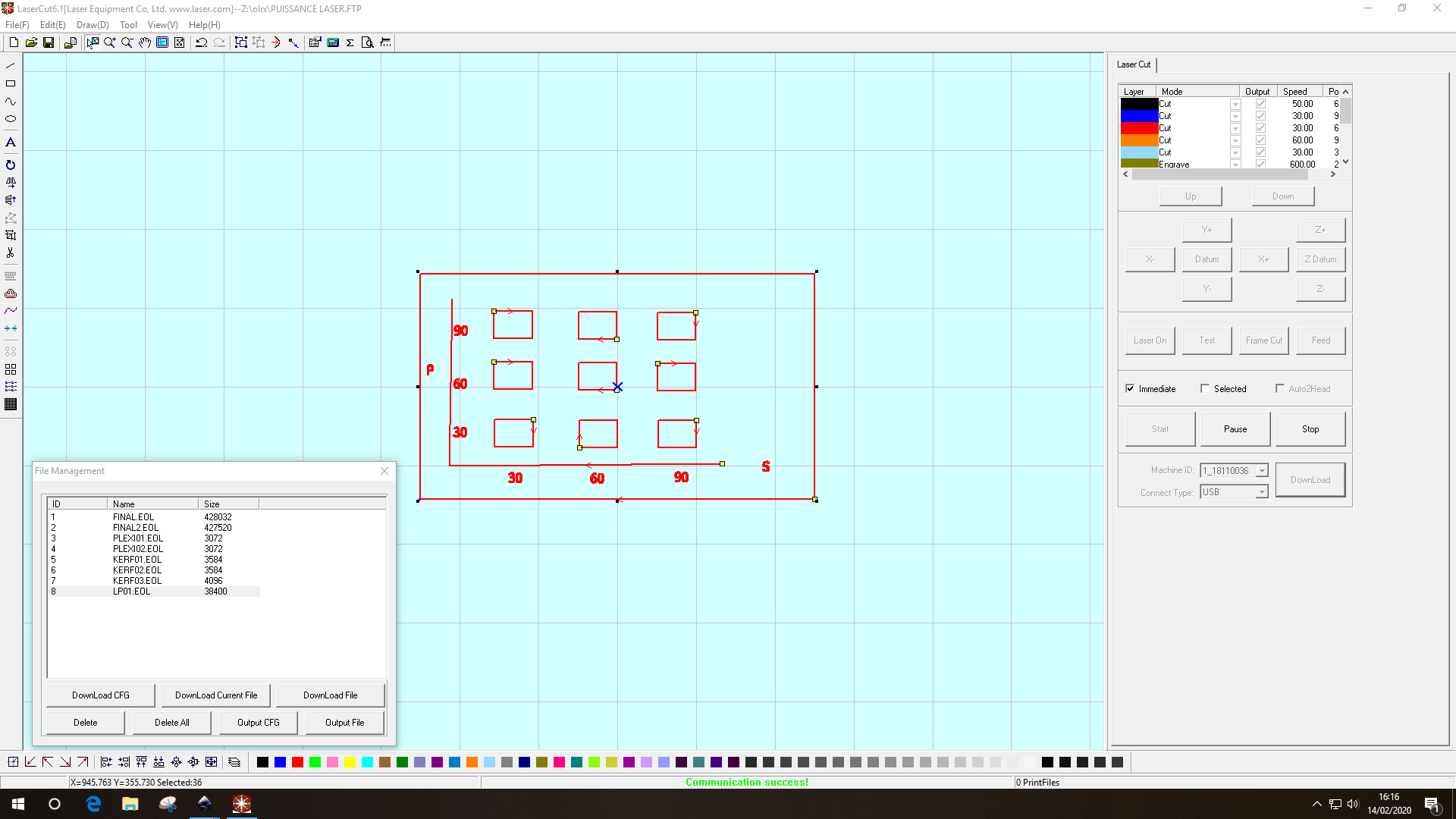
Power testing
we tried to make a useful documentation for the users of the laser cut.
the speed and the power required depend on the material to be cut.
We tried with cardboard 3mm, PMT 3 and 6 mm
the result
The outline has been cut with 100% power, 20% speed for the PMT 6 mm.
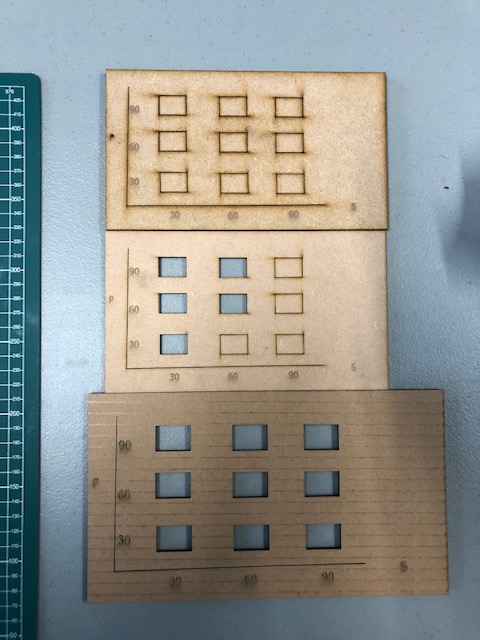
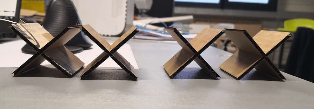
Joint testing
For this, I use the FreeCAD file of the course : joints.FCStd
I found cardboard measured with caliper at 3mm.
I have tested slot and chamfer.
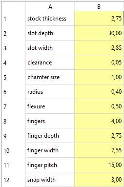
File is a bit weird because we can’t set kerf, so I have to adjust thickness and remove kerf in it. Chamber sketch is not fully parametric since slot depth are not plugged to spreadsheet unlike slot sketch.
Here values I finally use
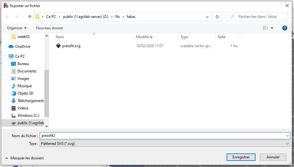
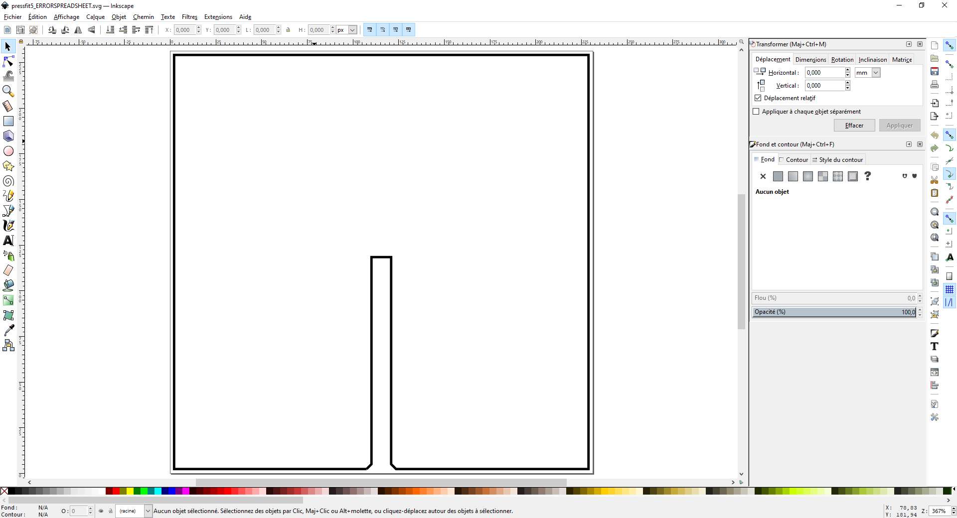
For cutting, I need DXF. I have never successfully export directly freecad sketches in DXF, I have to export in flattened SVG, open in Inkscape and convert to DXF. Such a pain!
How I found these values? I tried many versions and keep the version where I can easily assemble it and also doesn’t disassemble on its own. Also remember here, it’s cardboard, I won’t use same settings with another materials because of rigidity and friction of each material or the way it react on laser. I will use smaller slot with cardboard than PMT because cardboard is more flexible. It also depends on the complexity of the final object.
Using PMMA
I also cut PMMA sheet
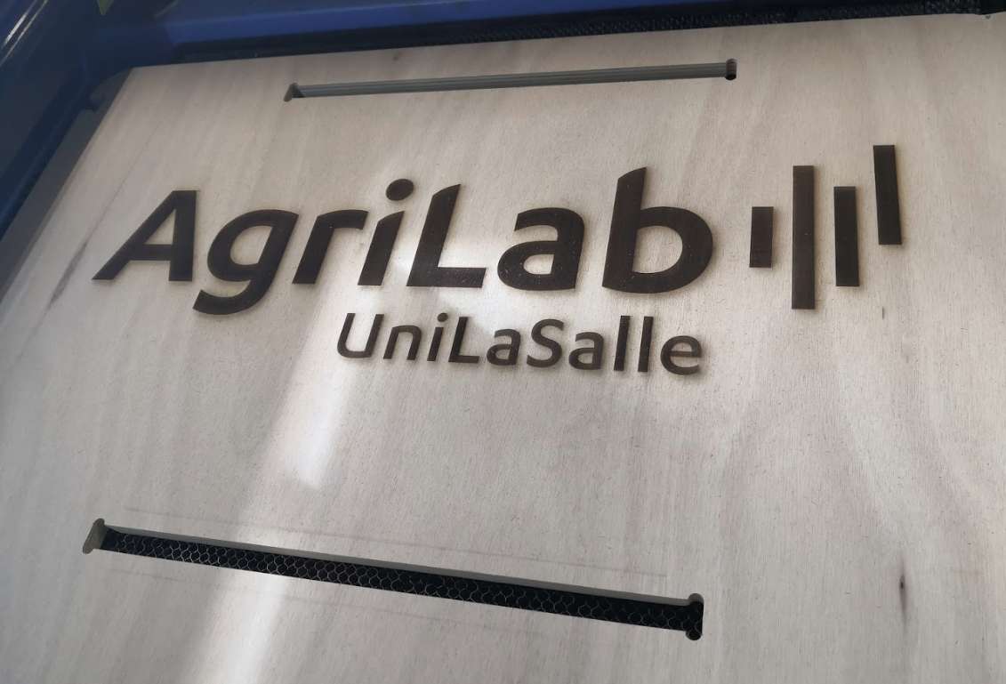
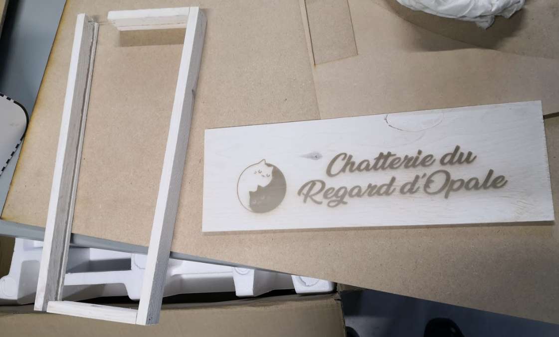
Plywood engraving
I helped colleague to engrave plywood panel for our stand at SIA.
Assignment : Construction kit
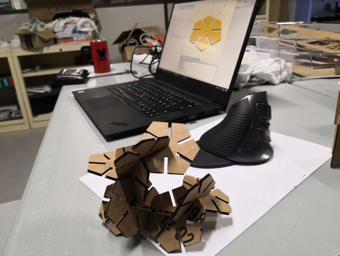
For the design, I will use my favorite software I have briefly showed in week 3 : OpenSCAD I love use it to quickly make parametric design, as a former developer it’s quicker than standard CAD for me (keyboard is faster than mouse, like command line VS GUI)
You can find cheatsheet here if you forget something.
And with a few lines of code I made from scratch :
//parameters
// sizes are in mm
edges = 6;
diameter = 60;
thickness = 3;
clearance = 0.127;
slotLength = 20;
kerf = 0.255;
// code
$fn = edges;
buildObject();
module buildObject() {
difference() {
circle(d=diameter);
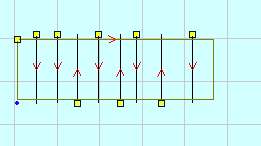
for (p = [0:edges-1]) {
rotate([0,0,p*360/edges]) {
translate([0,(diameter/2)-slotLength,0])
square([thickness+clearance-kerf, slotLength]);
}
}};
};
I have a fully parametric design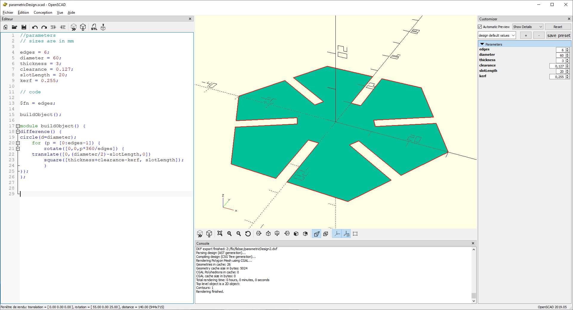
I can directly export in DXF and import in lasercut software, so perfect !
I use pattern to directly insert 10 copies. Here the cutted cardboard :
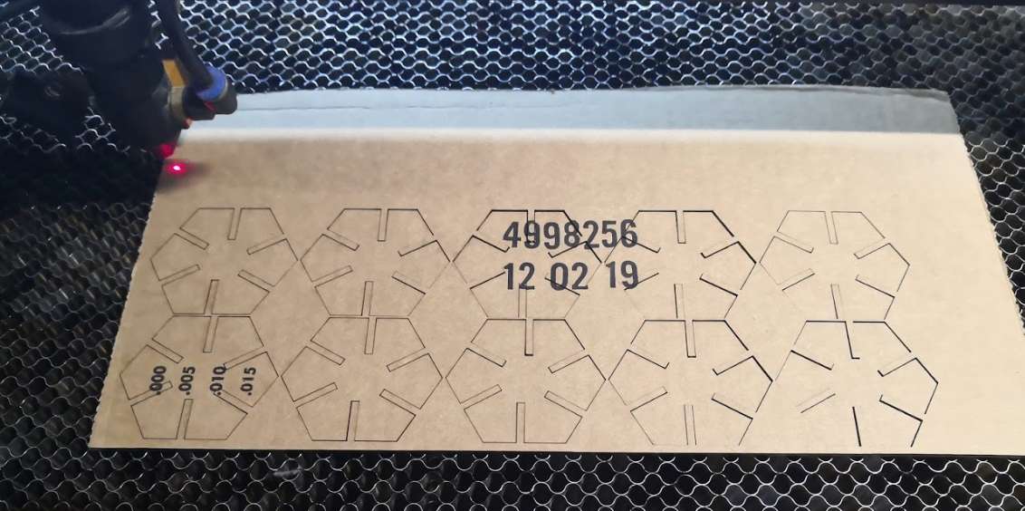
And the result mounted
Laser Bonus : Other makes
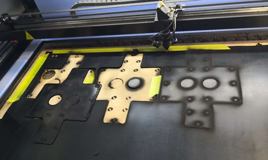
Rubber gaskets
3D design
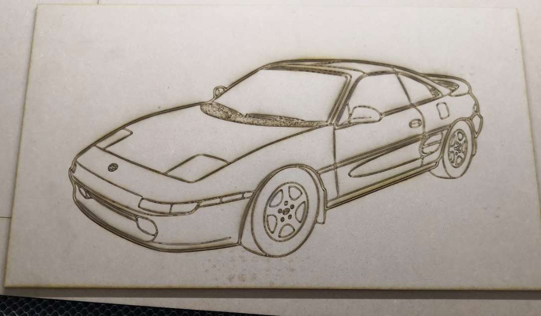
Engraving
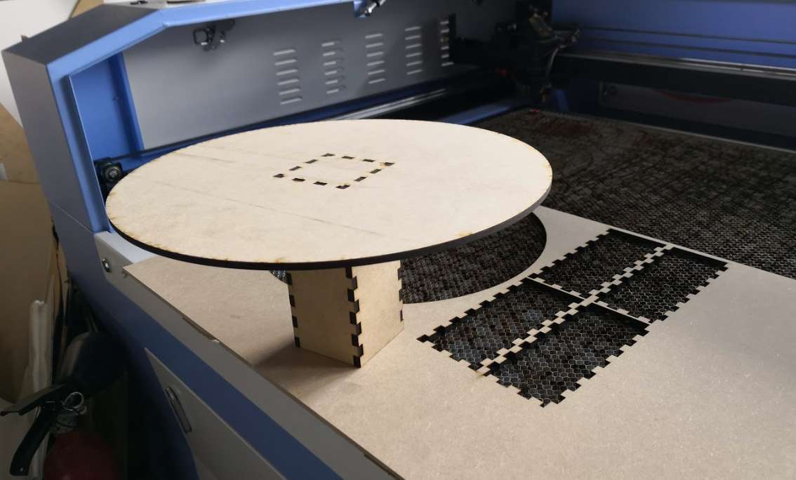
Custom supports
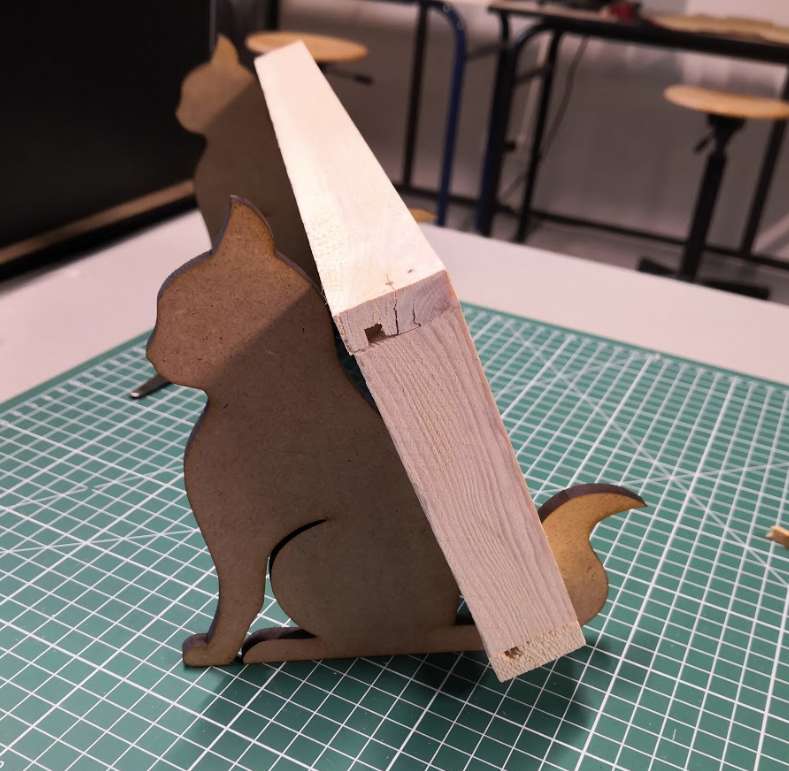
One of my cars :)