5. Electronics production
group assignment :
characterize the design rules for your PCB production process
The material
The milling machine
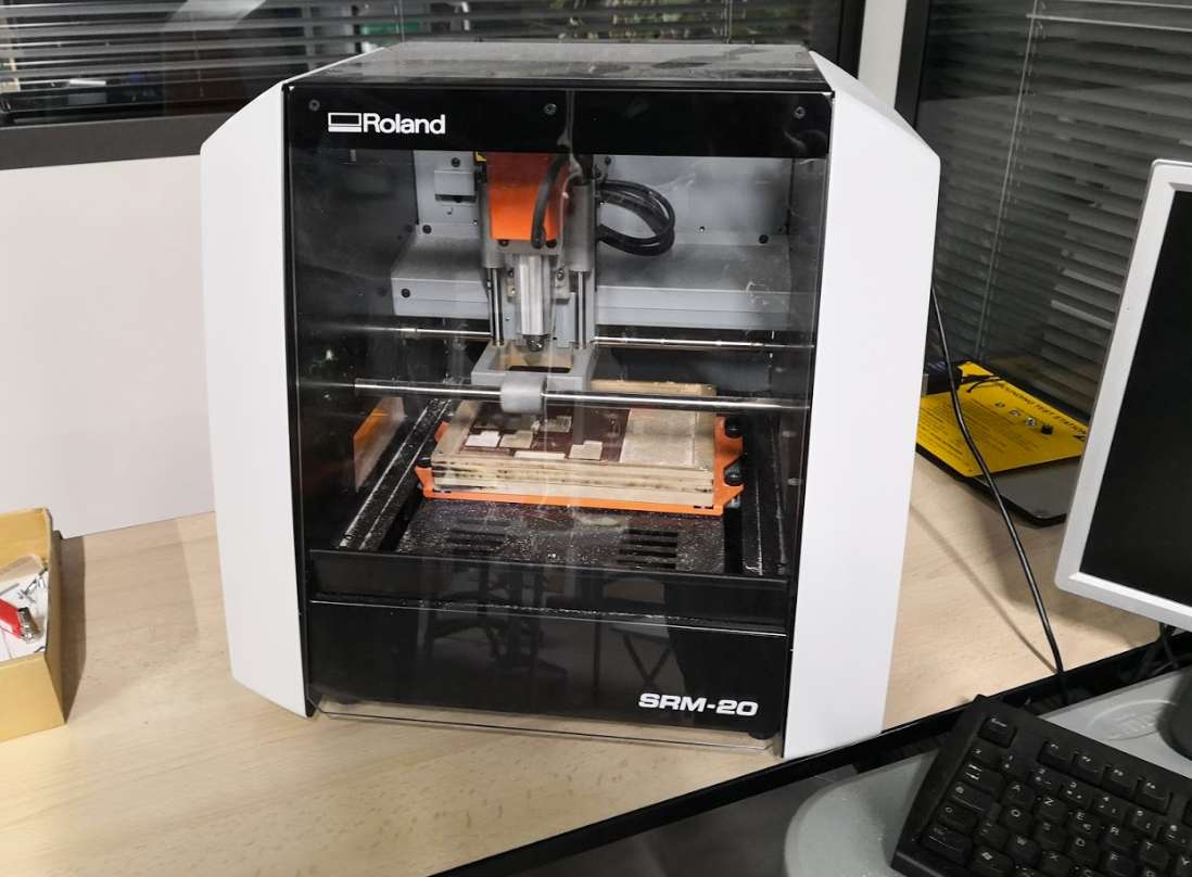
We use the Roland SRM 20. the machine can mill Modeling Wax, Chemical Wood, Foam, Acrylic, Poly acetate, ABS, PC board (PCB)
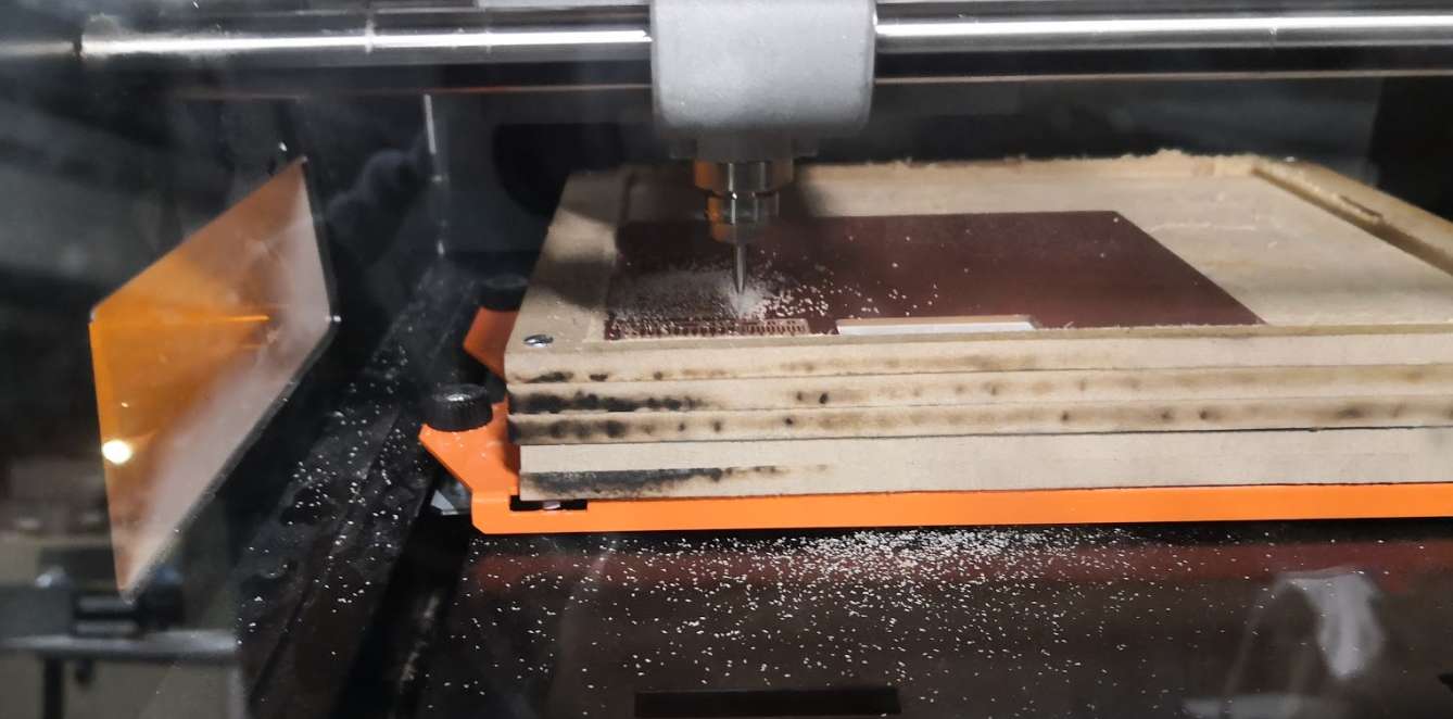
0,4 or 1 mm endmill is short and, even with the lowest position, the spindle cannot reach the PCB blank on the table. You need some extra spacers. We do that with several MDF joined layers, which become the sacrificial board when the milling is too deep.
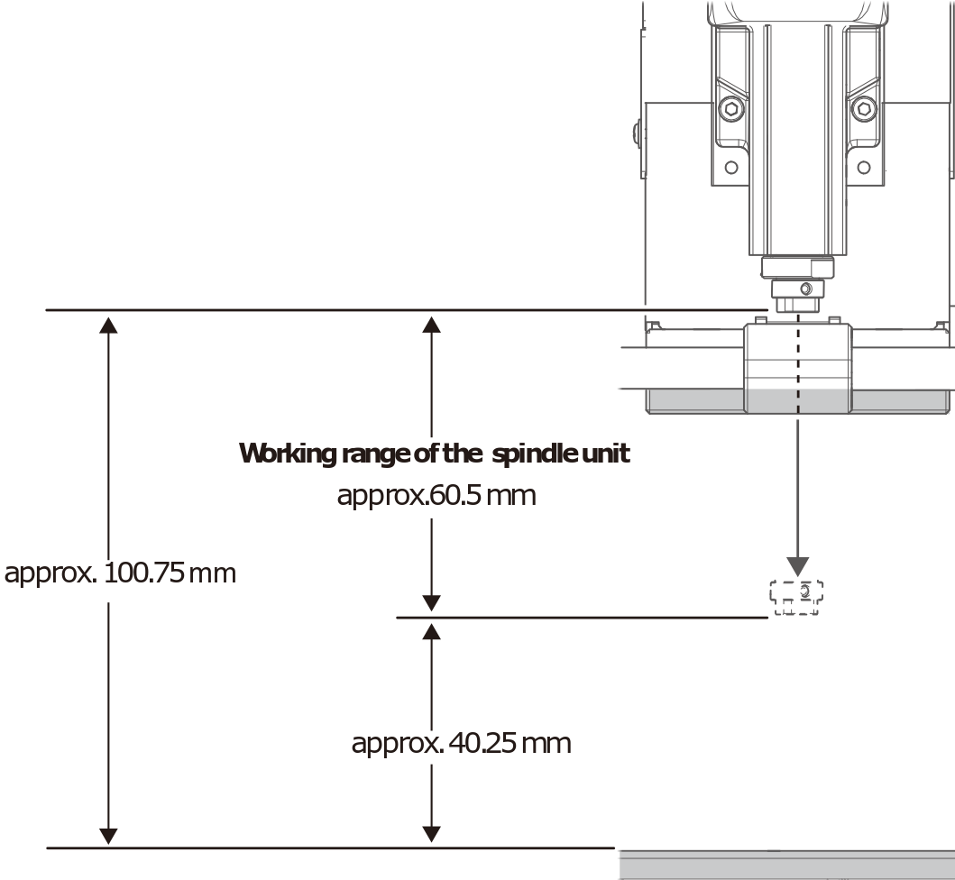
(Credits : Roland)
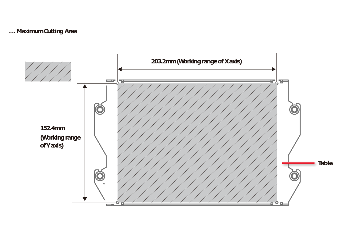
(Credits : Roland)
You have to be careful when you install the endmill because it’s very fragile. Don’t let it fall.
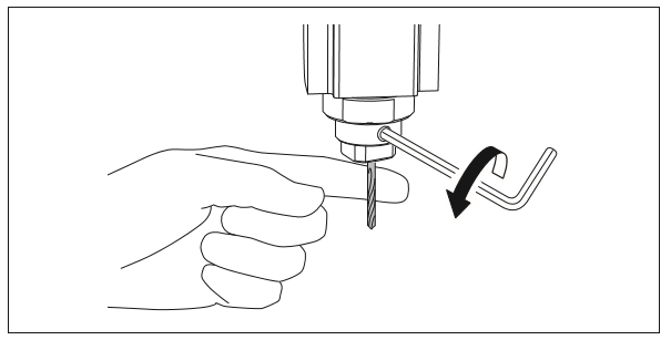
(Credits : Roland)
The machine itself has a “hardware” zero position (x,y and z) but like any CNC machine, you have also to set your job 0 as well, Z is depending on the attachment of the endmill . The x,y depends on where the PCB blank is installed and also depends on your design
This machine accept 2 Languages : RML-1 (Roland standard) .rml , NC code (general language) .nccode
In the specification Roland wrote you can send command to up 0.01mm with RML but with NC code you can go up to 0.001mm SRM-20 specification
Here the workflow :
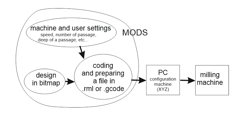
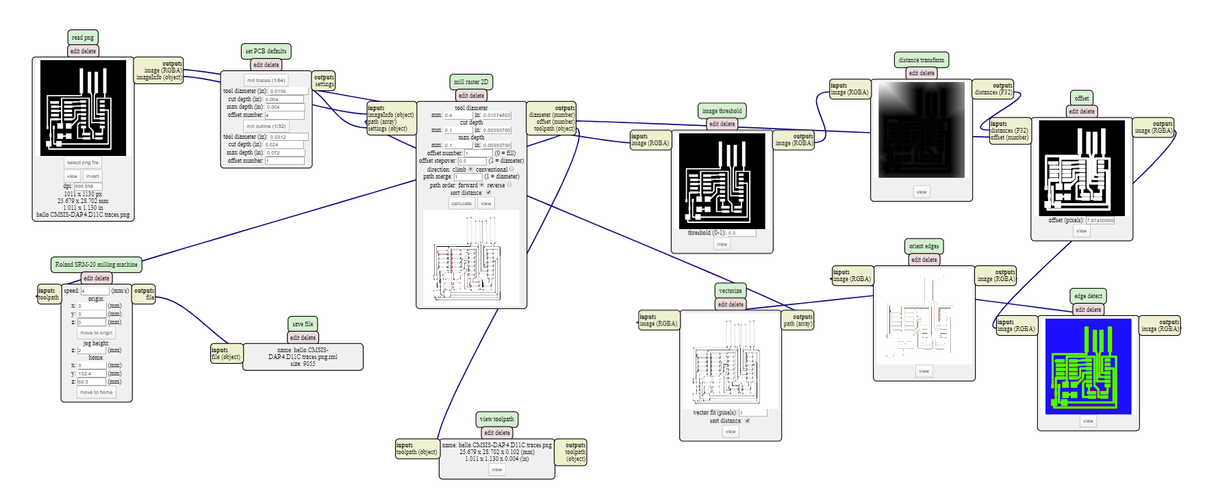
Configuring Mods
We use Mods to generate RML code. Removing websocket and plug file>save module instead at the end of chain. So we can download generated Code to put to Vpanel. The software that control CNC machine.
We use climbing (because Neil says during it gives better result but it can be harder for the endmill), speed 4 mm/s, 0.1 mm depth and a two-flute 0.4 mm endmill. We start to set speed at 50% on Vpanel to be sure, and we increase slowly speed to 100%. Nothing breaks. We keep this values.
For cutting, we use speed 2 mm/s, max depth 1.7mm (PCB blank was measured with caliper at 1.5mm), max cut depth per pass at 0.3 mm and a two-flute 1mm endmill. We start to set speed at 50% on Vpanel to be sure, and we increase slowly speed to 100%. Nothing breaks. We keep this values.
We don’t try to push harder because we have a little challenge at the fablab to don’t break endmill until the end. So we stay safe.
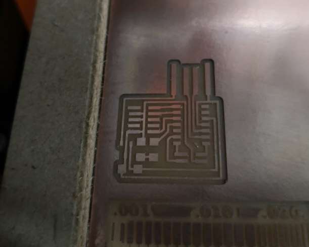
Result of testing
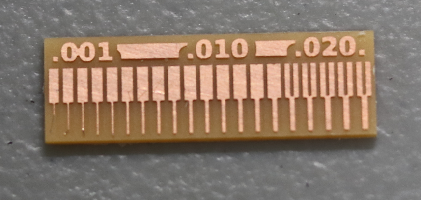
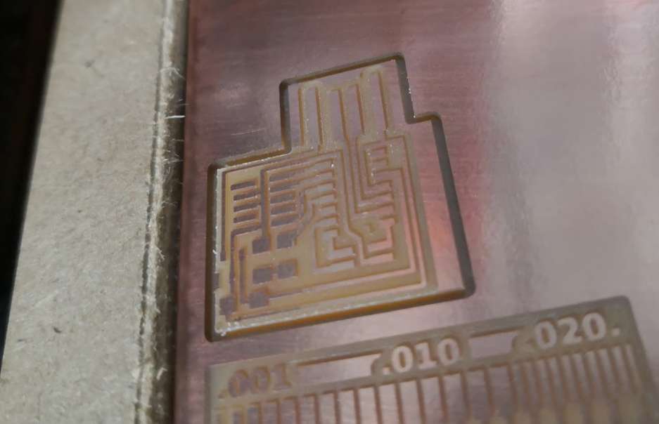
With our settings, results are perfect. But the little defaults on the left (traces from 0.001” to 0.003”) came after touching the PCB with hands, so this size aren’t reliable with our kind of PCB (FR1). Using such little size for line can result on bad connections if copper tears off the support.
Inner cut smaller than 0.016” can’t be milled because of the size of the endmill we have here : 0.4mm (= 0,015748”)
individual assignment :
Make an in-circuit programmer by milling and stuffing the PCB, test it, then optionally try other PCB processes
I choose to make a JTAG programmer : hello-CMSIS-DAP.4.D11C
Why? Because it’s a new one, it seems easier to solder than FTDI and the 4 pin because of the LED (geek inside) Bad idea? We’ll see.
For milling, I use a Roland SRM-20.
For generate MIL code, I use mods.
I have to generate 2 codes, one for the first tool for milling circuit and the other for another tool that will cut out the board.
The board is a FR1 (phenolic resin) PCB with 1 side. I reuse the board used for testing because there’s enough place.
Pictures are a mix of smartphone and reflex (Canon EOS 80D with 50mm fixed zoom).
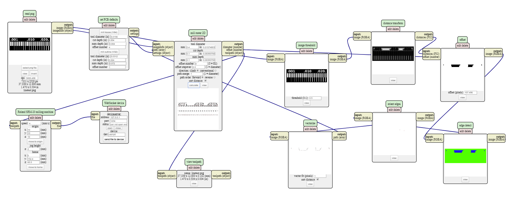
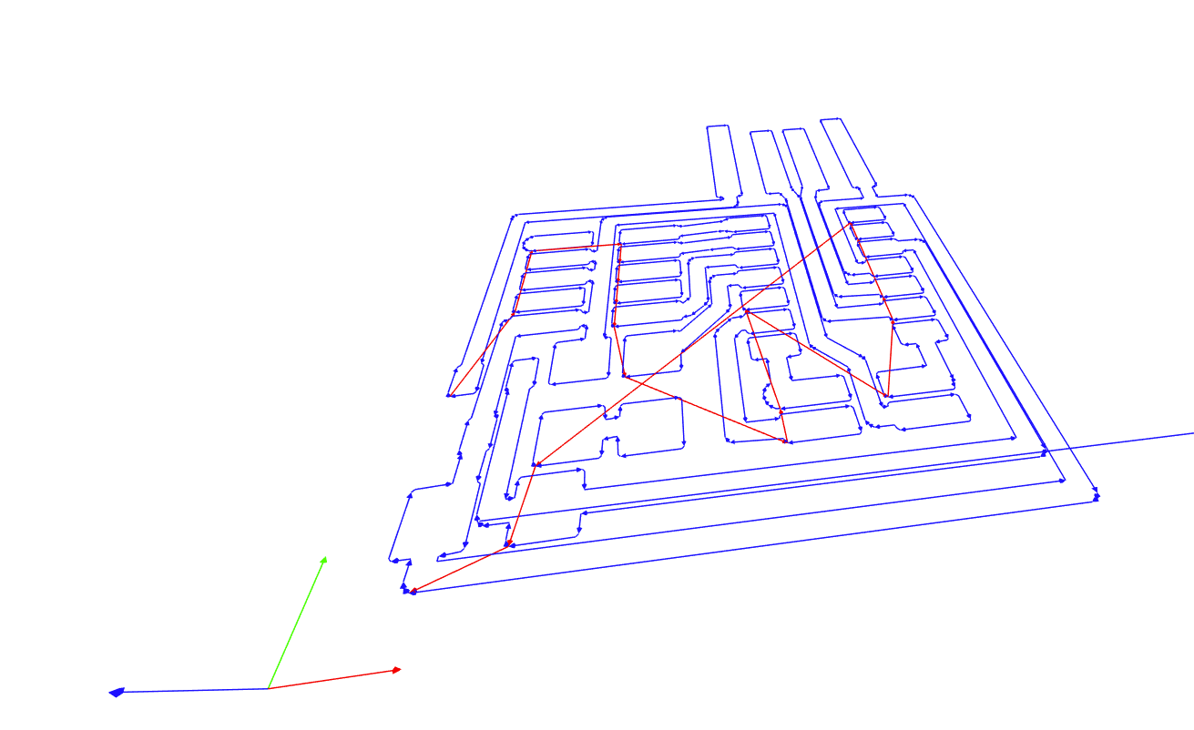
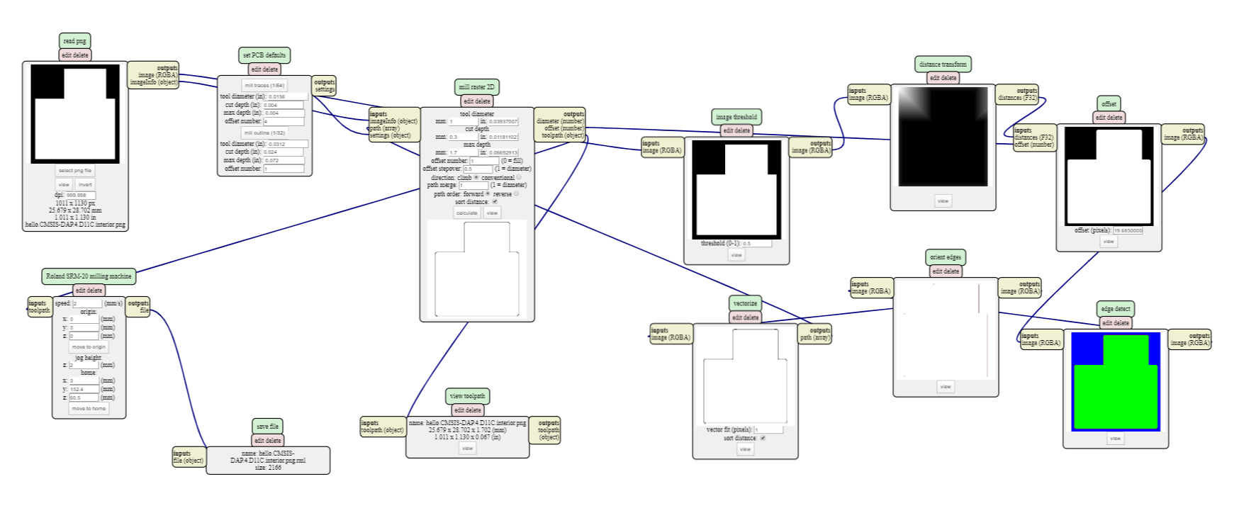
Milling traces
For milling the circuit, I use a 0.4 mm 2 flute endmill. After tests on group assignment, I keep same values that worked great (Challenge is to keep the same 0.4 mm tool till the end). So my speed is set to 4 mm/s and the depth cut is set to 0.1 mm. Spindle speed can’t be set in mods (it will be 8000rpm on the SRM-20).
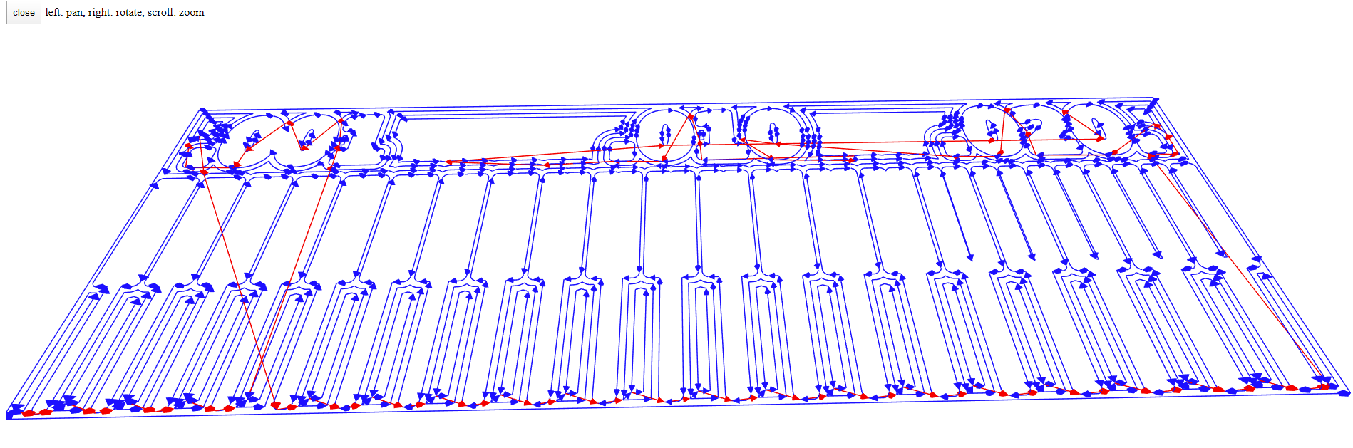
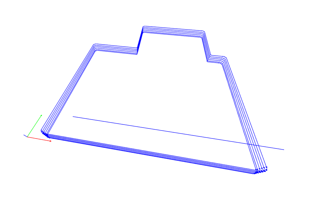
And the simulated path.
Like in group assignment, I remove “webservice socket” and plug “file > save” instead for downloading generated RML files.
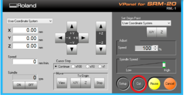
Then I use VPanel for SRM-20 on the computer linked to the milling machine, it will be use for 2 steps
- adjusting the homing of the endmill (on x, y for define start on the PCB, and on z axis because it always changes if I change endmill or material)
- outputing the files to the milling machine
I used double side tape to fix the PCB blank to the sacrificial board. The tape must be laid precisely without bubbles. The PCB blank must be glued as strongly as possible and as horizontal as possible.
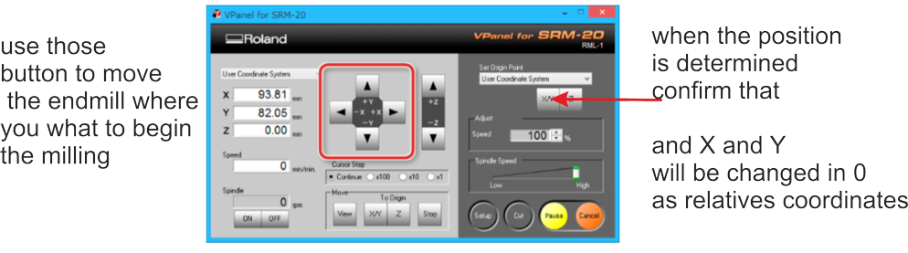
I first move endmill down a little on Z axis I let nearly 1cm, and then I place my X/Y 0 to set start of the work.
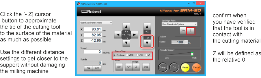
Then I move more in the middle of the PCB and set my Z 0. For that, I start by lower by putting cursor step at x100 (1mm move) and go down, I switch to x10 (0.1mm move) and continue to lower endmill, when I’m near PCB, I switch to x1 (0.01mm move),
.
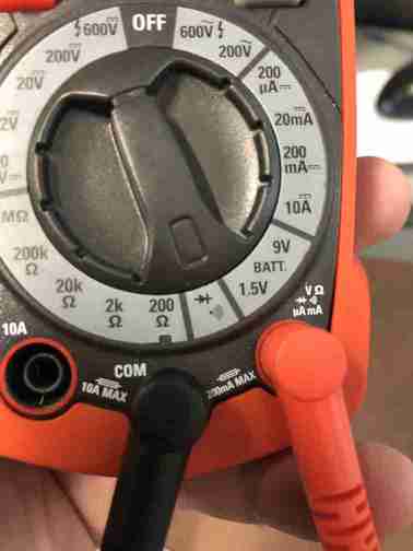
PCB have copper on top, my endmill is metal, so I use electrical continuity to control my Z height.
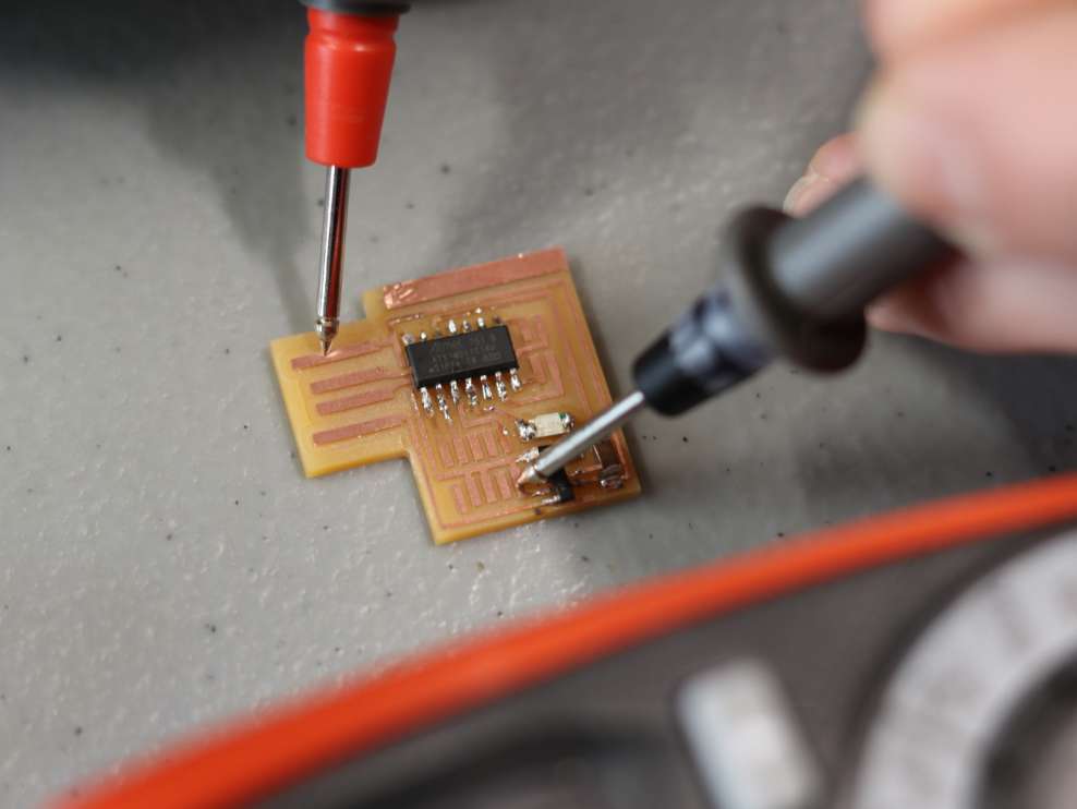
I take a multimeter and put in electrical continuity testing mod (using a multimeter with sound is very helpful for this step)
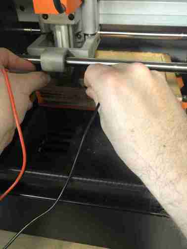
First, I check directly touching red & black pins together and listen the beep. Then I touch the endmill one side and the PCB on other side (I use 2 hands on the picture but I have a technique to take the 2 pins at the same time in one hand so and keep other hand for use the mouse and lower on Z axis) and I lower Z axis (with x1 step) until I listen the beeeeep. Then I go one more time lower (0.01mm because I’m still in x1 step) and press Z button to put 0 on Z axis.
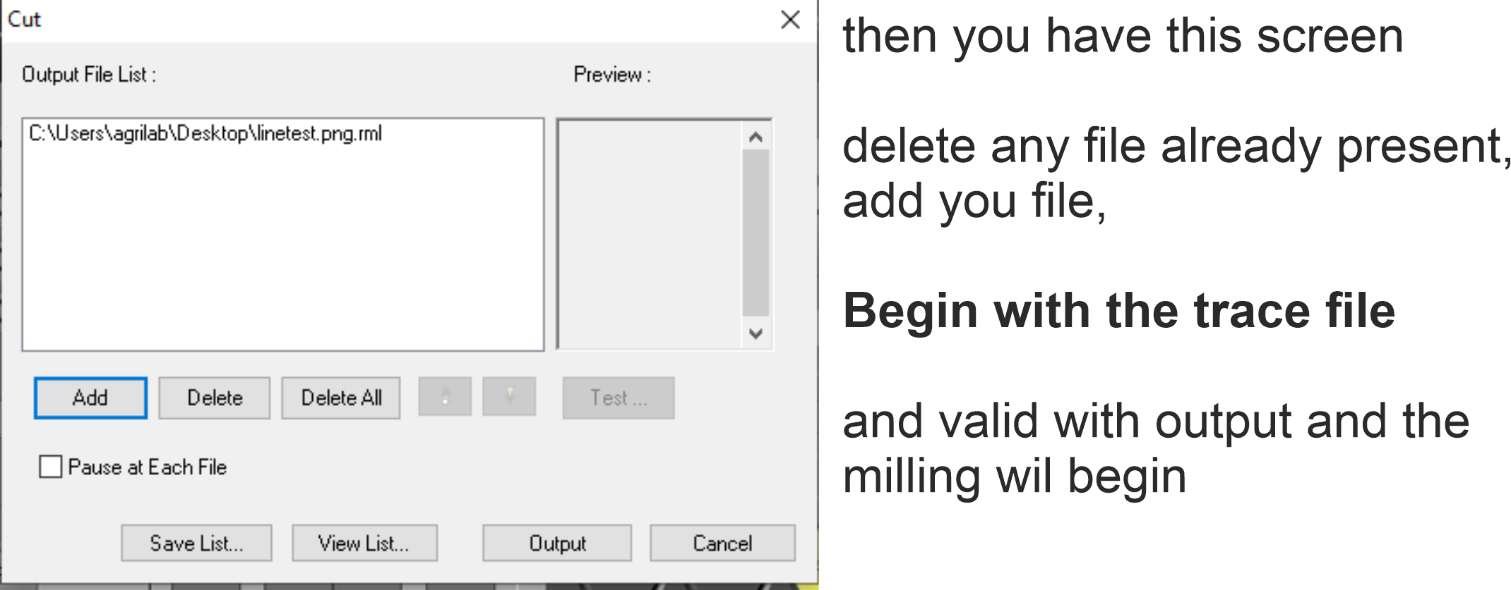
When it’s ok, we can launch the work by using cut button. I add 2 notes for this part :
1/ it won’t work until you close the front door the SRM-20
2/ I take now habit to up a few mm on Z axis before launching the work because spindle will start before moving on axis and… if you let your endmill touch the material, you will have an unwanted hole (and because I set my Z on the middle of my work it can be a big problem if it cuts one trace!)
And the result on the PCB after this first part
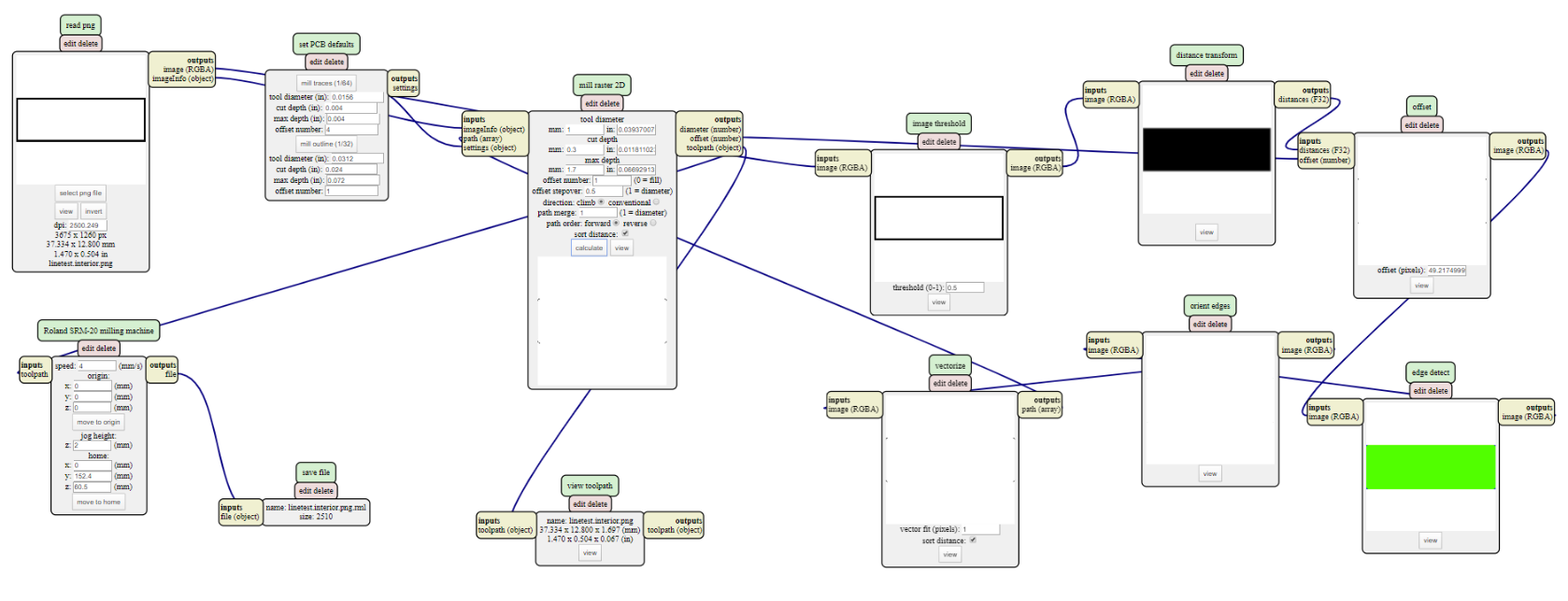
Cutting exterior
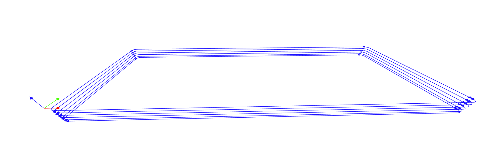
I use a 2 flute 1 mm endmill. The setting I set after testing on group assignment (safe to keep tool ‘til the end, challenge!) are 0.3 mm cut depth per pass, 1.7mm max cut depth (Board thickness was measured with caliper at 1.5mm). I choose this setting to be sure to go trough all material even if the 0 is barely set or the board not absolutely flat. The speed is set to 2 mm/s (Spindle speed 8000rpm).
We can see in the simulation we have 6 passes to complete cutting.
I change endmill on SRM-20, on Vpanel software, I just repeat the Z axis homing part (DON’T TOUCH X/Y homing!!!), I launch work and here the result. I remove my board using a flat screwdriver.
The design provided let some useless copper that need to be removed to avoid electrical issues on USB port with unwanted bridge.
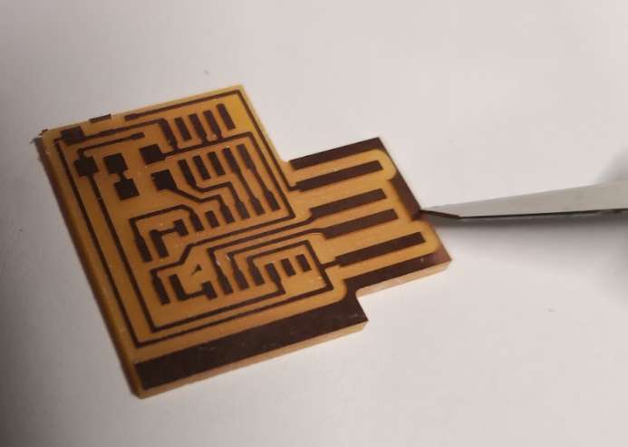
I use a knive to remove those copper parts, here the result after.
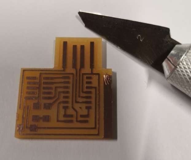
Now, I’m sure I won’t got electrical issue when plug into a USB port.
I see when cutting exterior, because we go trough all, we mill the tape so glu is stick to endmill. As a result, zeroing with multimeter may not work because of lack of contact between metal parts so I spray glu remover and cleaning endmill, it works great!
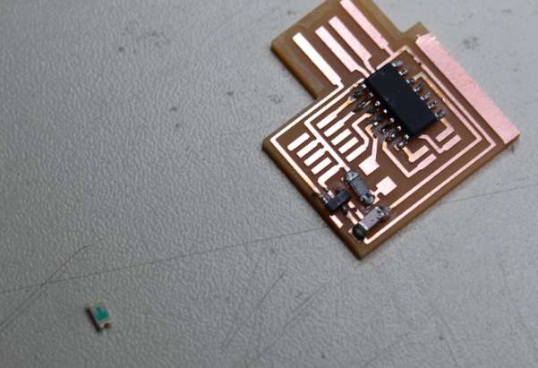
Finding components
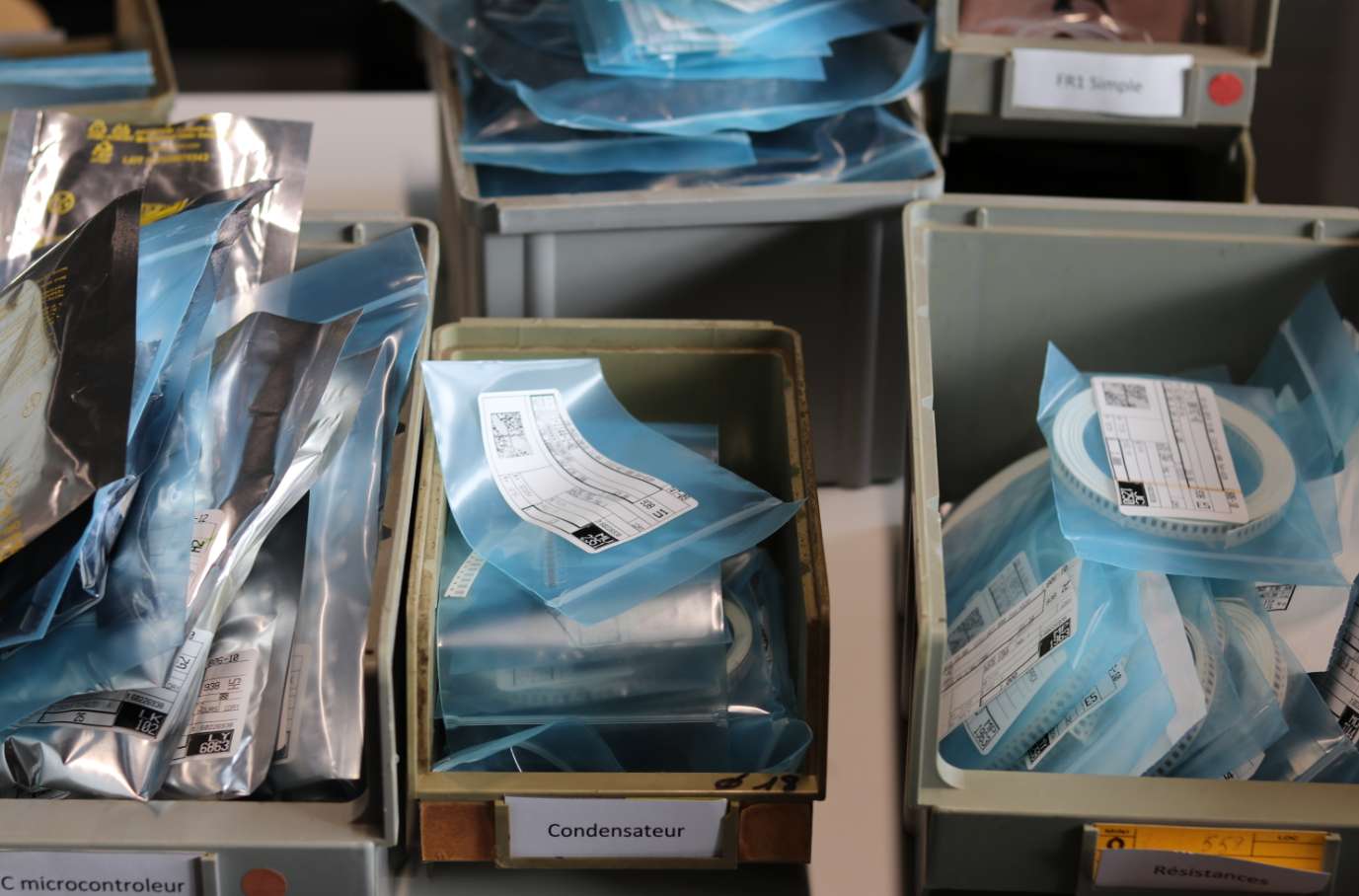
In parallel of milling, without BoM, I use (with Luc to help me) picture and design of circuit. I need 1 SAMD11C, 1 led (I chose a blue one), 1 1k resistor, 1µF capacitor and 3.3V regulator. I printed circuit design and place components to verify sizes, it seems ok. I take 10pins and 4pins connector, because there’s only one size, I don’t take time to verify on 1:1 printing, wrong…
Soldering
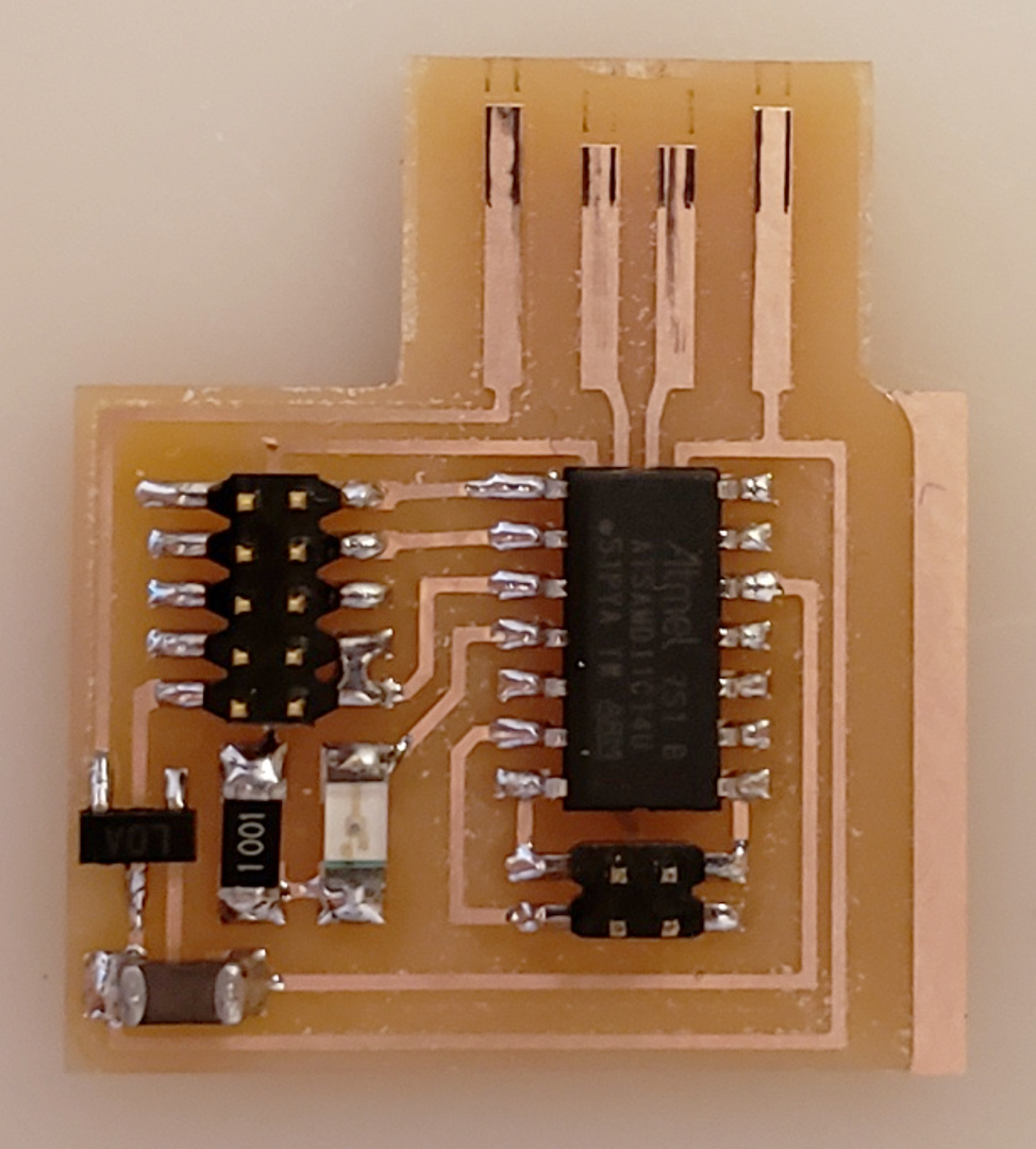
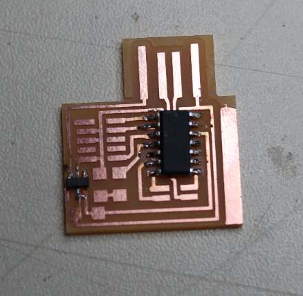
Before soldering, I verify the CNC milled circuit is the same as the design.
Time to solder all my little component on my sweet milled with love board. Hard part for me because I know I’m shaking when I need to solder, and it’s smaller than things I have soldered before.
In EU, we have to solder with lead-free tin so it’s a little bit more difficult.
I solder from hardest (that seems for me) to easiest difficulty of soldering so I start with SAMD11C.
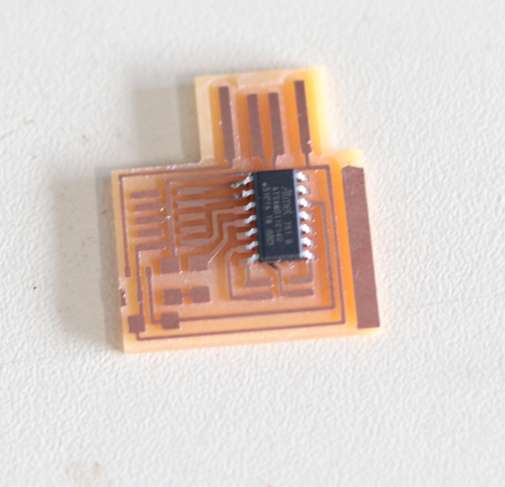
I start by soldering 1 tab, I align correctly component, now I can solder other tabs. When I verify alignment and before soldering all the first time, I’ve see I’ve made a mistake : the component was placed on a wrong copper line. With only one tab soldered, is easier to remove :) Sorry no photo of the mistake.
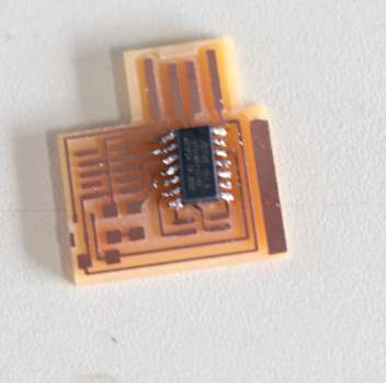
Then I place and solder the IC regulator with the same method. I put tin on circuit, I heat and place component and I solder remaining tabs. I’ve burned a little the board when heating and placing…
When soldering tabs, I made a unwanted bridge.
I remove excess of tin by heating and using desoldering pump. Then I add the resistor and the capacitor. Time to solder the LED but I have to check the orientation. I see a green point on the upper side, but the inside of the led seems to be inverted… do I chose the green point or the internal design of led? On the down side, I see a “green T”.
So I made a quick search and I see this picture :
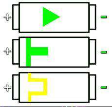
(credits : http://www.logic-sunrise.com/dossiers-et-tutoriaux-345312-changez-les-led-de-votre-xbox-slim.html)
So I check with the design and this to have correct orientation.
It’s time to add last parts : the connectors. And at this point I interiorly (or not) scream NOOOOOO. We only have 2.54mm pitch connector at AgriLabs… We have to order 1.27mm pitch connector. Go go go and pray to have it in time…
Can I finish during this week???
Edit: Last Day
I have the good connectors, 3 hours before local review, short but ok let’s do it! I solder the missing 4pin and 10pin connectors, ok. Testing ok. Time to flash…
Plug into programmer by using the 10pin connector side, no connection, many electrical testing. Adding tin to USB part, etc. Still nothing!
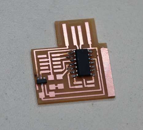
1h before local review, I discover the programmer with Luc by review design it have to be programmed by the 4 pin side… and I have to mill another PCB for 4 to 10 pin converting… Are you serious?
I use mods, I regenerate traces & interior, keeping my parameters. ok. I print at real size the board and find enough place on a little part of PCB still in the SRM 20, houra. ok. I put a 0.4 mm endmill, I set the X,Y 0. Then the Z 0 by the multimeter method. ok. Launching SRM20 with the traces. vacuum crap. ok. Changing endmill with 1mm one. Set Z 0 with multimeter method. ok. Launching SRM20 with the traces. vacuum crap. Removing the board with a screwdriver. ok. Finding 4pin and 10pin connectors. solder them. I start with the 10pin or 4pin will block me. Put tin on PCB, solder 1 pin and placing, fine. Solder others pins. Same with 4 pin connector. ok.
Rush time on PCB production passed !
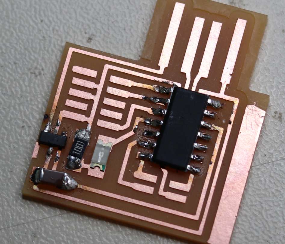
Testing PCB
For this part, I use a multimeter and use continuity mode.
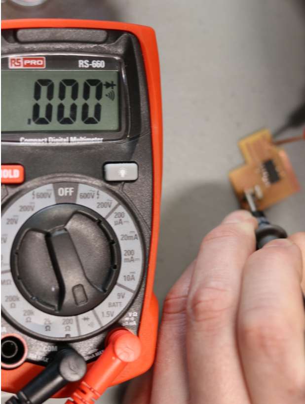
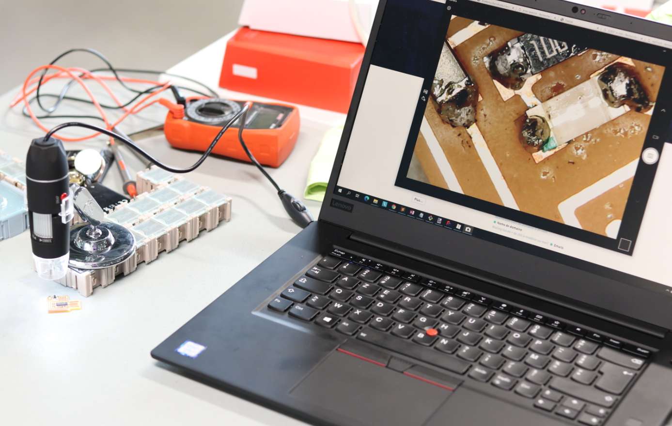
All is ok. Double checking is safer, so I try another method : USB microscope. I use a cheap ebay/chinese microscope, let’s try.
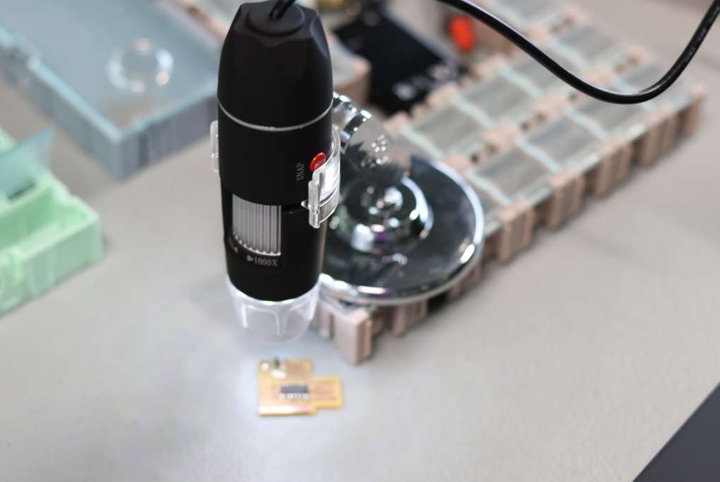
It seems correct too
Flashing
Because of lack of connector, I can’t do this part at this time.
edit: last day 20min before local review, 10 to 4 pin board ok. let’s go. Problem, no 4 pin cables. We try find one. None. I build one.
10min, green on programmer, seems ok. Flashing… failed no green light, what? Trying to invert. Back to green light. Another flash… failed
I use this command line :
edbg -b -t samd11 -pv -f free_dap_d11c_mini.bin
Time to local review…
This part is well more explained on my week 7 page, on the “Flashing & little dev” section.
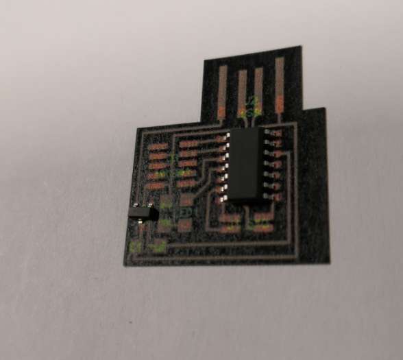
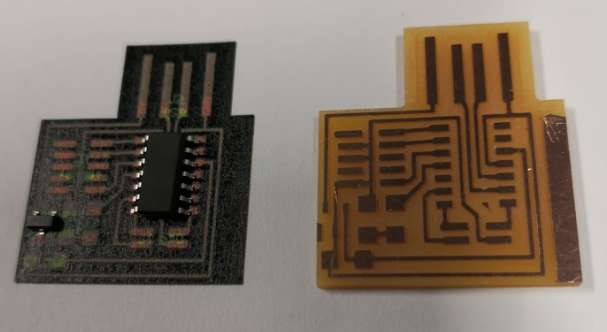
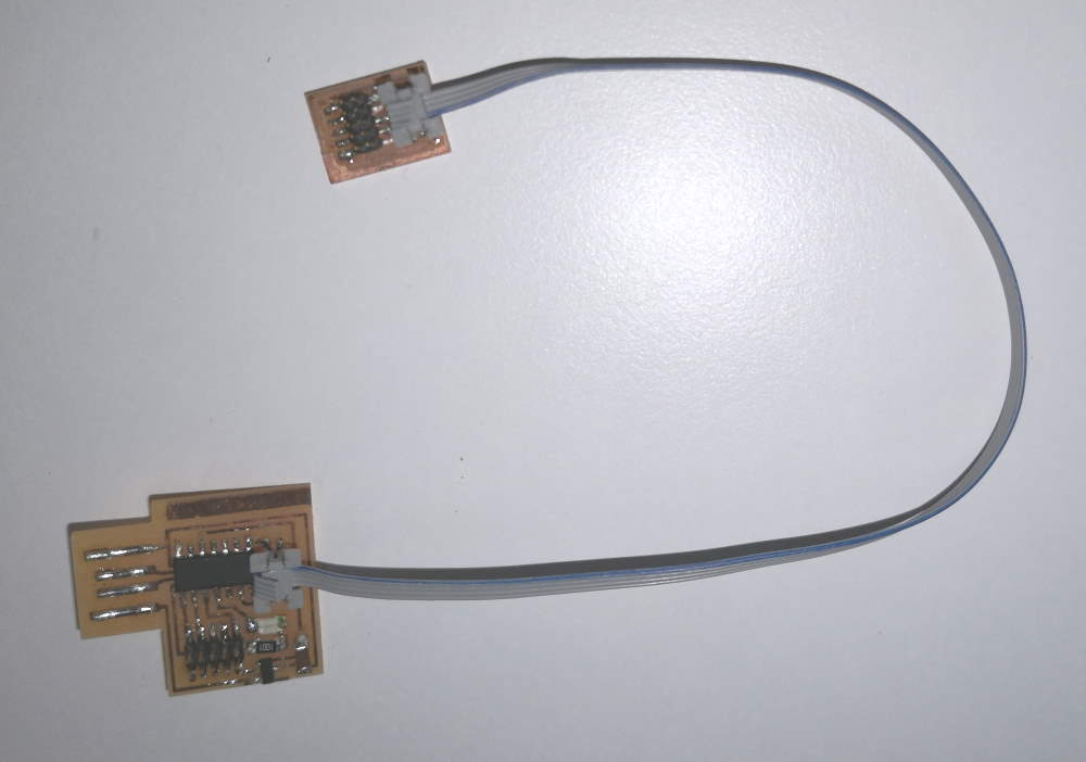
Hero shot
Here a quick hero shot of the 2 boards and the cable I made
)
)