Final Project - Step by step
Reverse engineering
Research
I’m a petrolhead so I’m always working on projects around cars, but this time I’ll make something different.
A enhanced self cleaning litter!
I’ve cats at home and 10 years ago I’ve bought a very useful object: a self cleaning litter called “Litter-Robot”.
In 10 years, I’ve changed many parts to keep it working but the controller is not reliable, I have to change it every 2 years. Finally, last year when controller die again, I change for the new version “Litter Robot Open Air”. I haven’t problem at this time but i’m not very confident…
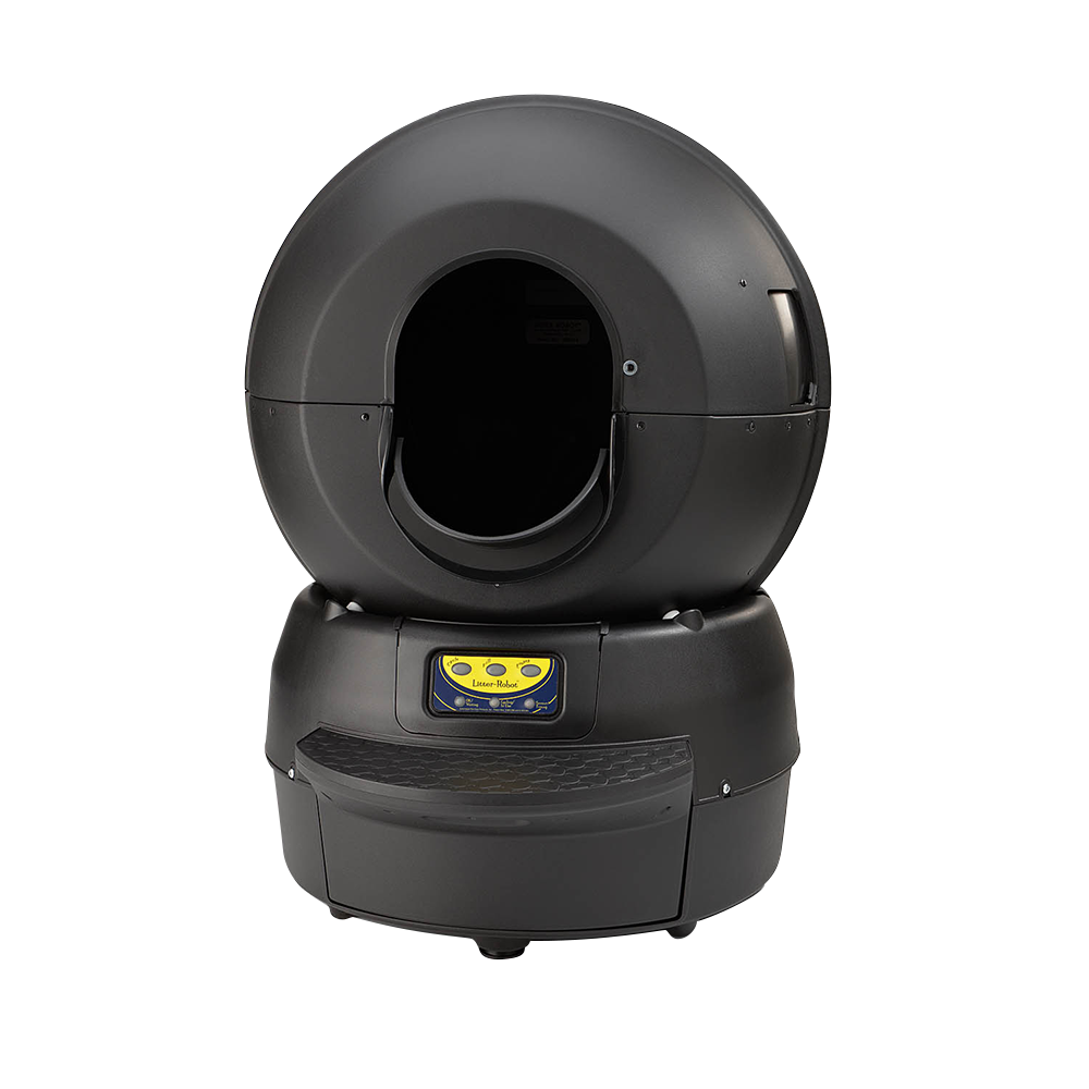
More details can be found here : https://www.litter-robot.com/the-litter-robot-ii-classic.html
A movie from youtube of how it works normally (not mine because my litter doesn’t work anymore) :
How ?
I’ve kept my old litter and try to find which component always failed but it’s a long work to reverse engineering this card so I’ve decided to make a useful project, create an open source version of this litter.
I will keep the structure and motor (I’ve changed it 2 years ago) because it’s still functional. There’s also sensor to detect cats (load sensor, anti pinch, hall effect for the rotation) I will reuse if they still work after testing.
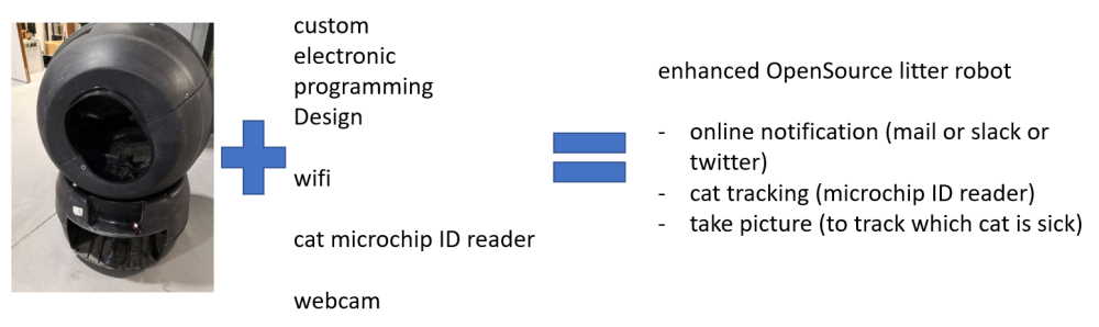
I will create a new electronic board, a new control panel and had some fun/useful stuffs like online alerting when waste drawer is full.
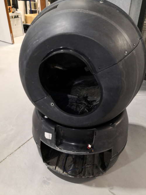
My old litter robot :
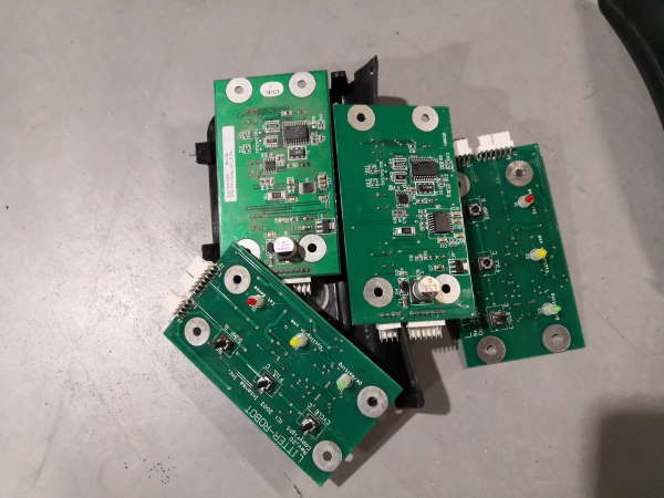
Old useless controllers :
Project diagram
The first version of my project diagram.
Reverse engineering
I made the reverse engineering by unmounting the liter, reading the user manual and finding patents.
How it works from factory?
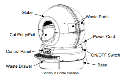
The litter have 2 main parts :
- upper part : the globe
- lower part : the base (include the control panel and dump tray)
The main function is to rotate the globe on the base : the cat enter in the litter, he does what he have to do (or not if he’s just curious ^^), after a few minute, the globe turn and come back to it’s initial position.
By rotating, litter robot separate the clean and used litter and eject used litter in the dump tray.
It’s magic? No, it’s science!
First, we have to use clumping cat litter.
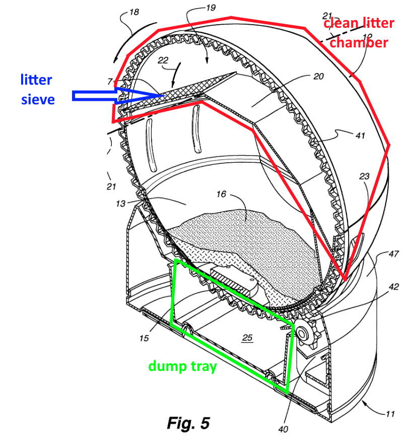
When the globe rotate CCW (counterclockwise) , all inside rotate with obviously (nooo, not the cat) and the sieve separates clean litter from waste solid. At the end of the first rotation, all the rest that not pass through sieve fall in the dump tray. Then globe rotate CW (clockwise) go back to initial position.
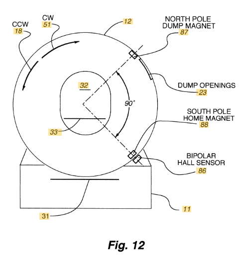
To find where is the globe, there is 2 magnets molded in the plastic of the globe. One for the dump position, one for the home position. The “bipolar hall sensor” is in fact composed of 2 hall sensor assembled together in inverted position, I assume they are plugged in digital way so one pull up when in front of the corresponding magnet (with my tests on week10, when using a hall sensor in analog, with only one I can detect both north and south pole).
The front panel contains 3 buttons and 3 LED.
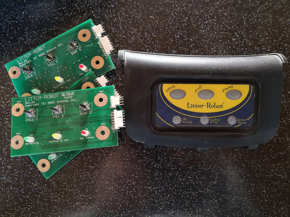
- “Cycle” Button Pressing the “Cycle” button starts the Litter-Robot cleaning cycle. To stop the cycle, press any button on the Control Panel. Press “Cycle” once again to resume the cleaning cycle. If you stopped the Globe during the cleaning cycle, pressing “Fill” or “Empty” will return the Globe to the home position.
- “Fill” Button Pressing the “Fill” button on the Control Panel starts a counter-clockwise rotation of the Globe to bring the waste ports to the top. This position is convenient for filling the Litter-Robot with litter. (Personally I never use this and add liter by the front hole)
- “Empty” Button The “Empty” cycle removes most litter from the Globe, bypassing the sifting screen. This cycle is convenient for removing the old litter prior to cleaning the interior of the Globe.
- Green Light (“OK/Waiting”) This light indicates that the unit is OK and that the Litter-Robot is ready for your cat.
- Yellow Light (“Cycling/In Use”) The Litter-Robot is cycling (Cleaning cycle, Fill cycle, or Empty cycle).
- Red Light (“Sensor/Timing”) The red light indicates that the Cat Sensor has been activated and the Litter-Robot is going through the seven minute count-down before starting the cleaning cycle. If the red light is flashing, an error has occurred, please see the Troubleshooting section for steps to take to solve this problem.
There is also a control panel lockout feature that can be activated/deactivated by pressing any button for ten seconds.
The user manual says the cat is detected by a “cat sensor”. Without unmounting, it can be a load sensor but after I see it’s a very simply and smart way. It’s a NC-NO switch activated by a spring-loaded leg
Because, it used by animals, there is also safety features :
- Cat Re-Entry Protection Mode Remember don’t turn the cat! If the Cat Sensor detects that your cat is trying to enter the Litter-Robot during a cleaning cycle the Globe will stop rotating. The Litter-Robot then waits for 15 seconds before attempting to resume the clean cycle.
- Anti-Pinch Safety Feature The Litter-Robot comes equipped with an anti-pinch feature to make the Litter-Robot extra safe for your cat. If a potential pinch condition is detected, the Globe automatically stops and then reverses direction for approximately 2 seconds.
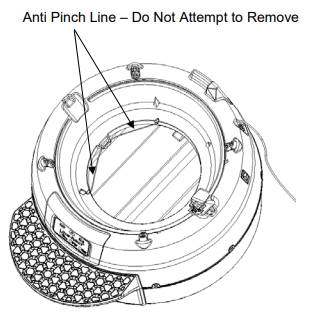
One time again, anti pinch line work is a clever way with just a NC-NO switch !
- Automatic Shut-Off If the Globe becomes jammed, the motor will stop and all three lights on the Control Panel will start blinking at a rate of twice per second.
I also have to integrate error management of the original system :
- If the Globe cannot find the home position, all three lights on the Control Panel will blink at a rate of once per second.
- If the Cat Sensor is continuously interrupted for more than two minutes the globe will remain stationary and the Red light will start flashing (may be caused by cats or excess of litter)
- If the Globe becomes jammed or if the rotation of the Globe has become obstructed or interrupted several times, the motor will stop and all three lights on the Control Panel will blink at a rate of twice per second.
What I want to change / add ?
I want to make another board and have a better lifetime of the circuit board.
I also want to add self-diagnosis functionality to check which part I have to change because local repair service just says change this, change that, etc. and you often change parts that still work and don’t resolve problem or you have to send all the base for a check but it’s expensive just for the diagnosis when warranty is expired.
I also want add some monitoring :
- how often the litter is used
- which cat & when
- detect if a cat is sick
- night mode
- online connectivity by sending notifications (at least if there is a problem, or realtime when a cat use it and maybe some fun stuff like twitter) and/or app/webpage/domotic system integration (Calaos, Domoticz, Jeedom, Home assitant, OpenHAB… I don’t have chosen yet which I will use at home) to check status.
- maybe dump tray level sensor (but it needs to open base and make holes, ok for mine but not for a retrofit kit)
Parts
On week 10 (input devices), I work deeper on sensors inside.
What I reuse (after testing) :
The base including :
- NO-NC switch of security line
- NO-NC switch of cat sensor (spring loaded leg with switch)
- I don’t know yet if I reuse the 2 hall sensors, just one of them or a new one. Because of the use of 2 inverted sensors, I think they are used in digital mode. In my testing, I see that a hall sensor can detect polarity if I use it in analog way.
- DC motor with gear assembly (already replaced 2 years ago), rated to 12V
- DC power supply (replaced 3 years ago)
- female power plug
- power button
All the upper globe :
- 2 inverted magnets inside the globe (molded inside plastic)
I want to make a retrofit kit so I try to keep as many parts as possible to avoid user to remove too much parts inside (To change the front panel is easy and don’t need tools, unmount all the base may be difficult for some people.)
New parts :
- 2.54 male pin headers for my board (for directly replug factory wires without soldering or change connectors)
- (optional) 620-1402-1-ND / SENSOR LINEAR ANALOG SOT23W (if factory ones doesn’t work as wanted)
- ATSAMD11C14A-SSUTCT-ND microcontroller because I already use it and love it !
- resistors, IC regulator
- ESP32cam
- new 3D printed front panel
- PMMA lasercutted gate (for wiring the coil for tag reader)
- FDX-B reader (it’s derived from RFID but not the same frequency)
- LED (one RGB? or many simple color LED?) and/or screen (may be a touchscreen)
- button (and/or touchscreen)
- CNC milled enclosure / cabinet in wood to hide the litter
Update : This is a first draft, go to my final project page to view final BoM.
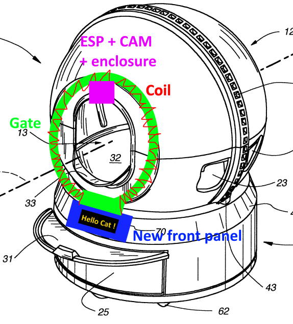
The idea in picture
What already exist? Technological watch
Obviously the litter itself ! There’s a newer version, called the Litter Robot 3 or Litter Robot Open Air, I have one at home.
The cat sensor is different and it’s now at the back instead of front… bad idea. There’s a dump tray level sensor (with infrared emitter & receiver), a light inside (off, always on or bright detector), night mode (litter don’t make cycles during 8 hours) and repeat the 8-hour period every 24h, wait time between cat detection and cycle can now be modified.
They also made a few months ago a litter robot 3 connect. It add wifi and online functionality like IOS/Android app with notifications, statistics and some settings. It also have compliant with IFTTT.
No retrofit kit exists for the litter robot 2.
Connect functions are good but it works only if you have one cat. If you have many cats, you can’t know which cat goes in.
Cat need to be identified by tatoo or tag. Tags reader are used by veterinary to check the pet. It’s also can be use by pet door or pet feeder. Why not use same system on a litter?
With the cam, you can also check the cat poop and see if a cat is sick.
Standard for pet tag is FDX-B.
3D scan
On week 06 (3d scan & printing), I’ve worked on 3D scan, I need to modify the front panel of the litter to replace electronic.
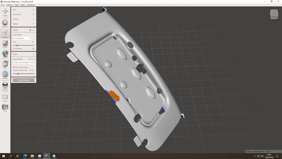
Here a scan of the inner side of the front panel in week 06.
After the first time, I think I have to scan the outer side and mix all in a 3D software but with COVID-19 and the shutdown, I take 3D scanner back to home. I spend time to improve scan technique. In week 06, I’ve already see that the structured light scanner (Einscan pro+) work better with clear color surfaces, so I use talk powder on my black object to improve scan. After many hours of testing, I finally got a good result.
On the software, I scan in various position, I add some DIY support (here a back box or clothespins) to change point of view. The einscan software can mix sub 3d scan in a global scan (automatically when there are enough details and enough superposition between scans, of I can also set it manually by placing reference points between sub scan when it failed) and at the end reconstruct all the object.
I don’t know why (surely false positive on 3d scan software) but I have holes in my model. So I use meshmixer to repair the object. I think in some scans, the software think I have put reference points on physical object.
These 3d model will be a base for my custom cover, I don’t have to lost time to rebuild shape that surrounding the base of litter, I will remove button and led parts and modify to add enclosure for my project.
I clean mesh and filling holes with meshlab.
During COVID19 shutdown, I take time to improve my 3D scan technique.
Here my scan workbench at home with the Einscan 3D pro plus (discover 3 3D scan techniques on my week 06)

To be able to scan my object, I use talc powder. I improve process by using (not shown here) paintbrush to apply the powder (it improves very well the scan quality because powder is better applied than just sprinkle the object) and a glove to manipulate object because fingers leave traces on object.

I also use clothespin to help in scanning the object in various angle.

I scan object in many passes, here is the result on one pass

And here the global result

Later (with the full improved object preparation), I also take habit to remove all green points on each pass because at the end, these points are converted to holes, very strange behavior. Here on my second run, I export and try to repair with meshlab & meshmixer but it’s a very very long process. That’s why for my 3rd and latest run, I spend more time of the scan process itself to have a better result and avoid all mesh rework!
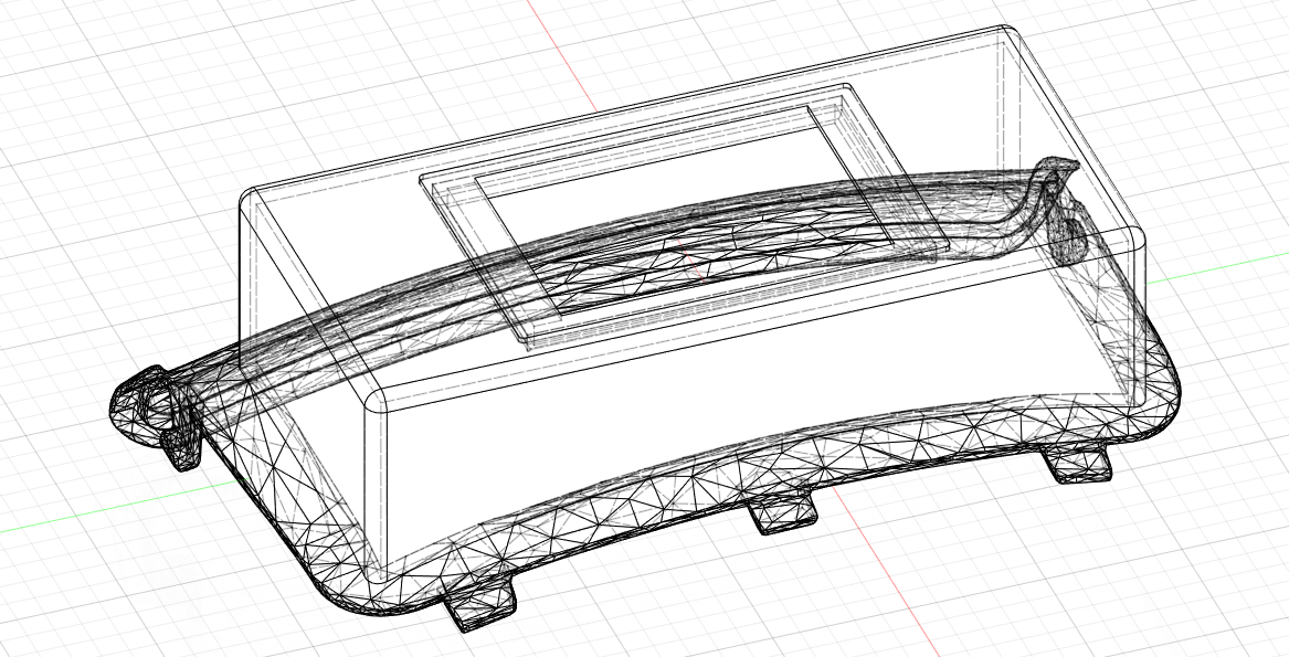
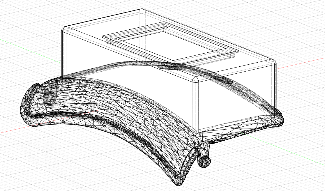
I reduced mesh in fusion360
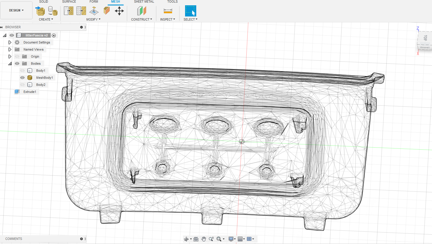
Then I add my own design, I start to cut and add a housing for my electronic. Because I’m in 1st round of my spiral, I keep many spaces.
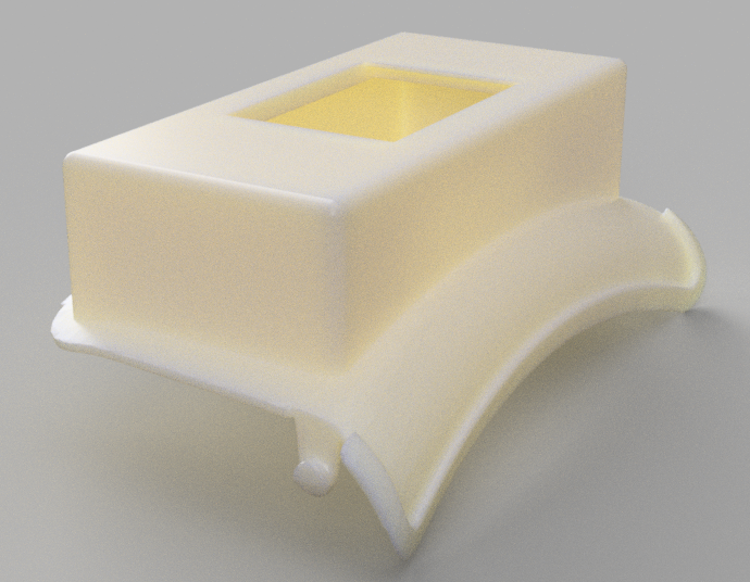
A beautiful render in white ABS.
Generating Gcode in Cura.
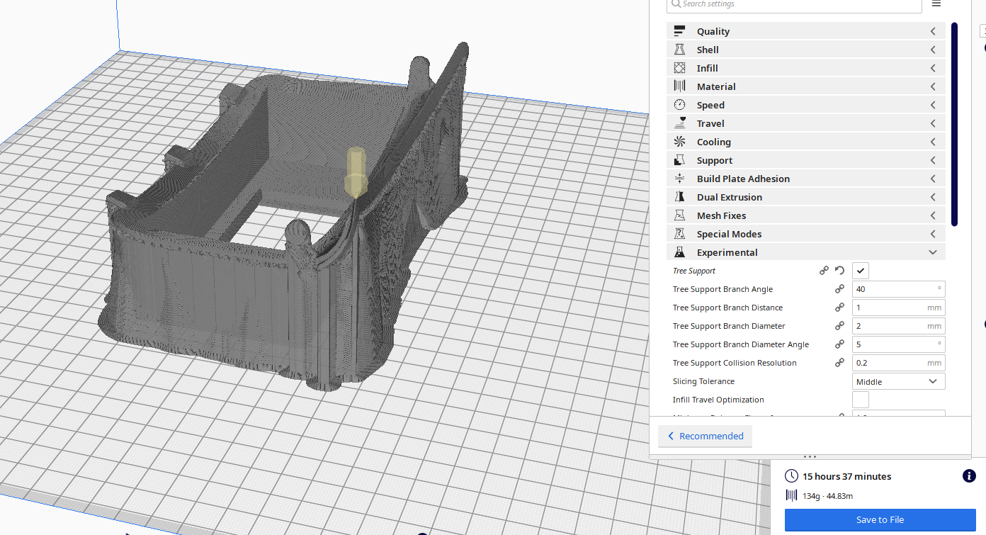
Because printer is already busy, I print it at home on a Creality Ender 5 Plus.

And the result with all mounted :

testing SAMD
multipurposeSAMD11C
I draw my own multi purpose SAMD11C board for testing
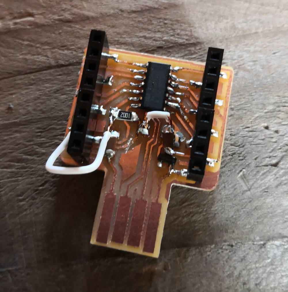
Here’s it’s the first version, when wiring I’ve found error on paths, because of coronavirus I can’t mill new board with corrected paths so I correct manually on board.
Because all pins are wired and I have squeezed pins dedicated to first flash bootloader (after USB is used to flash program), I’ve made my own cable to flash the SAMD11C microcontroller.
multipurposeSAMD21E
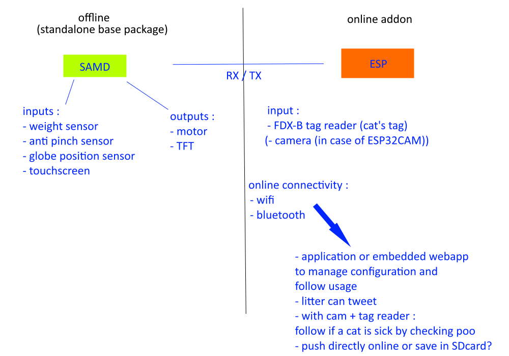
Because SAMD11C I use on several weeks can’t manage a ILI9341 due to lack of memory, I decided to switch to a SAMD21E to do this.
I can simplify the work if I delegate the TFT management to an ESP32 or 8266 but I want to make 2 different versions in the future (one online & one offline, it will increase the cost of the offline version). I keep this possibility as a shortcut if I get stuck with the SAMD21E.
Here the global idea :
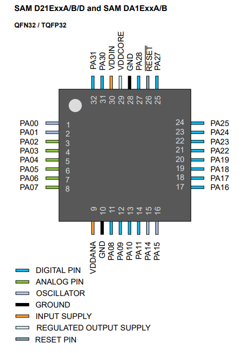
I go to fabacademy components list to check which version of SAMD21, it’s the ATSAMD11D14A-SSUT

It’s available at digikey here.
The datasheet is available here. I found the following pinout on it :
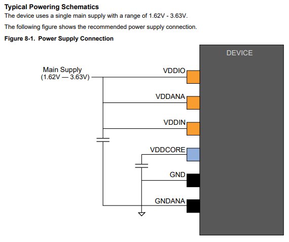
How to power the chip:
To design my board, I have to find the correct symbol & footprint, there are available here : https://www.snapeda.com/parts/ATSAMD21E17A-AUT/Microchip/view-part/?ref=digikey because the SAMD21 is the wrong one on fab library.
To power my chip, I choose this in fab list :

With 1A, I’m sure I can plug many things when testing, by example the TFT with backlight may be drain lot of power.
Flashing the board with edbg using the SAMD21 bootloader from mattairtech available here.
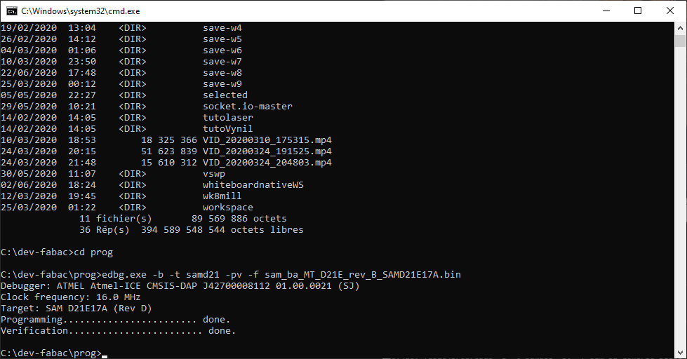
A little test to verify board is correctly up and works with arduino :
void setup() {
Serial.println("HelloWorld!");
}
void loop() {
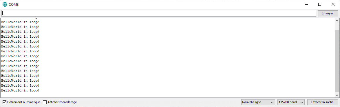
Serial.println("HelloWorld in loop!");
delay(200);
}
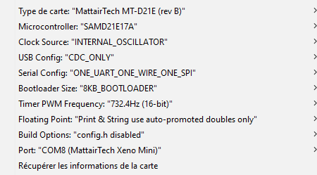
And my arduino settings :
Quick test success in serial monitor :
I want to reuse a library I already use with ESP8266 TFT_eSPI, infortunately, I can use it on SAMD11C because of memory size (I had to write a full custom library to use a Nokia5110 screen instead) so I want another try.
I first try basically with these settings in the library :
//SAMD21
#define TFT_CS   14  // Chip select control pin D8
#define TFT_DC   8  // Data Command control pin
#define TFT_RST  15  // Reset pin (could connect to NodeMCU RST, see next line)
#define TFT_MISO 10
#define TFT_MOSI 9
#define TFT_SCLK 11

#define TOUCH_CS 16
I’m thinking maybe soft SPI works here but finally i still have a blank screen and no touch response so I search from mattairtech the PIN functions (like the last time for the SAMD11C) and you find more informations here :
========================== MattairTech MT-D21E rev B (ATSAMx21Exxx) =====================
Other  COM    PWM   Analog  INT  Arduino*             Arduino*  INT   PWM     COM   Other
=========================================================================================
                                      -------------------
XI32(+)                              | A0            RST |                        BOOT(+)
XO32(+)                              | A1            Gnd |
DAC                   *            2 | A2           Vbat |
REFA                  *            3 | A3            A31 | 31    *           RX3  IO/B(+)
REFB                  *      *     4 | A4            A30 | 30    *           TX3   CLK(+)
DAC1(L)               *      *     5 | A5            NC  |
LED(+)        TCC10   *            6 | A6       A28 (D/C)| 28    *
VM            TCC11   *            7 | A7            A27 | 27    *               A/CS(+M)
  SDA1/MISO1  TCC00   *     NMI    8 | A8            A23 | 23    * TC41/TC01~ SS
   SCL1/SS1   TCC01   *      *     9 | A9            A22 | 22    * TC40/TC00~ MISO(+M)
      TX1     TCC02   *           10 | A10           A19 | 19    *            SCK(+M)
      RX1     TCC03   *           11 | A11           A18 | 18    *            MOSI(+M)
  TX2/MOSI1 TC30/TC40~       *    14 | A14           A17 | 17    *   TCC21    SCL/RX4(+)
   RX2/SCK1 TC31/TC41~            15 | A15           A16 | 16    *   TCC20    SDA/TX4(+)
                                     | NC            NC  |
     M=Memory device installed       | NC            NC  | ! Vcc is 3.3V by default.
                                     | Vbus          3.3V|   DO NOT exceed 3.6V on Vcc or
USB D- (D/L)(+), CAN TX (C)  TC50 24 | A24   _____   Vcc |   any IO pin with the D21 or
USB D+ (D/L)(+), CAN RX (C)  TC51 25 | A25  |     |  Vin |   L21 installed. 5V is allowed
                                     | Gnd  | USB |  Gnd |   ONLY with the C21 installed.
           Chip Variant:              -------------------
        D=D21, L=L21, C=C21
So I wire for hardware SPI, the pin are :
//SAMD21
#define TFT_CS   4  // Chip select control pin D8
#define TFT_DC   2  // Data Command control pin
#define TFT_RST  3  // Reset pin (could connect to NodeMCU RST, see next line)
#define TFT_MISO 22
#define TFT_MOSI 18
#define TFT_SCLK 19

#define TOUCH_CS 5

I have a bug when using TFT_eSPI, I have my touch responding but no image on screen. I try different solutions, verify my solder, adding tin to be sure all contacts are good, testing another pins and so on.
I decide to fallback to UCGlib and my screen works, cool!

So my chip is correctly wired, my screen works but… UCGlib doesn’t handle touchscreen AND I WANT MY TOUCHSCREEN!
I go back to TFT_eSPI and finally found where is the bug. It’s due to the main problem of this library, settings are global! And because I’m tired, I modify settings on wrong library folder… my code and my wiring works from the start…
In the future, I certainly made a fork and rewrite this part because for my work at AgriLab, I use many different boards, micro-controllers, wiring, screens and having to modify configuration directly in library folder is such a pain (and a big source of misconfiguration and time loss).
Here some hero shot of using TFT_eSPI on a custom SAMD21E board, 1st a matrix effect (like my homepage ^^) :
And a touchscreen + screen test (I reuse some code of my machine week) :
So my final questions about this part are now answered, I can add my others parts for my first spiral.
Driving my motor
Because motor have to go in normal and reverse mode, relay can’t work, I need H bridge. Looking in fab lab inventory, I have 2 solutions :

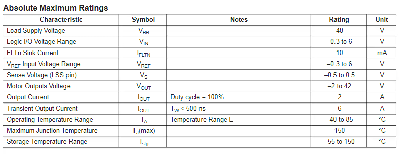
I choose the 620-1428-1-ND, here are some informations from datasheet (available here in html) :
The pinout :
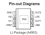
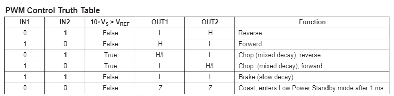
How to control it :
I create a custom dev board with his A4953 and have a way to expend my breakout boards (here my SAMD21E one)
The schematic is pretty simple (I double GND & VDC) because I plug power on this board and I replug my SAMD board on it
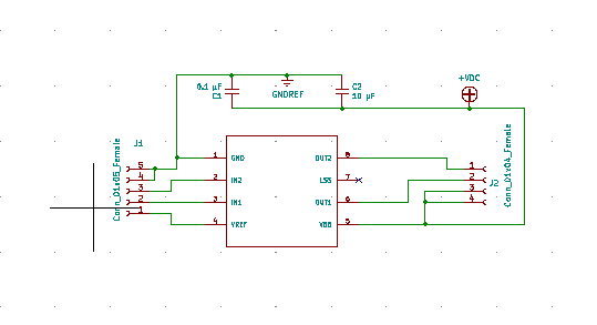
And the PCB
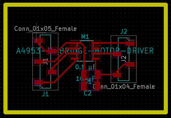
Here the board milled, soldered and plugged to my SAMD21 board:
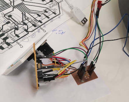
I start my test and nothing happen, I verify my solder, I verify power supply, no problem…
The problem is the LSS pin, because reading this
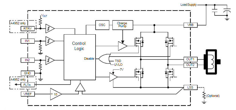
I think LSS was optional (look on bottom right on the picture)… error. You MUST put LSS to GND (only resistor is optional…) So I finally add directly a resistor between LSS & GND on my circuit and all work fine!
Using the factory hall effect sensor
By doing reverse engineering and testing, I find the 2 hall sensor in the litter are unipolar sensor. I doesn’t know exactly what version is. With the “A” letter on it, I think it’s from Allegro.
By viewing different datasheet of Allegro 3 pin hall sensor, I found (here is from the A1369 datasheet) this wiring:
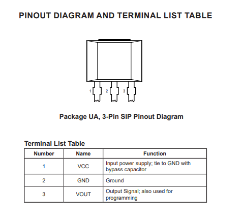
I know now the color code of the 7pin connector :
black : common GND (wired to the 2 sensors) orange : sensor 1 output signal yellow : sensor 2 output signal red : sensor 1 VCC violet : sensor 2 VCC
After many testing, different wiring, the best result is enabling INPUT_PULLUP on the PIN of the SAMD21.
I test first on a analog pin to test behavior (value are encoded from 0 to 1023).
The 2 sensor haven’t the same calibration, one give me a minus value at around 10 where the other give around 300. High value are quite the same for the both, around 900.
I can use them in digital if my LOW value is lower than 612, it’s the case. I test then in digital reading and it works as expected.
So I will work like the original board with the 2 unipolar hall sensors.
Using cat entry & anti pinch sensor
I lost so many times because manual is false on that part… Its normally 2 different sensor and functionality and… finally, after this 2 switches are… wired together in serial !!! Why? It’s totally stupid and it’s a big problem because it’s impossible to make the difference between a cat that is in the litter and a cat stuck under the globe!!!
I didn’t find this big problem on my first testing because I test directly with multimeter on 2 switches, I assume the 2 switches are grounded and have each the other wire on connector… big mistake! On the connector, the 2 wires are one for input and the other for output (of the 2 because there in serial), I choose to put ground on input and detect if circuit is low or high using pullup resistor on the SAMD, easy… when wiring is good!
edit: a few weeks later, with more sleep, I think of another wiring that can resolve that problem. Invert some wires & change code can deal with it.
Making the litter cabinet
Go to my CNC week and see the “make it big” object to see work on the cabinet with secret tenon fingers.
How the code works?
Here I will explain how my code works. It will not be available to download unlike all others parts of my work during fabacademy.
Using TFT screen and touchscreen was a big challenge, the only one method is checking in a loop if somebody touch it.
uint16_t x = 0, y = 0;
boolean pressed = tft.getTouch(&x, &y);
Another thing is my 2 sensors (cat entry & anti pinch), at the beginning I wired them with interrupt and behavior are very special and sometimes unpredictable. Also when I tested by simulating with dupont cable and touch/remove the input, I saw that electronic is far more sensible than me. By example when I think I have touched 1 time, in the same time SAMD see many touches and fire the interrupt bloc code many times (and an interrupt can interrupt a previous interrupt…) so at the end I have many micro launches (at different states because even if my bloc code if short, the micro contact is even shorter than the time used to do the code). I finally decide to check my 2 inputs like I have to check input from touchscreen in a loop. Because I need very short loops even if I do long jobs (I take more than 3 minutes to make a full cycle) because I can’t ignore some inputs (security inputs are the most important, it’s the reason why I first decide to use interrupt to manage them)
On a computer, I just have to use threads, easy. On a µC, I have only one thread, I need to simulate threads !
How? By splitting all my work and make my own job scheduler.
To answer to that problem, I decide to make my own state machine.
enum mode:byte {_CYCLE, _IDLE, _ERRORpinch, _STATS, _WAITING, _ERRORpos};
mode inMode = _IDLE;
mode prevMode = _CYCLE;
I have the 2 standard methods of arduino development : setup() & loop().
My setup is very classical :
void setup() {
  Serial.begin(115000);

  tft.init();
  tft.setRotation(1);

  //add enterDetection (+ pinch, they are wired SERIAL, WTF!)
  pinMode(ENTERPIN,INPUT_PULLUP);
  //attachInterrupt(ENTERPIN, resetCounter, HIGH); switch to test in a loop instead of interrupt

  pinMode(HALL1PIN,INPUT_PULLUP);
  pinMode(HALL2PIN,INPUT_PULLUP);

  pinMode(DCPIN1, OUTPUT);
  pinMode(DCPIN2, OUTPUT);
}
I have many methods, most of them are used to draw on tft, here an example :
void drawIdle() {
  if (inMode != prevMode) {
    tft.fillScreen(TFT_BLACK);
    prevMode = inMode;
    tft.setTextColor(TFT_WHITE, TFT_BLUE);
    tft.fillRect(0,0,320,20, TFT_BLUE);
    tft.drawCentreString(" Litter Robot EVO ",160,0,2);

    tft.setTextColor(TFT_WHITE);
    tft.fillRoundRect(0, 100, 100, 120, 3, TFT_PURPLE);
    tft.drawCentreString(" CYCLE ",50,150,4);

    tft.fillRoundRect(120, 100, 100, 120, 3, TFT_DARKGREY);
    tft.drawCentreString(" STATS ",170,150,4);
  }
  delay(333);
}
And also some utility methods like this to switch between modes
void gotoMode(mode mod) {
  prevMode = inMode;
  inMode = mod;
  Serial.print("GTM in: ");
  Serial.print(inMode);
  Serial.print(" prev : ");
  Serial.println(prevMode);
}
Or this for the motor
// moveMotor
void moveMotor(bool forward) {
  digitalWrite(DCPIN1, forward?HIGH:LOW);
  digitalWrite(DCPIN2, forward?LOW:HIGH);
  turnDirection = forward?CW:CCW;
}

void stopMotor() {
  digitalWrite(DCPIN1, LOW);
  digitalWrite(DCPIN2, LOW);
}
If you have looked carefully previous code you have seen :
- I have declared 2 global variables about “modes”, inMode & prevMode
- I check in method if they are different or not to do something
Why? Because my loop is the job scheduler. Here an extract of the beginning of my loop.
void loop() {
  uint16_t x = 0, y = 0;
  boolean pressed = tft.getTouch(&x, &y);
  //drawDebug();
  if (digitalRead(ENTERPIN)) {
    //if 1, circuit is cut so a cat is in
    resetCounter();
  }
  if (pressed)
    {
      Serial.print("x,y = ");
      Serial.print(x);
      Serial.print(",");
      Serial.println(y);
    }
I always check if I have an input before all.
To reduce false events, I added at the end of loop a little 200ms delay, with that I consider I check events at 5Hz frequency.
delay(200);
And inside my loop, after testing all inputs (my security sensors directly fire methods on top of loop), I always check where I am & what method I should fire in that case. Here by example when I am in one of my error modes :
 switch(inMode) {
    case _ERRORpinch :
      drawErrorScreen(blinkScreen, true);
      blinkScreen = !blinkScreen;
      if (pressed && y > 175 && x < 245 && x > 115) {
        gotoMode(_IDLE);
      }
      break;
If you have followed until here, you will see I can blink my screen at 5Hz.
Refresh the screen was also a big part, I can’t always refresh full screen and don’t care about it like a computer, refresh rate is too slow and you see it.
By example when I launch a method for the first time after switching to a mode, I redraw everything to avoid artifacts, but after that most of the time, I only redraw subsets of the screen (of nothing if I can). I can do that because I have states.
Here the launched method by the above case :
void drawErrorScreen(byte col, byte secu) {
  if (inMode != prevMode) {
    tft.fillScreen(TFT_BLACK);
    tft.fillRoundRect(100, 180, 120, 60, 3, TFT_DARKGREEN);
    tft.setTextColor(TFT_WHITE);
    tft.drawCentreString(" Fix the problem then press reset ",160,155,2);
    tft.drawCentreString(" Reset ",160,200,4);
    prevMode = inMode;
  }

  if (col) {
    //tft.fillScreen(TFT_RED);
    //tft.fillRect(0,0,320,20, TFT_BLUE);
    tft.setTextColor(TFT_WHITE, TFT_BLUE);
    tft.drawCentreString(" Litter Robot EVO ",160,0,2);

    tft.setTextColor(TFT_WHITE, TFT_RED);
    tft.drawCentreString(" ERROR ", 160, 60, 4);
    if (secu)
      tft.drawCentreString(" SECURITY SENSOR ", 160, 100, 4);
    else
      tft.drawCentreString(" GLOBE POSITION ", 160, 100, 4);

  } else {
    //tft.fillScreen(TFT_BLUE);
    //tft.fillRect(0,0,320,20, TFT_RED);
    tft.setTextColor(TFT_WHITE, TFT_RED);
    tft.drawCentreString(" Litter Robot EVO ",160,0,2);

    tft.setTextColor(TFT_WHITE, TFT_BLUE);
    tft.drawCentreString(" ERROR ", 160, 60, 4);
    if (secu)
      tft.drawCentreString(" SECURITY SENSOR ", 160, 100, 4);
    else
      tft.drawCentreString(" GLOBE POSITION ", 160, 100, 4);
  }
  col != col;
  delay(200);
}
You can see here, I blink 2 parts of the screen without refresh everything.
For next spirals
FDX-B reader
I’ve made many research about reading ID chips inside my cats. ISO 11784 and ISO 11785 are international standards that regulate the radio-frequency identification (RFID) of animals. You can find informations at https://www.icar.org/.
To resume it’s like RFID but the frequency it’s 134.2khz VS 125khz for most classical RFID chip & reader.
After many researches , I found a FDX-B reader. There are 3-4 designs sold but this one is supposed to have the best range. I’ve bought one from aliexpress with an antenna. It’s not very cheap (~35€). It work in serial with 2 wires.
I have made many tests on all my cats and range is only 5cm, it need some tuning to improve this.