Multi purpose SAMD11C board
For testing I/O, I create a SAMD11C multi purpose board like an arduino.
V1
I’ve started to work on week 10 on a multi purpose board I can use to rapid prototyping.
Due to COVID-19, I can’t mill the board myself because I haven’t the Rolland SRM20 at home. So Luc mill a few and send me them with the component I need. I takes nearly 2 weeks because of postal service that decided to slow down in the same time.
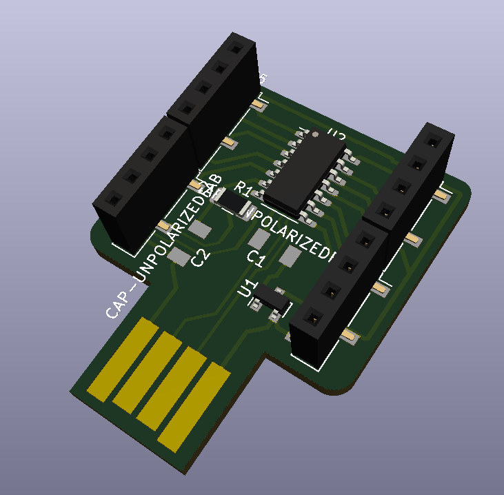
I add femelle 2.54 header because I want that board can be used with Dupont cables like an Arduino.
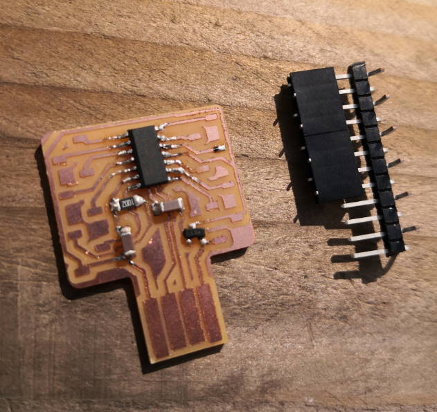
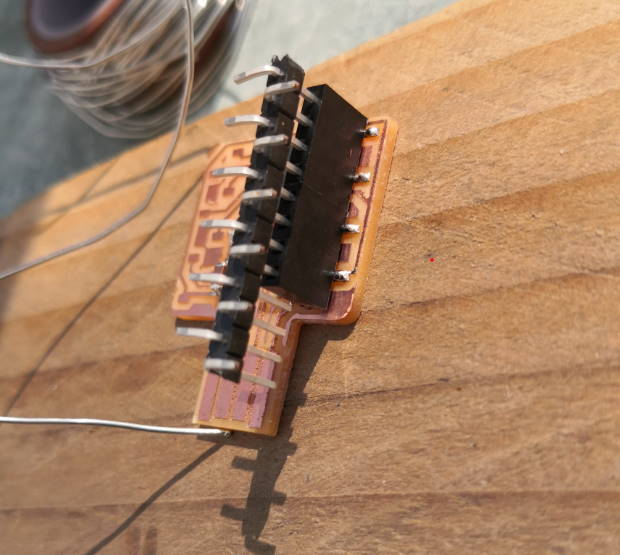
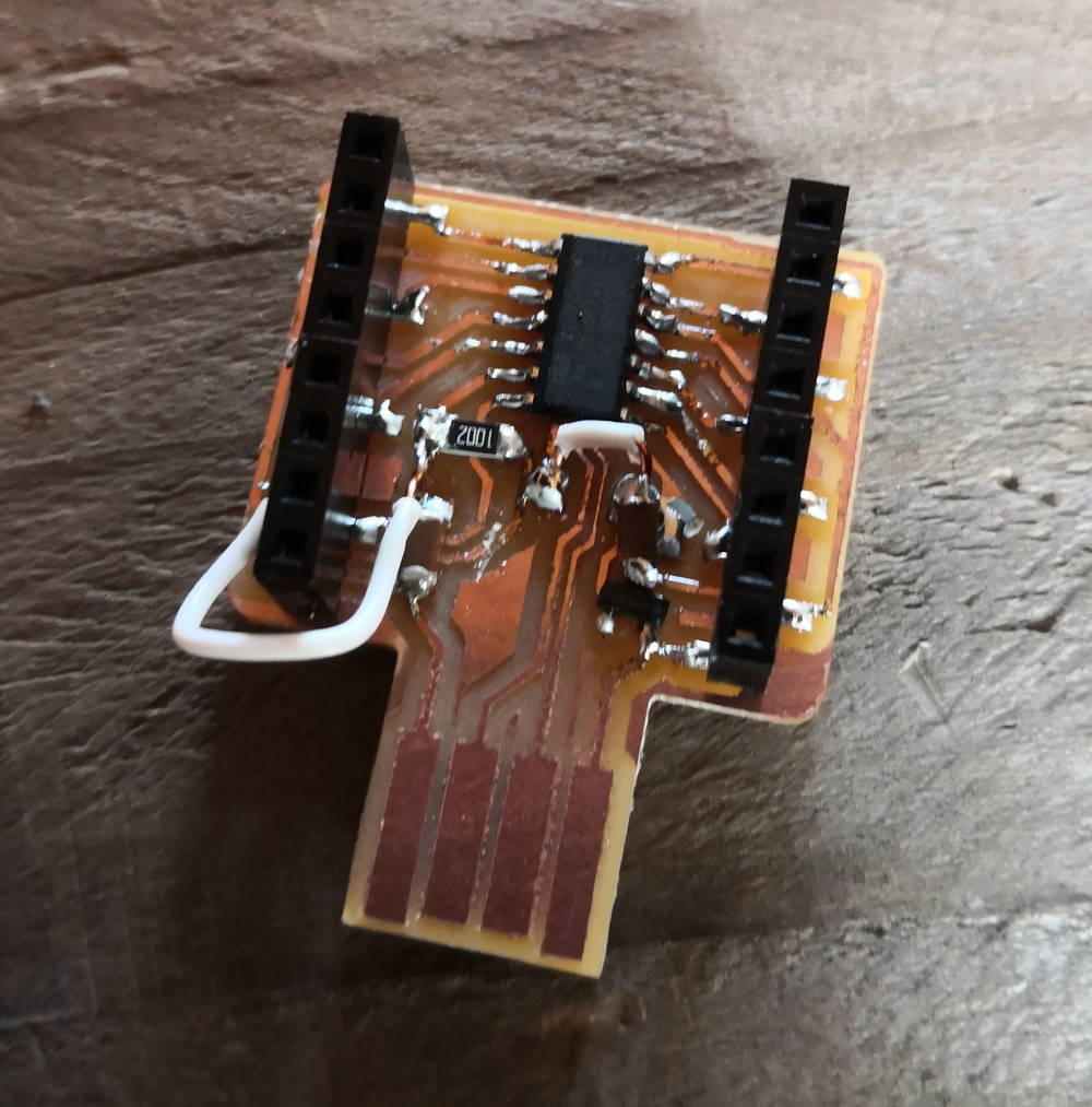
I’ve made a little mistake when mixing all boards, so when I received my board, I solder everything and when I check to made my custom cable, I found small errors. Because I haven’t the Roland SRM20 at home to mill the board, I made quick fix by cutting/wiring moving component directly on board. To correctly align my female headers in row, I plug a row of male pins and solder.
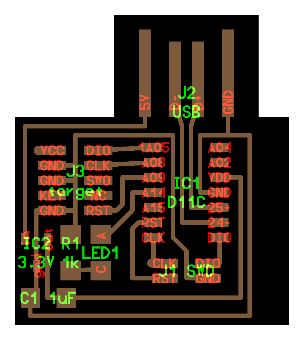
When I design this board, I want to make it as little and as cheap as possible. Because it can programmed by USB port after putting bootloader on he SAMD11C and I’ve already wired all the pin of the microcontroller, I have to make a custom flash cable.
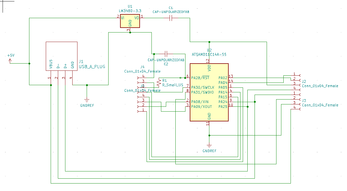
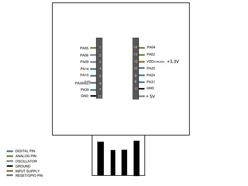
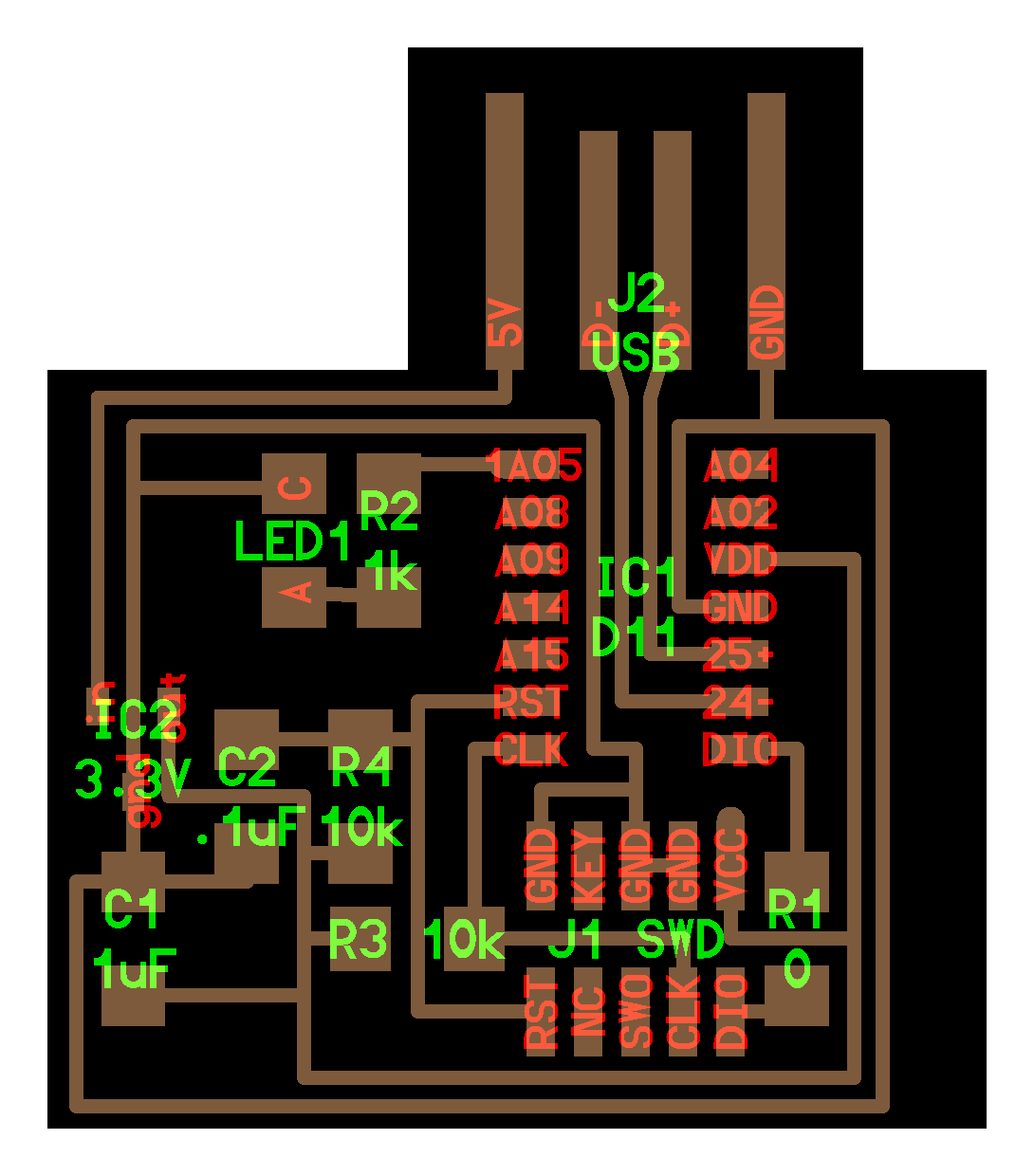
The wiring sheet of my board :
The custom flash cable
The design my board and the idea of the cable is a mix of several boards seen during the fabacademy.
This board for the idea of using 4 pins to flash the bootloader. This board for using resistors and capacitors for reset & clock. This board for the wiring of the custom cable that only need 4 pins on the flashed board.
So I finally need to wire RST, CLK, DIO & GND. The 3 GND on the 10pin connector need to be wired together. Now I need to find the pinout, I find this in the Atmel ICE user manual
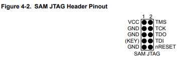
But on the original cable, there is a connector key but here I don’t know on which side!
I finally found this information here.
And now I building the cable. I have to build this cable because SWD 10pin > 2x2 2.54mm male connector doesn’t exist.
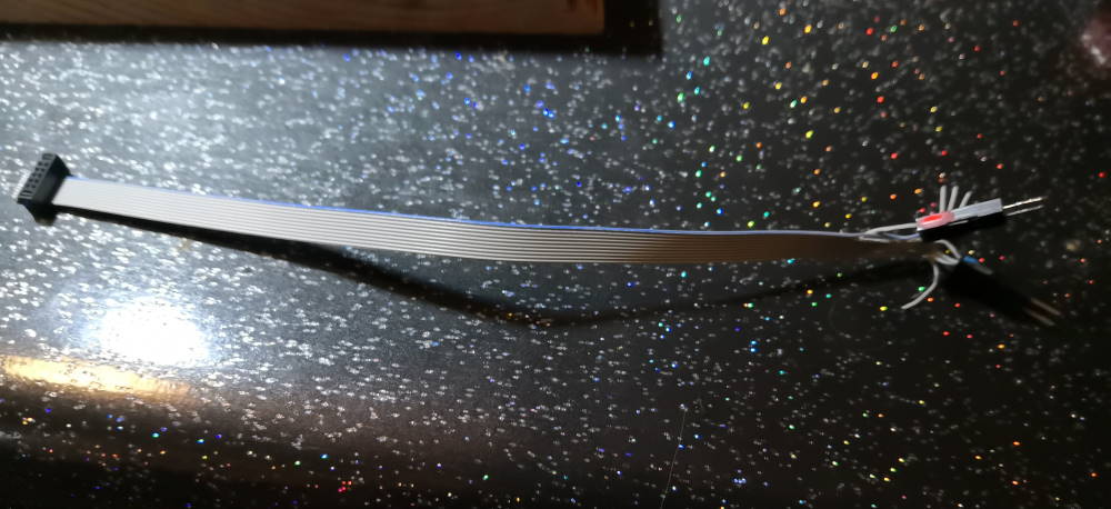
I add colors to plug correctly, when USB connector is facing me, red on left, blue on right.
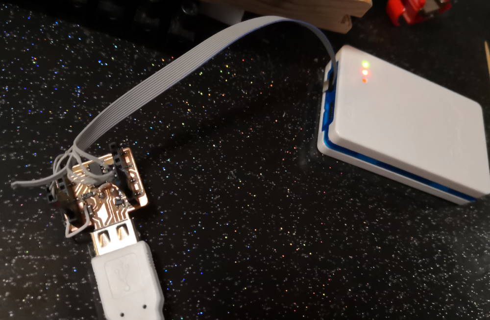
Uploading the bootloader :
C:\dev-fabac\prog>edbg.exe -b -t samd11 -pv -f sam_ba_Generic_D11C14A_SAMD11C14A.bin
Debugger: ATMEL Atmel-ICE CMSIS-DAP J42700008112 01.00.0021 (SJ)
Clock frequency: 16.0 MHz
Target: SAM D11C14A (Rev B)
Programming................... done.
Verification................... done.
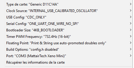
Now I can directly use the USB port and upload code directly in Arduino IDE with these settings :
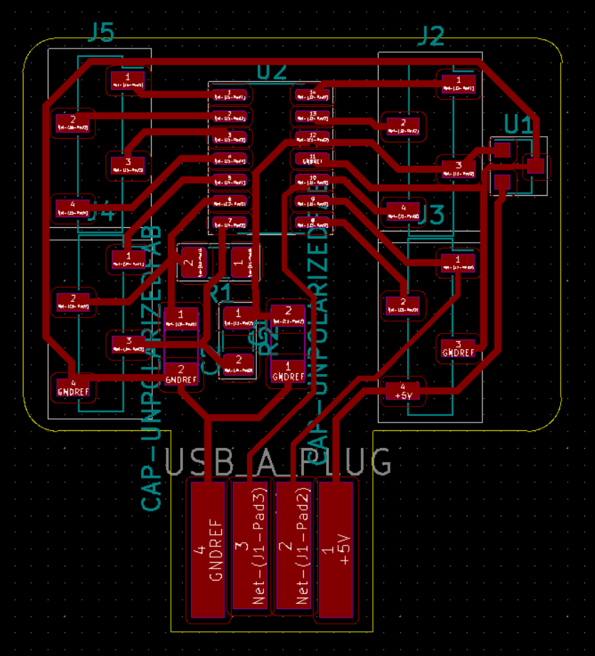
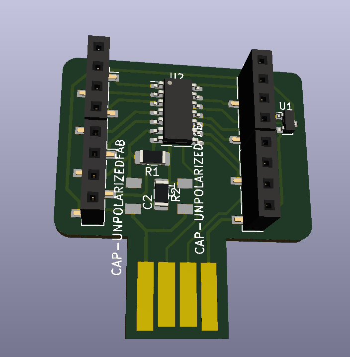
V2
Then I work on a V2, I want to avoid 0 Ohm resistor, I’m sure I can make a tiny board like this without. I spend many times on routing and finally… I’ve done it!
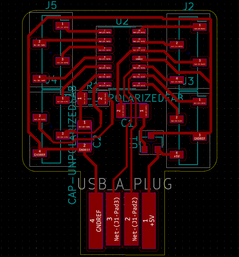
I use 0.4 and 0.3 mm track width to keep the board easy to mill.
Attachments
kicad files + SVG export : AgriLabUno.zip (I call it AgriLabUno because I design a breakout board like Arduino Uno and this board can be used for several project at AgriLab)