8. Computer controlled machining
 group assignment
      test runout, alignment, speeds, feeds, and toolpaths for your machine
   individual assignment
      make (design+mill+assemble) something big
Group assignment
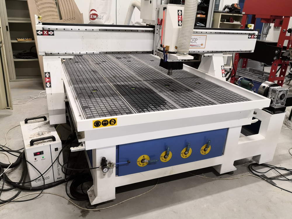
At AgriLab, we have a big CNC Working area : 2,5m * 1,5m plus a 2,0m rotational axis, cooler for the spindle motor, vacuum table.
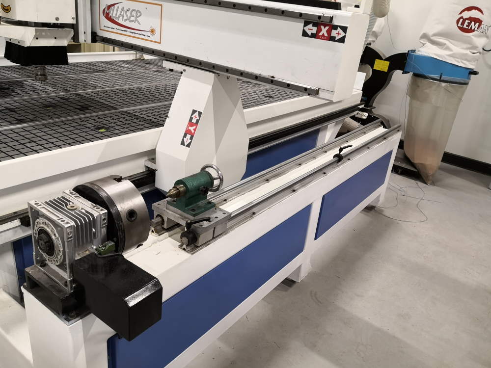
The 2,0m rotational axis and dust vacuum and collecting system.
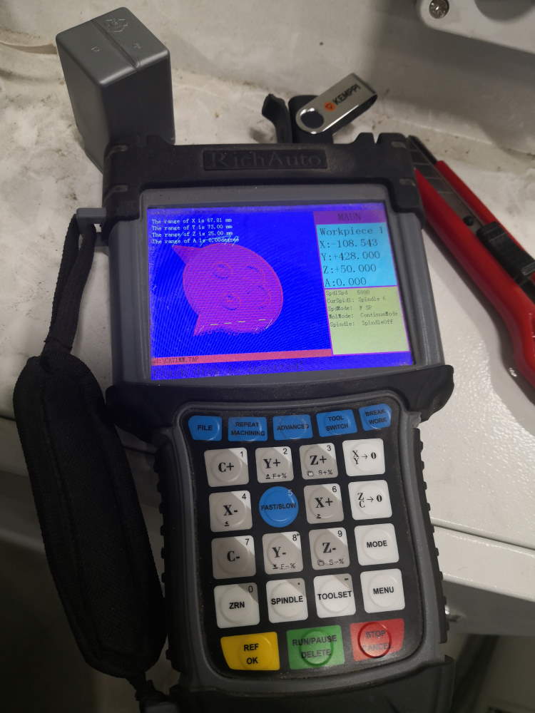
The remote control, work is loaded from USB stick.
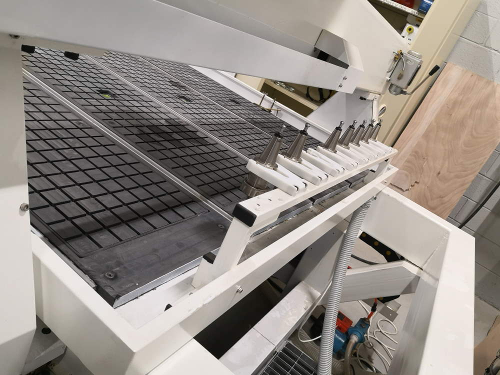
This CNC have also a 8 tools changer, but it use space on bed, so the real length of working area is more 240cm than 250cm!
I made my tests in the same time I prepare my work, I also made tests during casting & molding week (I inverted practice parts between the 2 weeks).
Here some example, more details below.
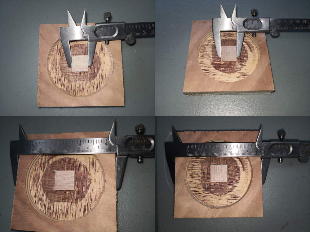
Here a test of machine resolution, I design a square in a circle in a square, we can see here different measures:
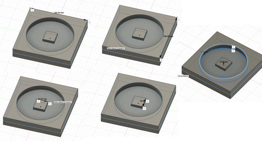
I define a box, 2cm wider than object on X&Y, 18mm in Z (my wood plank is exactly at 17.8)
I use a 4mm 2 flutes flat endmill. For the inside, I use a 2D pocket, 3mm Z step.
For the outside, I use 2D contour, 3mm Z step.
And the result IRL, X&Y axis are very accurate, I’m exactly on the specified size, even with 0.1mm measure!! :
On Z, it’s less precise but there are many reasons for that :
- I take habit to lower a little bit the Z axis to be sure my material is fully milled when cutting
- Plank may be not fully plane
- As we can see, I test in plywood, and layers doesn’t seem perfectly flat, also the resistance of wood fiber on milling. Test will be more accurate with homogeneous material like wax or MDF.
How I found speeds? I start with safe sample values given by the Luc, the Local intructor and I modify values during my testing. It’s hard to explain in a few lines because I use the same method when I work since many years with others tools. It’s a mix of listening the sound of the machine (like I can know if somebody at the other side of the fablab is using the wrong endmill on the drill), viewing the chips made by the endmill on the material, smelling the odor (if it smells burn and if you’re not using lasercutting machine, you’re problably at wrong speeds!).
My values aren’t perfect and depends on too many settings, I won’t use these values if I want to find maximum speed, I will go until machine limits or when endmill will break and slow down a little to keep security range.
Here I want to succeed and don’t break endmill (no backup endmill when I do this) so I push a little to have a good mix between result / time / don’t break anything.
Finding correct toolpaths for my case are explained below on this page when I test pressfit with secret tenon fingers for my cabinet.
Preparing the work (Fusion 360)
I start by quickly design an object in Fusion 360.
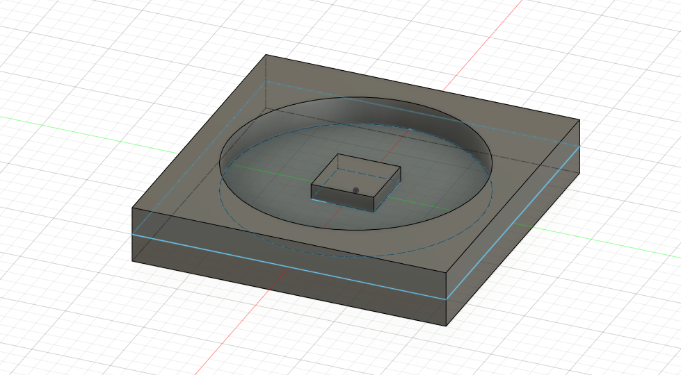
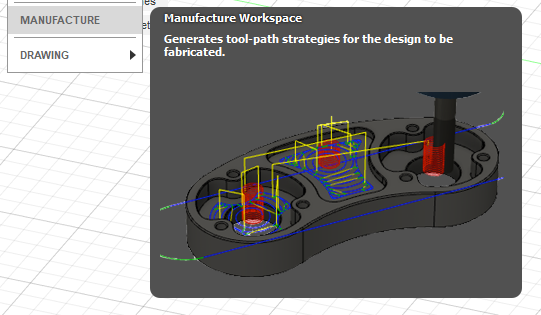
For milling, I have to go in manufacture workspace
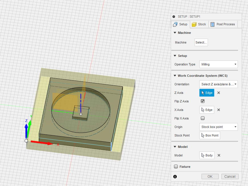
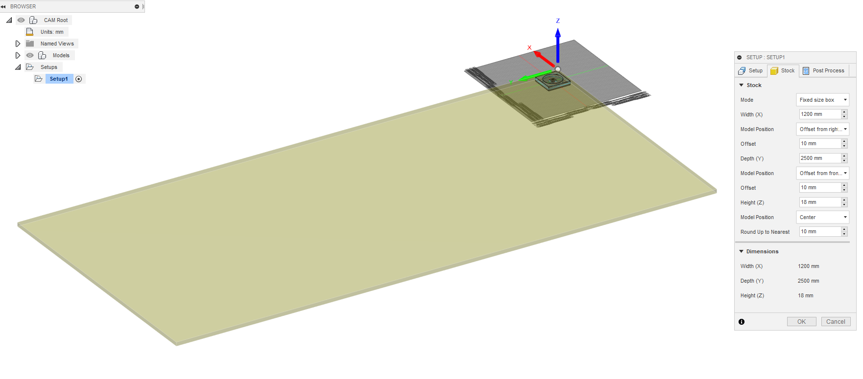
I create a setup and choose orientation (here Z & X), set Z axis, X axis and origin.
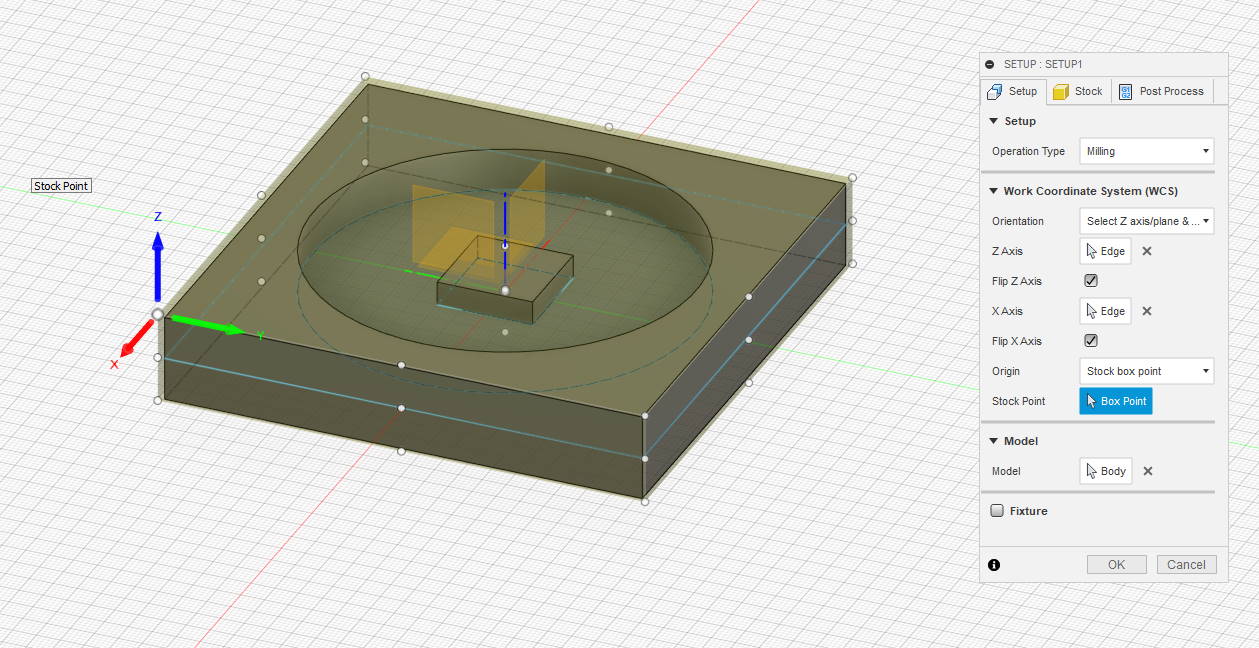
Then I define the stock material (the material that will be milled to have the object) with a fixed size box (designed at the size of a OSB panel). Because I don’t want to mill in the center and lost material, I fix object near a corner of material.
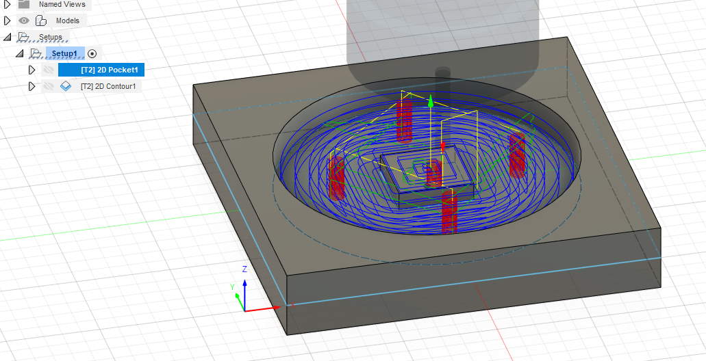
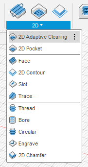
here i will use a 2D milling strategy
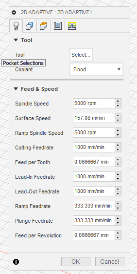
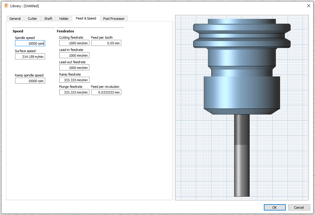
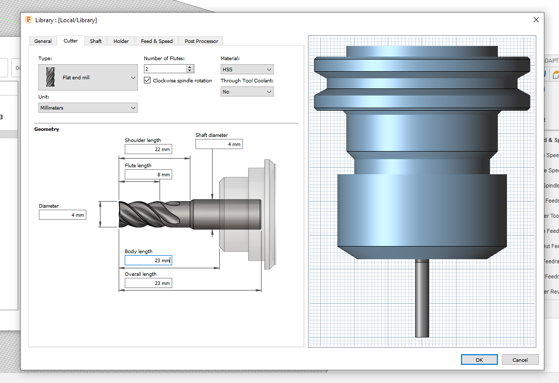
First you have to choose a tool.
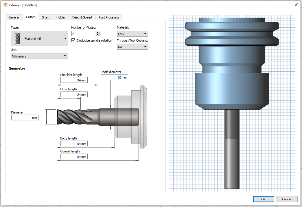
I haven’t tool created yet, so I define a new. First thing to do is measuring the real end mill mounted on collar (for deep milling define precisely shaft and holder is mandatory).
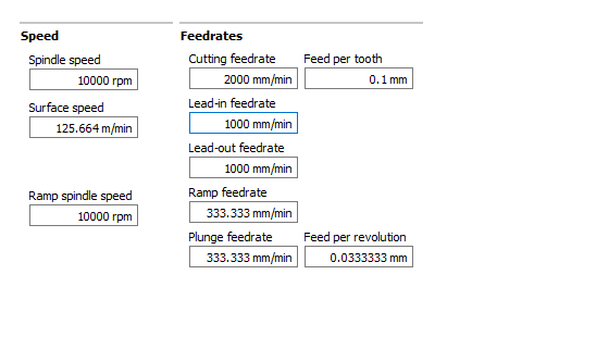
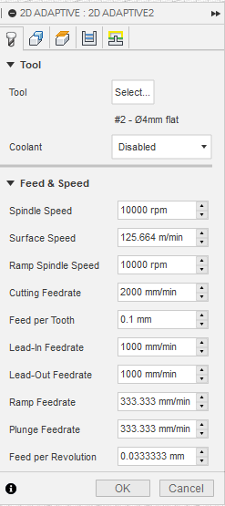
You have also to predefine feed & speed.
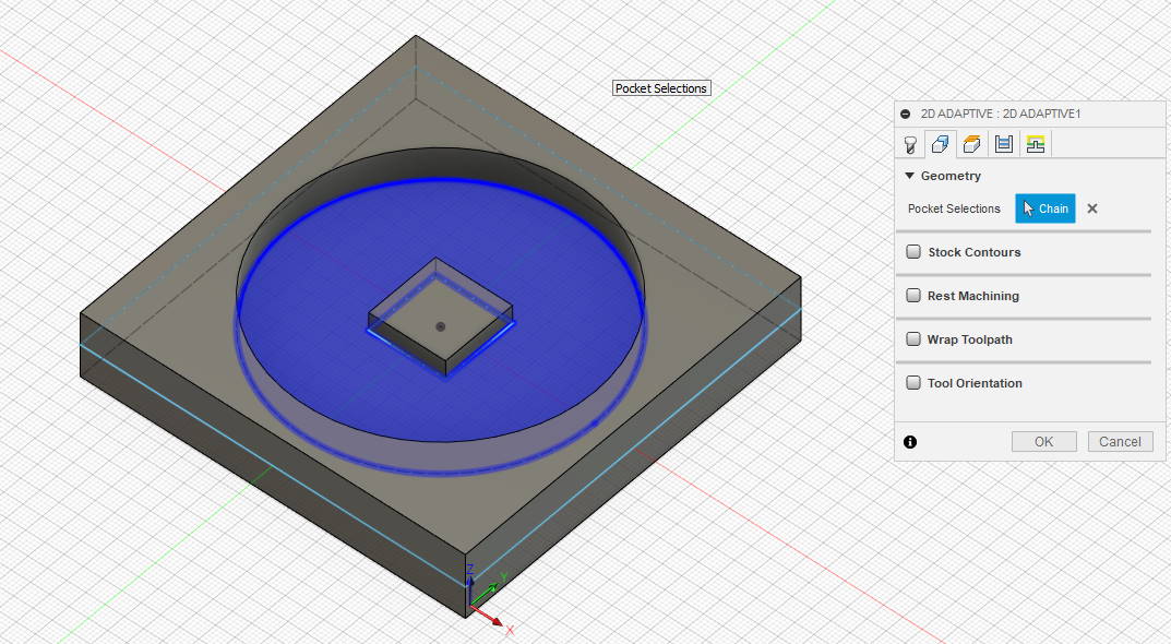
Then you have to choose where to mill
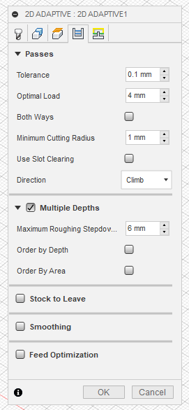
You can also set passes and depths (like milling PCB with mods)
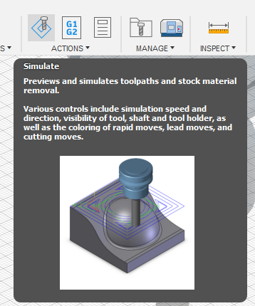
At the end, you can see the tool and his moves
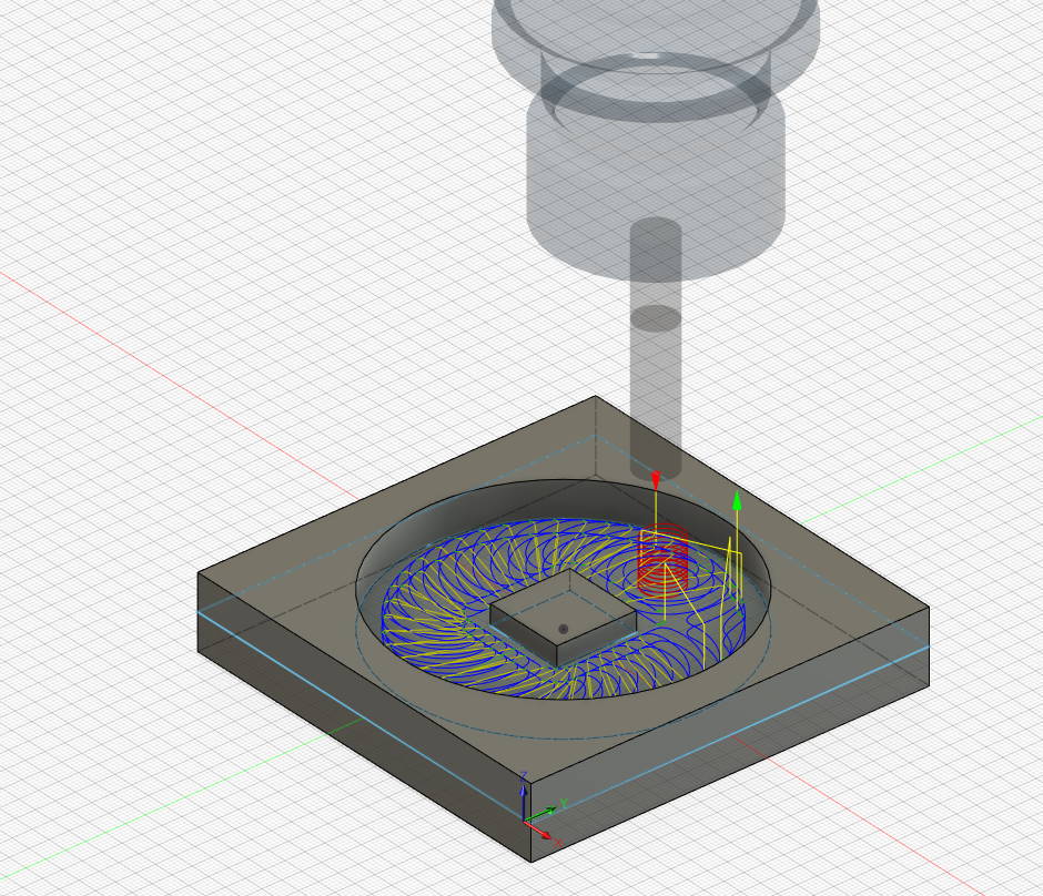
You can see moves by clicking on simulate
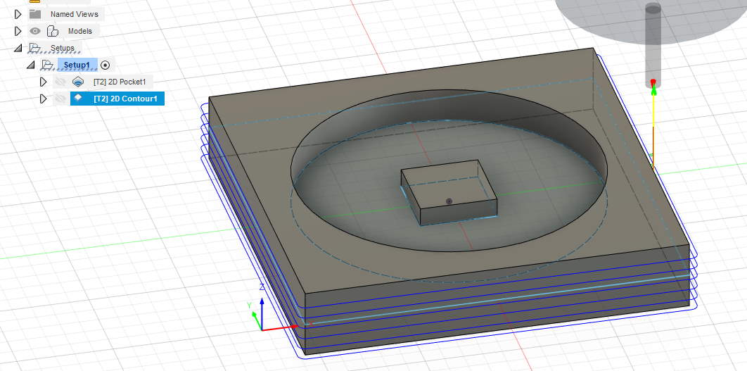
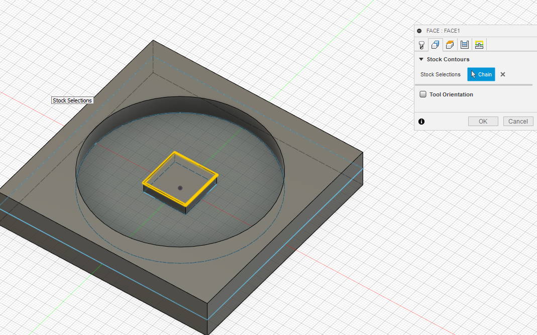
My inner box isn’t milled so I add a face
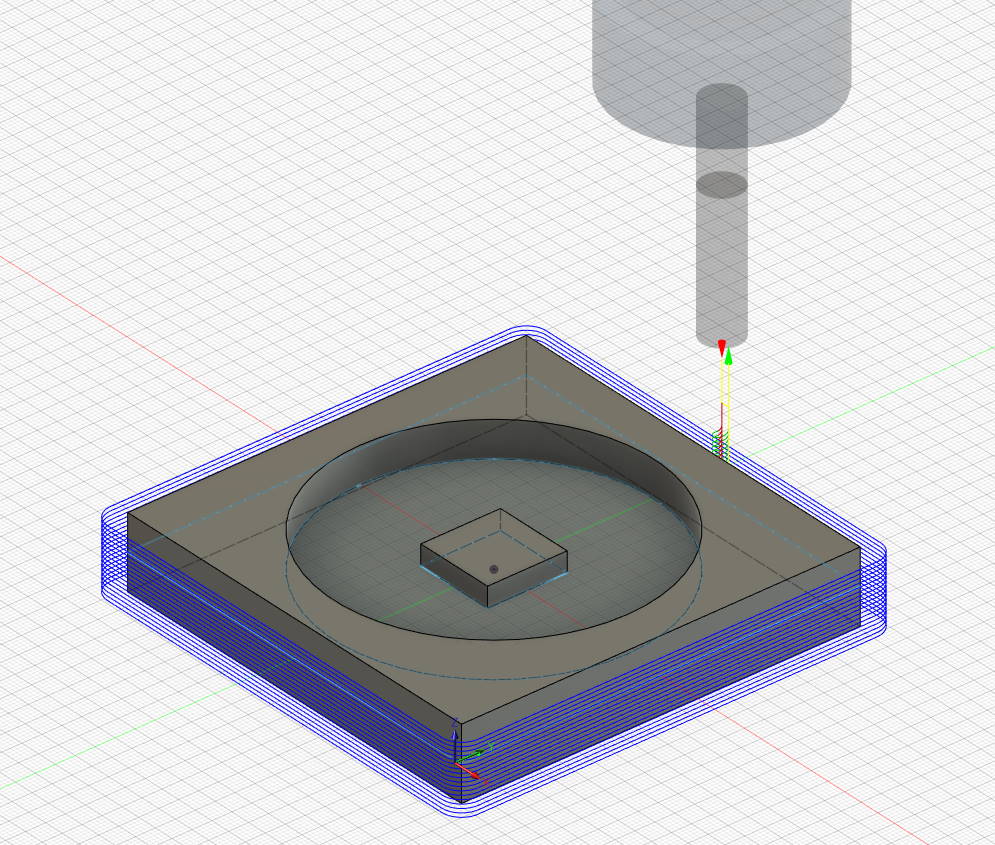
I add a 2D contour milling strategy for outer edges of my object.
When it’s OK, I have to send instructions to the machine. Here it’s Mach2mill
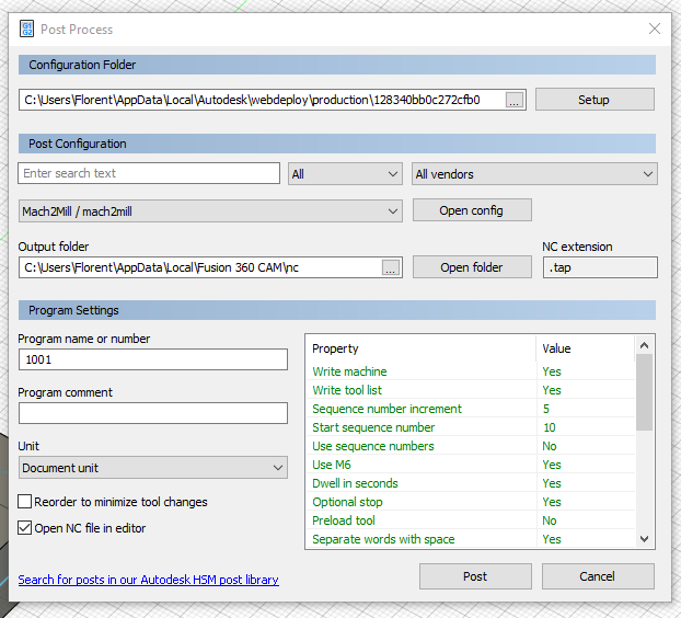
After clicking on “Post” I can see the generated code (GCode)
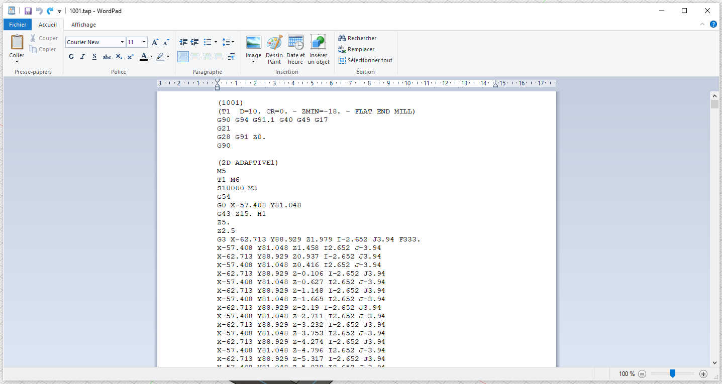
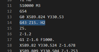
Here I have to remove a line because it add a tool compensation (I need to look on post processor for remove that but no time yet)
G43 Z15. H1
Then I have to save my file with .nc or .gcode extension for the CNC at AgriLab.
Design something Big
For Dogbone, I choose to use a fusion360 plugin here : http://tapnair.github.io/Dogbone/
Installation guide isn’t correct and to install correctly the plugin you have to rename the folder dogbone-master to dogbone or it won’t be detected in fusion 360.
1st idea : catbox for cat show
I’ve designed a cat box for cat show :
Not finished yet. Size : 70 * 50 * 50 cm. I want to use :
- Dibond (aluminum composite panel) 3mm for side
- Expanded polystyrene (EPS) 1cm on top and bottom.
- Front will be in Plexiglas
- Back will be a mix dibond/plexiglass
new idea : litter cabinet enclosure (for final project) v1
Due to COVID and difficulty for buying all material in time, I switch to a design of a wood cabinet enclosure for the litter (see final project)
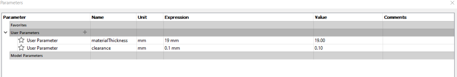
Because I haven’t the wood and CNC at home to mesure thickness and test fitting and clearance, I start a parametric design where I can change value at the fablab without redesign everything.
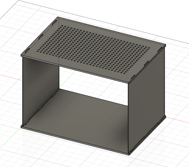
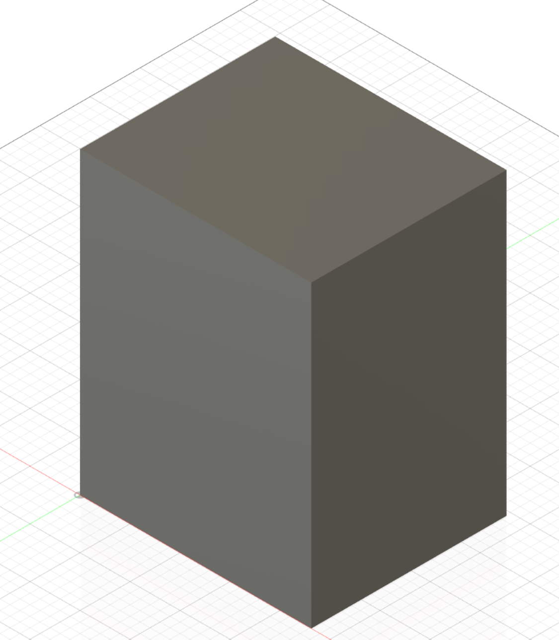
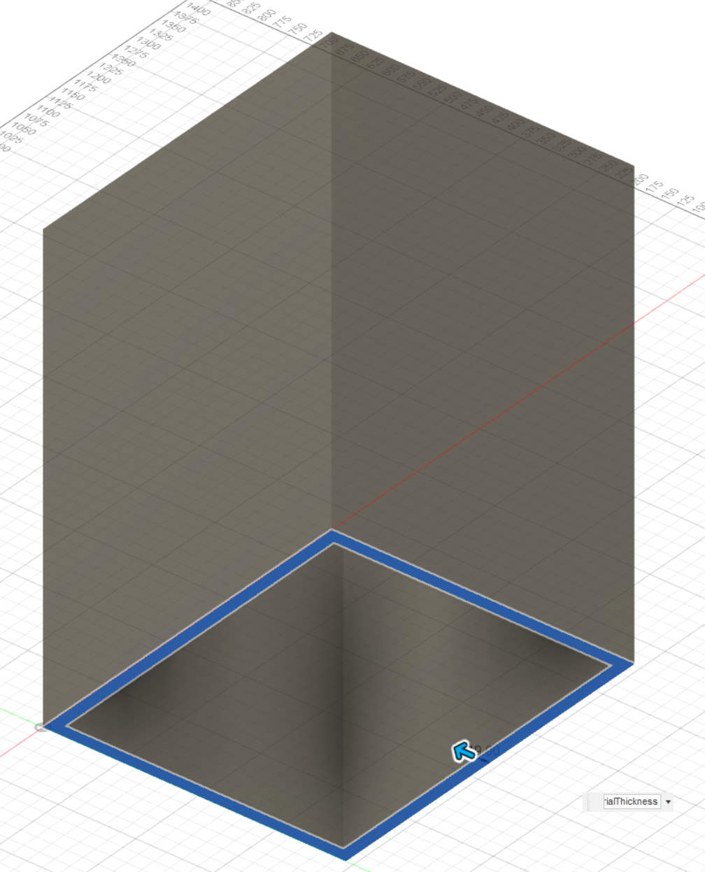
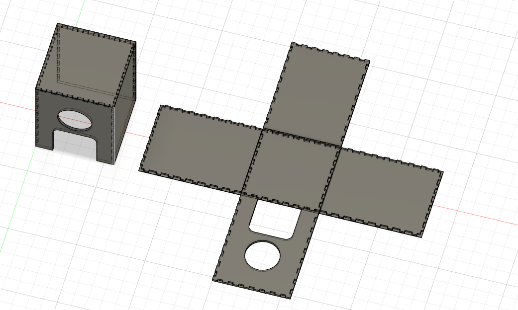
I design a box
then I make it a shell
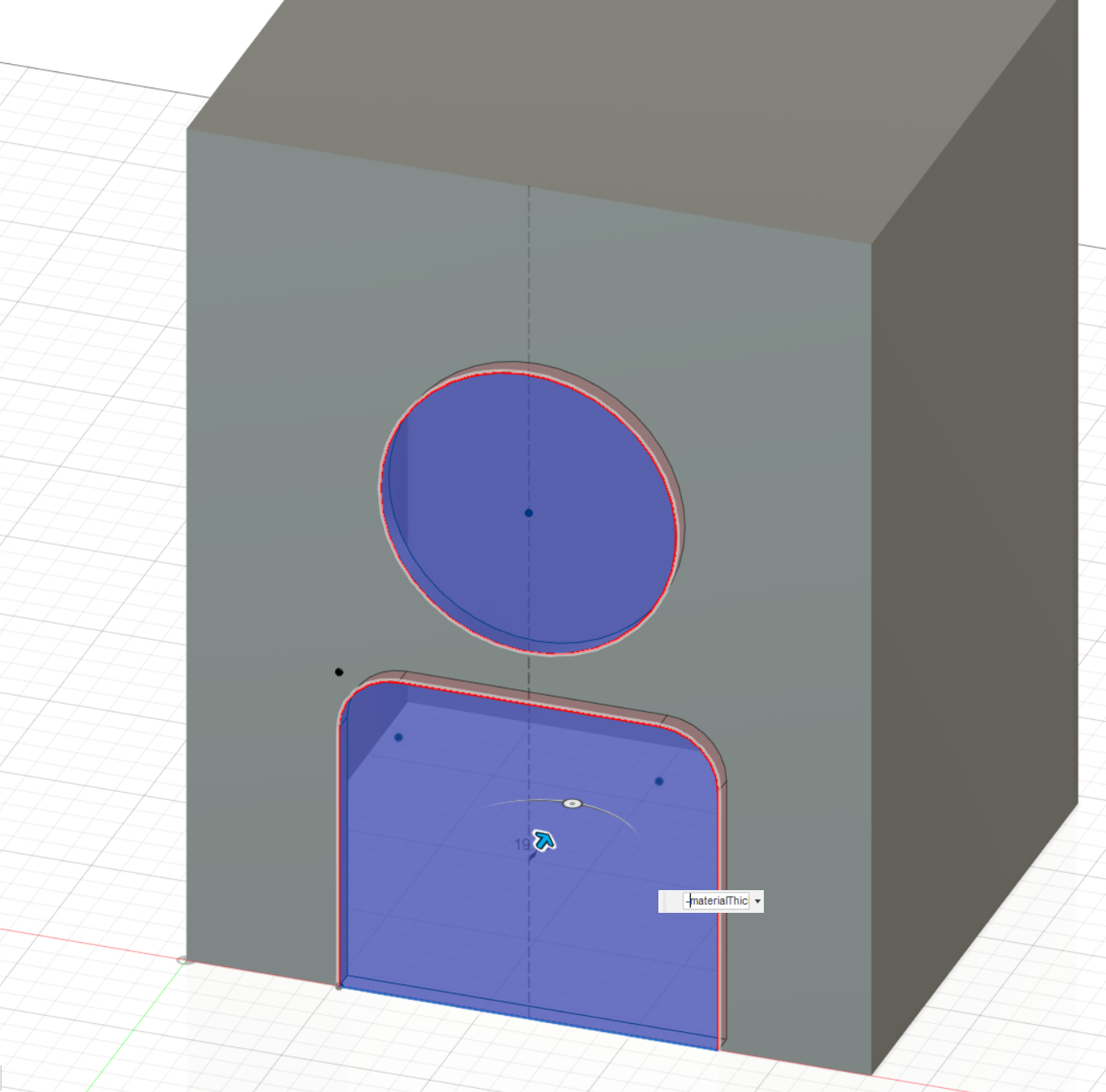
I draw a sketch on the front face to add holes.
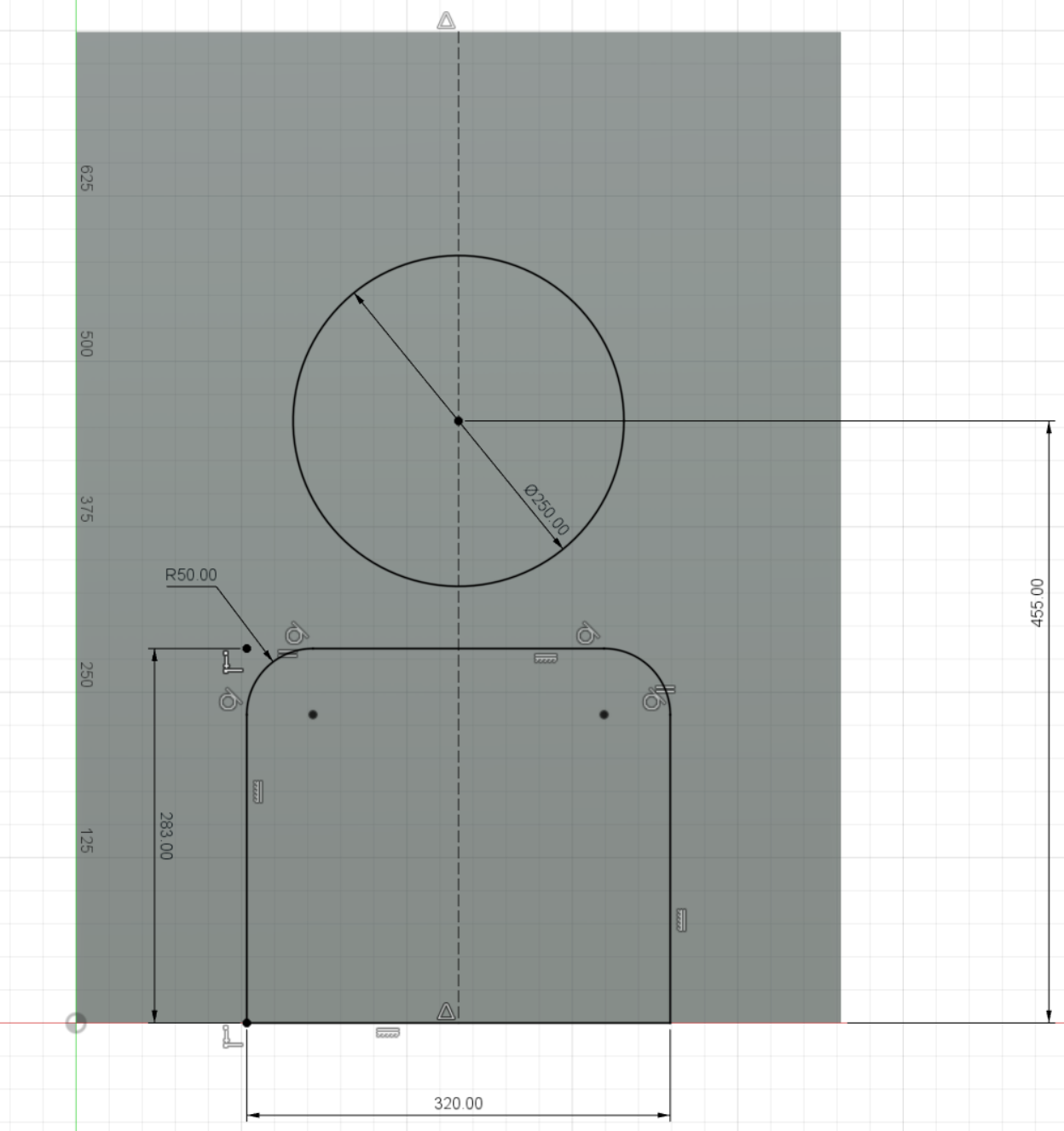
and I remove them
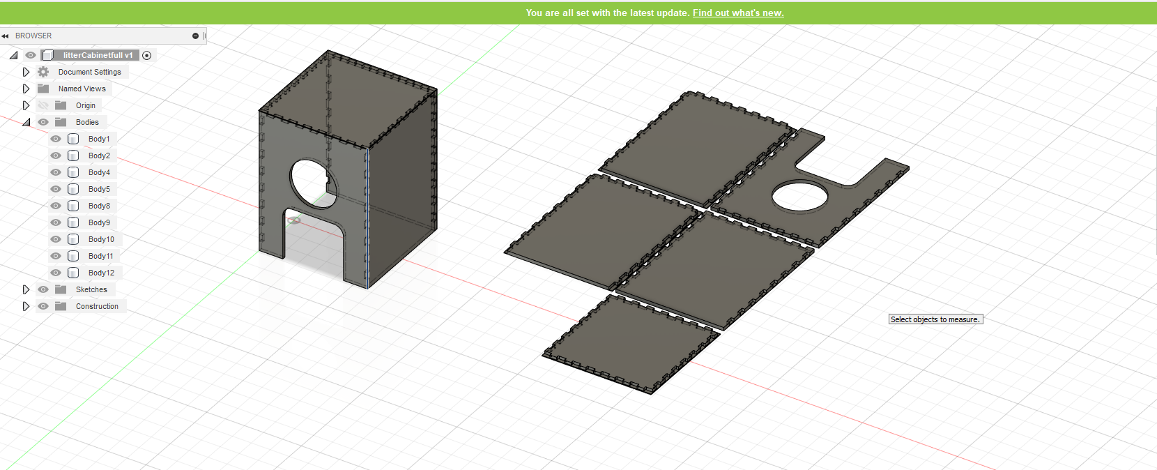
Then I can split faces to have all parts
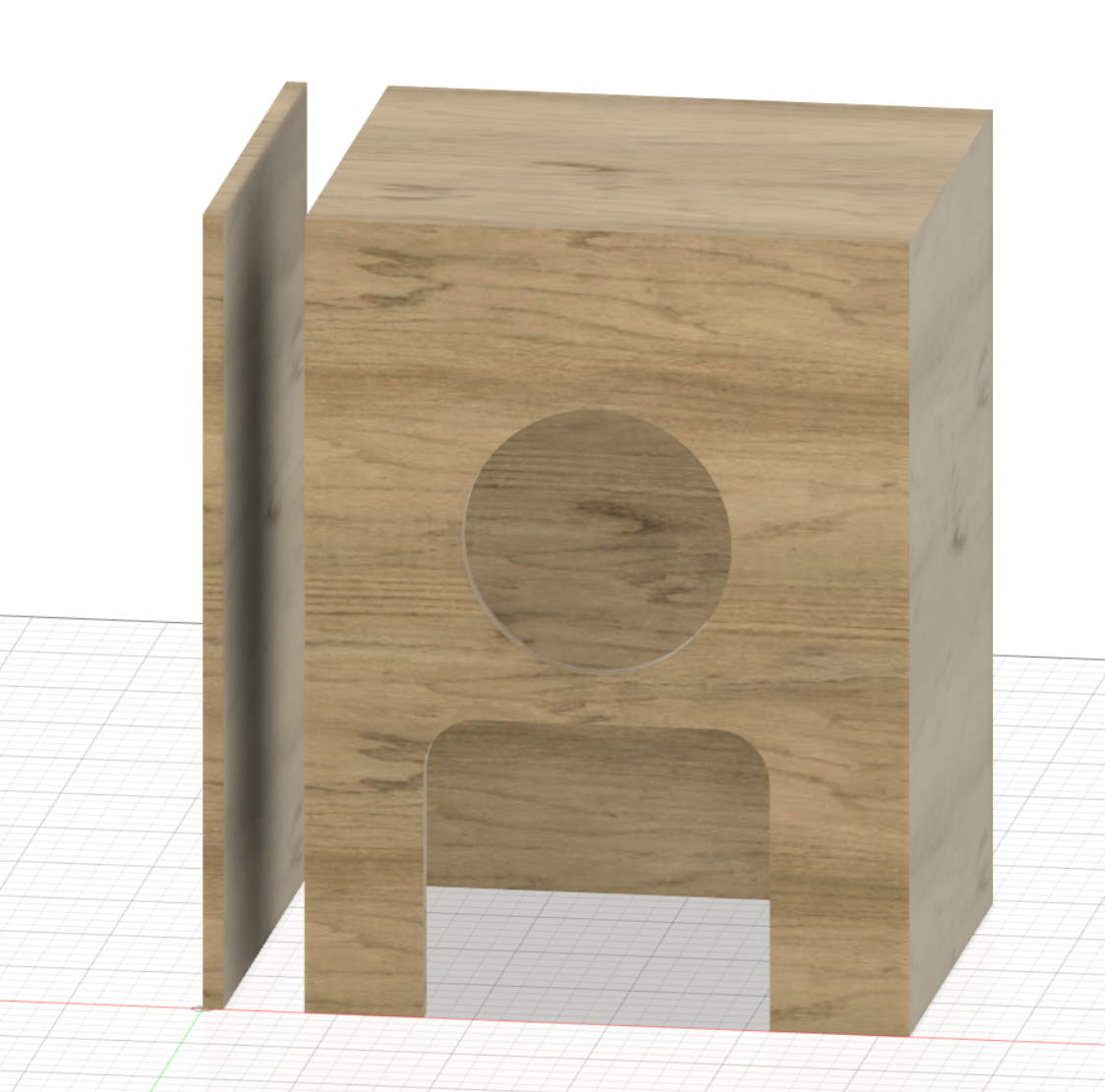
This works good if I want to made a cabinet with all part glued or screwed. It does not work I want to have some joint because I need overlap between faces (at most add material thickness on all sides where I have a corner). So I made another design for this.
litter cabinet enclosure (for final project) v2
Looking on Jochen Groos’ 50 digital wood joints compilation (poster here), I decide to make my own version of secret finger tenons 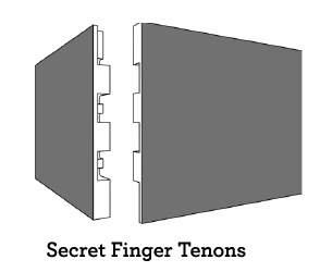
Here a 2d design of the original concept
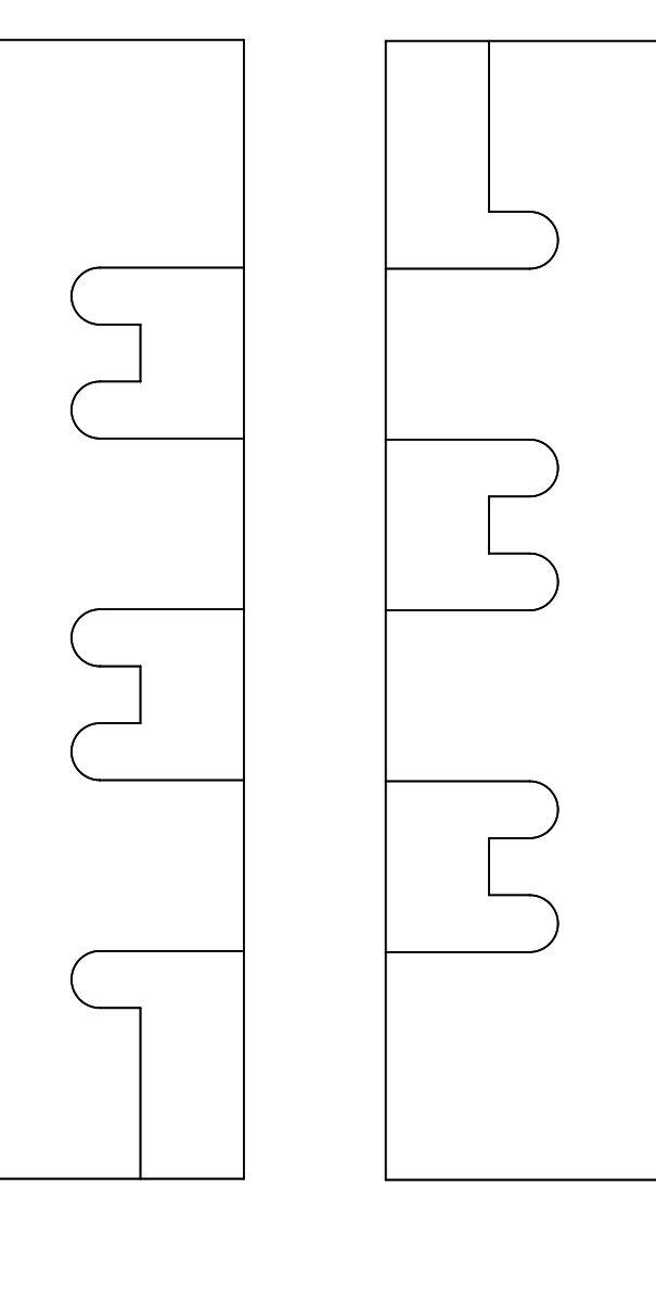
I will change this to this :
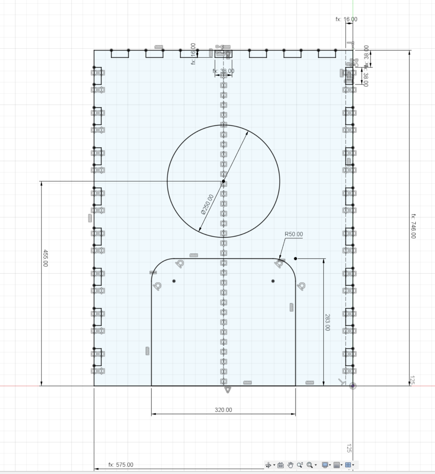
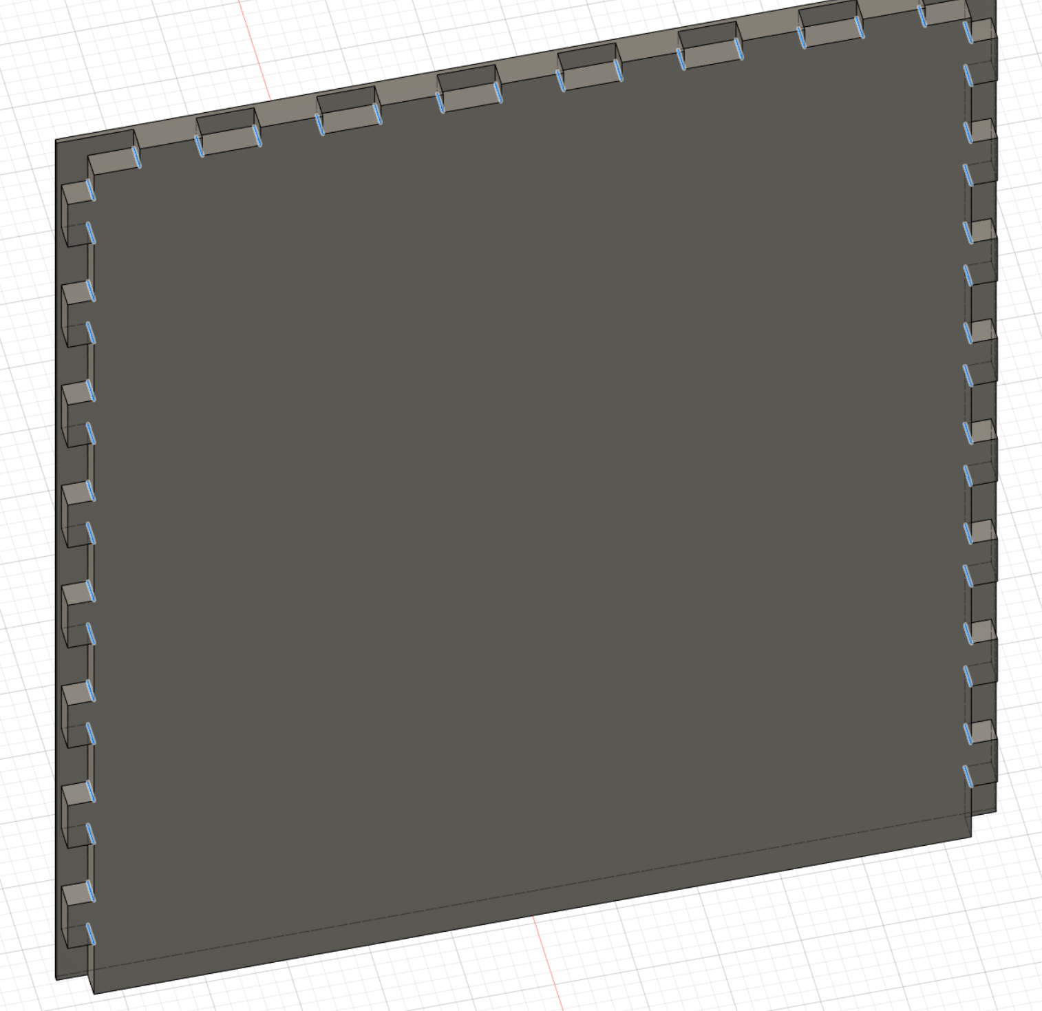
So I design the front face (the most complicated, I can extrude both front & back from that)
Front and back extruded 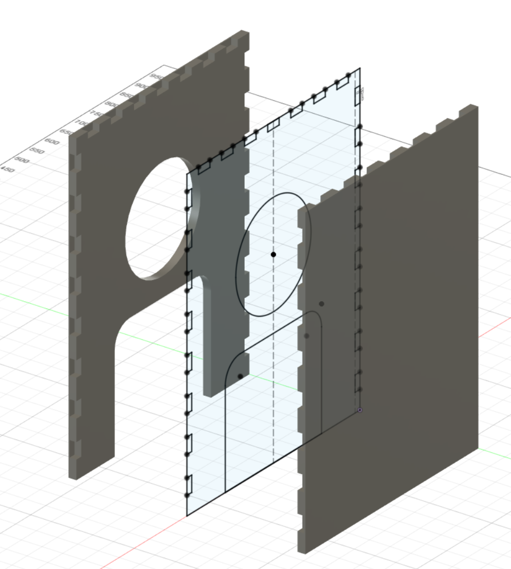
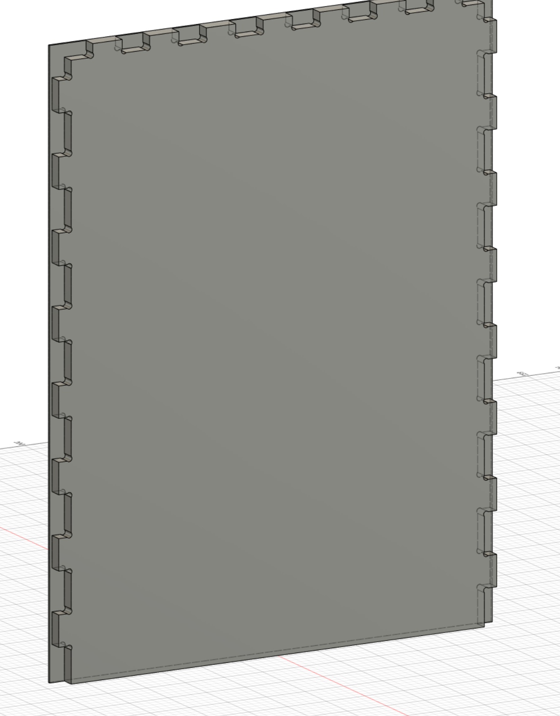
Now I add top, I create an offset plane, project existing bodies and and new tenons, then I extrude the body. For the side, I directly create a box on a side and then I cut with the 3 existing bodies the tenons.
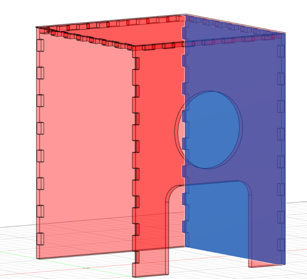
Then I mirror the other side, by first adding a plane a the middle.
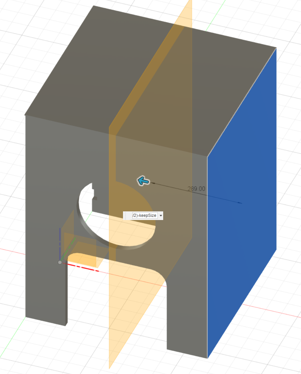
Cutting with multiple bodies seems to have some bugs in fusion360, I have flat planes on the side
So I remove them.
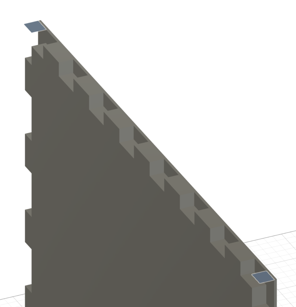
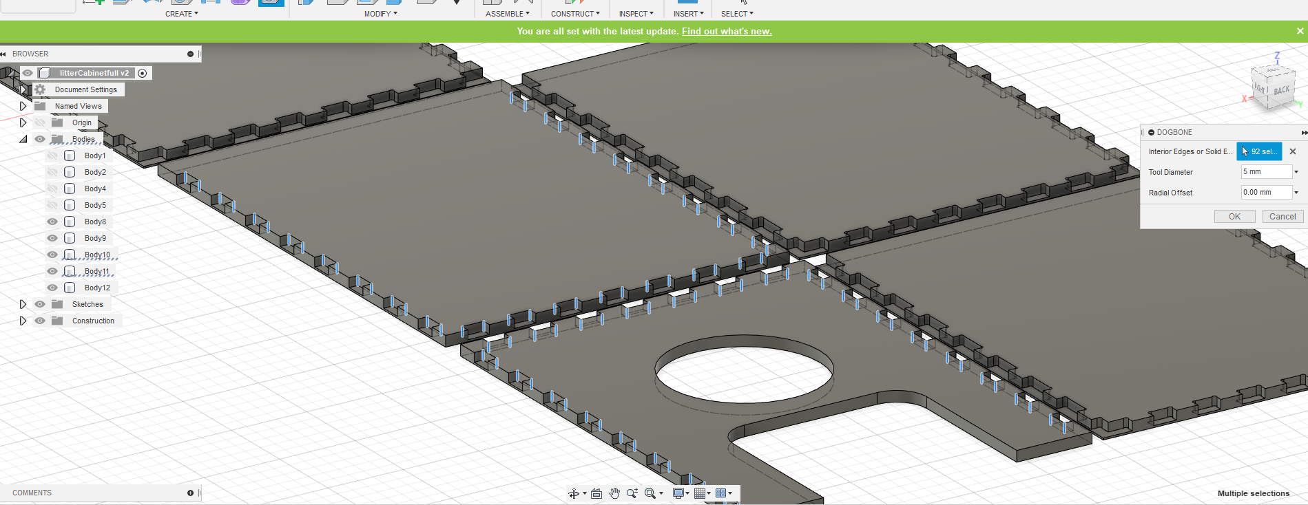
The result is cool but can’t be CNC made. Why? Because inner corner can be made with an endmill, so let’s go add dogbones!
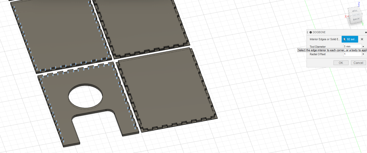
I select all inner corner
And with the dobgone plugin, I have this result
Before continue, when I go back to AgriLab, I start measuring endmills. I will use a 2 flutes 4mm endmill, I have 23mm height available, perfect for my case. So I made dogbone diameters at 5mm.
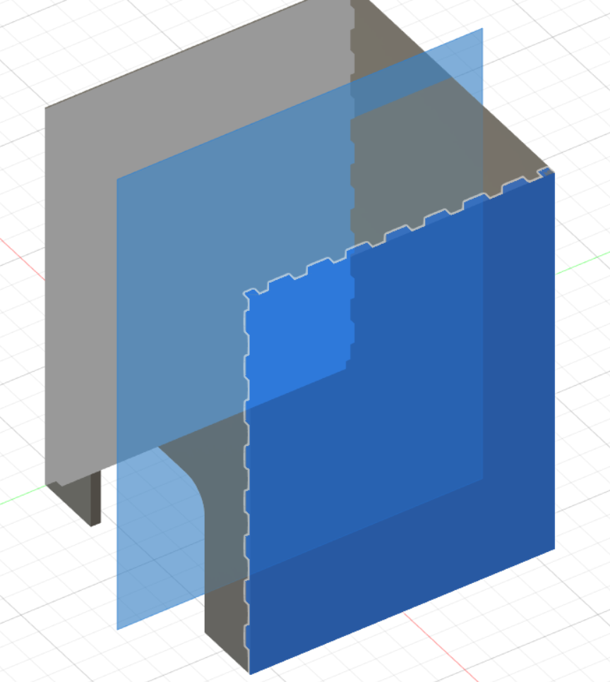
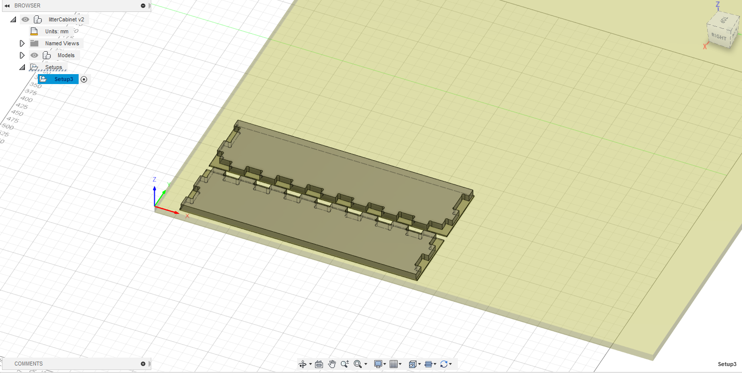
Before milling full enclosure I made a sample to test fitting. For this, I create a box, then intersect 2 faces on my enclosure. Then I copy bodies to a flat version.
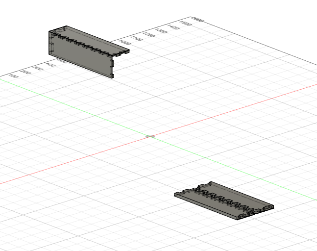
Now with this copies, I can generate my toolpath.
Back to AgriLab, I take measurement of bed and also material. My final material is wood at 250x122x1,8 cm. MDF is 300x120x1,8cm. Bed size of CNC is 250x120x20cm but length is not really 250cm because of a tool changer, so I count 240 to avoid collision.
To be sure all will be milled, I set my stock size at 18.1mm because sacrificial material was removed for milling another thing (that’s why I mill my molding & casting week before this), I will reuse it on CNC without facing all so I take 0.1mm of security. It really low but I take the risk (I’m here to try!)
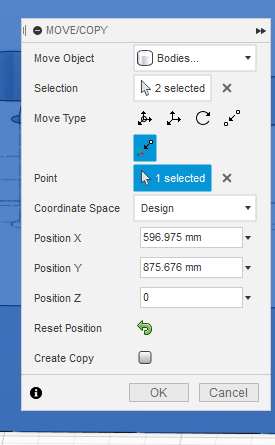
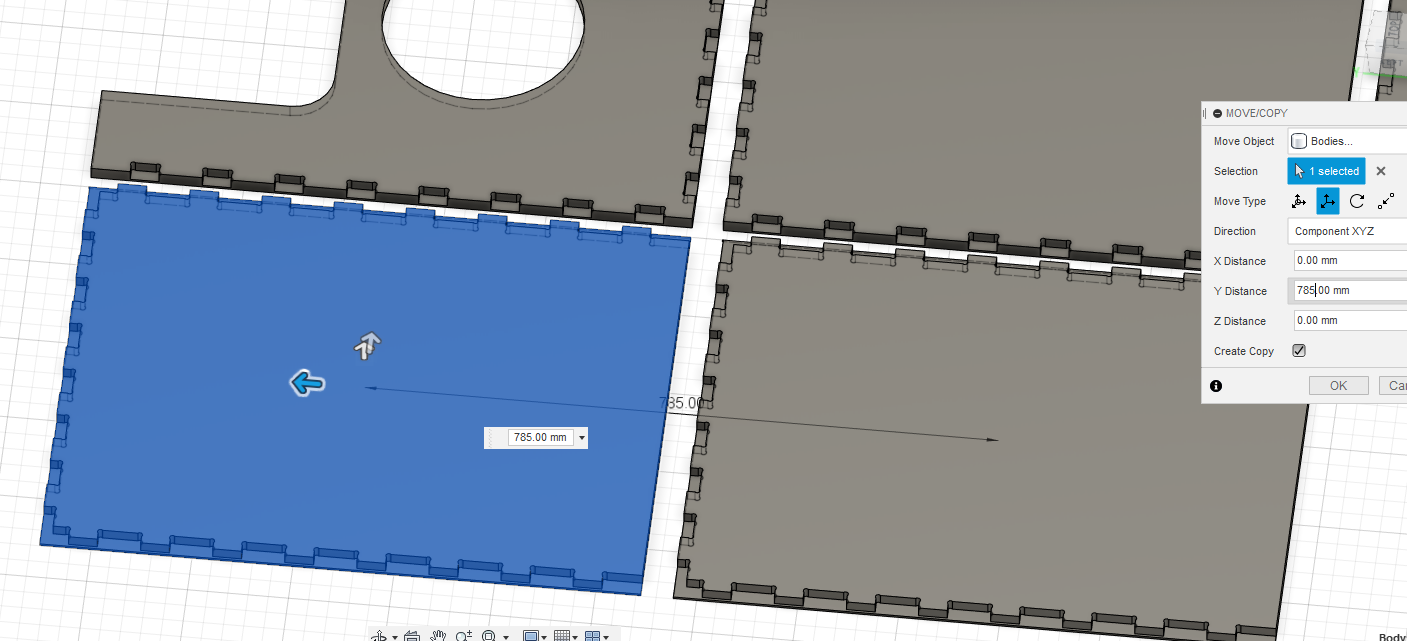
I have a little problem when I generate my test of joints, copies of my parts was not well aligned and I aglin align the 2 objects. Now they are good but I have problem when designing stock material, objects was at 2,909mm on Z axis… hard to find! so I move objects with this setting to put at 0 on Z axis.
Now my setup is good, I pay attention to correctly set all axis (because I invert the CNC weeks, I made the milling of my casting & molding week before this, and I invert X & Y axis, but thanks to my low profile holder & the overall shape on my mold was a square, I just have to move the 0 point for X & Y without regenerate all Gcode )
Fusion360 crash and I can’t recover all my previous milling part, I have to redefine my endmill…
Windows force an update with reboot and I lost again… I have to remade all milling again… In the same time, I measure material. MDF is at 18.6 unstead of 18mm. Plywood is at 17.8 unstead of 18mm… Because my design is very dependent of thickness, I finally directly test plywood.
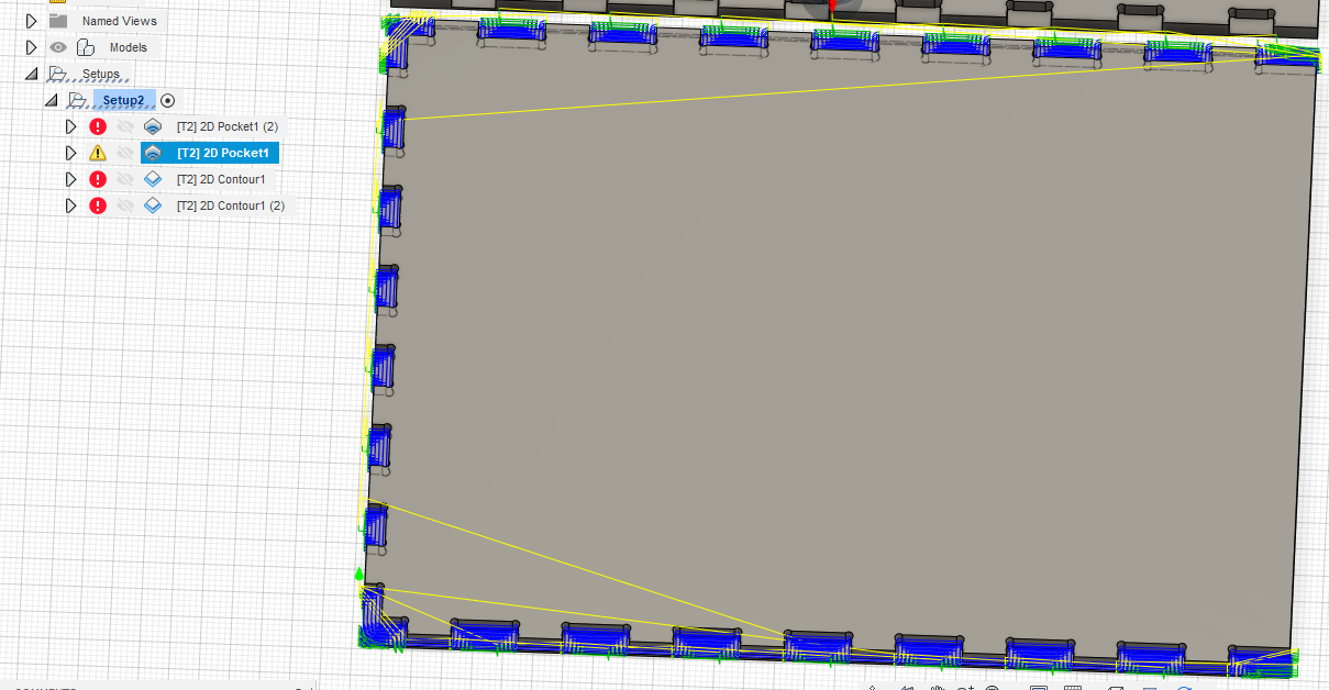
I use 2 2D adaptive for milling inside on my dobgone.
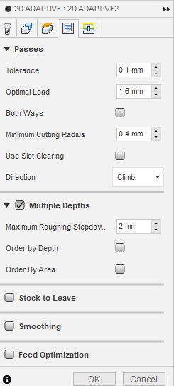
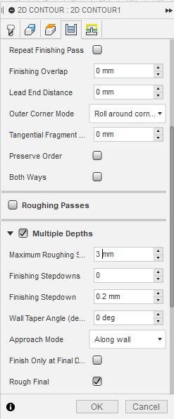
And 2D contour to cut my parts
and change 2D contour to 3mm depth pass
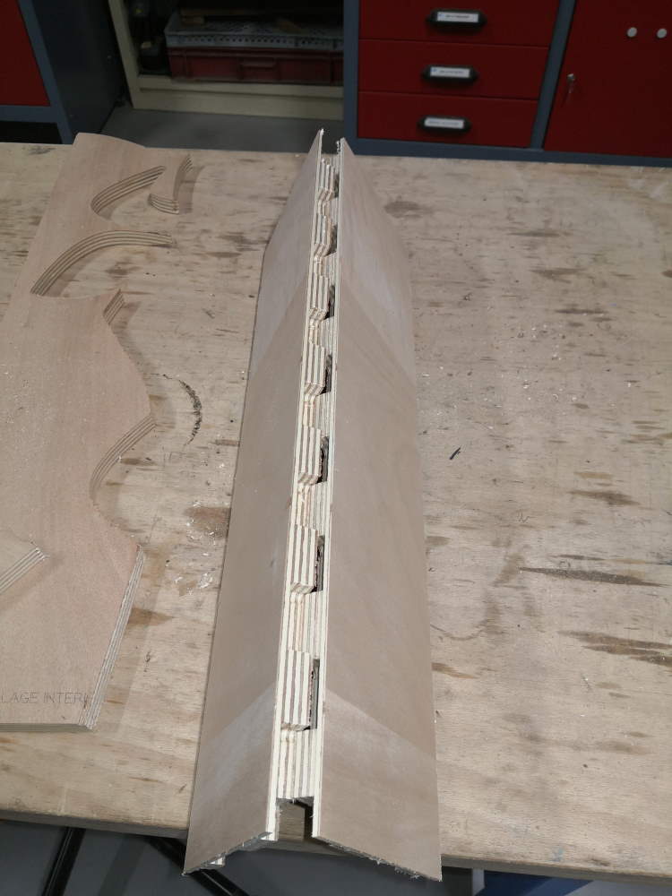
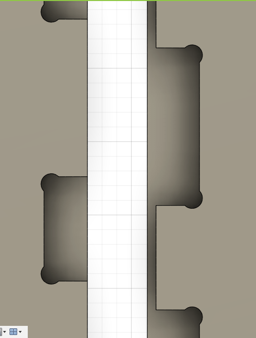
When milling my joint test, I see CNC make too many moves in Z axis and also in the air, big loss of time. This milling strategy is cool but seems overkill in my case, wood doesn’t seem very stressed. I will switch from adaptative to 2D pocket clearing to save time (I have finished my milling test with 2D pocket because adaptive was too loooong).
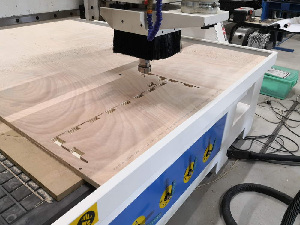
Here, I stop my test with adaptive before switching to 2D pocket (2h for this!) and only 15min to finish!
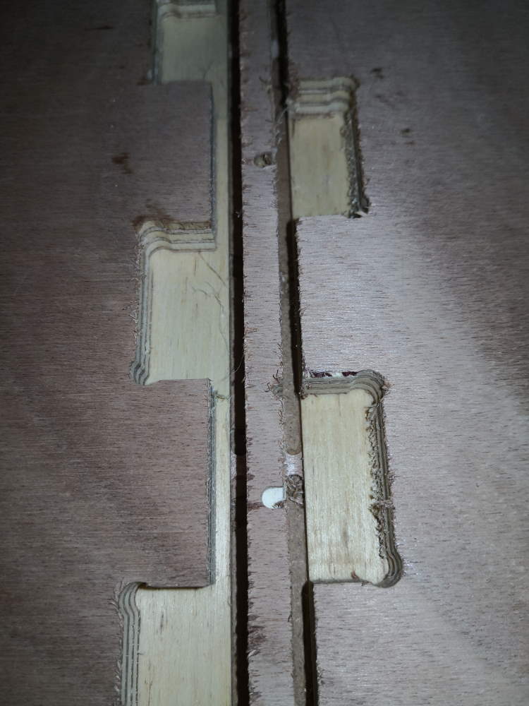
We can see here adaptive on left, 2d pocket on right. Adaptive is a bit rough but this will be inside on my object so I don’t care of perfect smooth finish. My object will be bigger than that test so time is important, I keep 2D pocket!
To finish my test, when milling is finish, because wood is not perfectly flat, I create another 2D contour without multiple depths. I set Z0 a bit lower on CNC et restart this part. First time, 0.5mm lower, good but some parts not fully milled. So I make a second run 0.5mm lower again and all is clean.
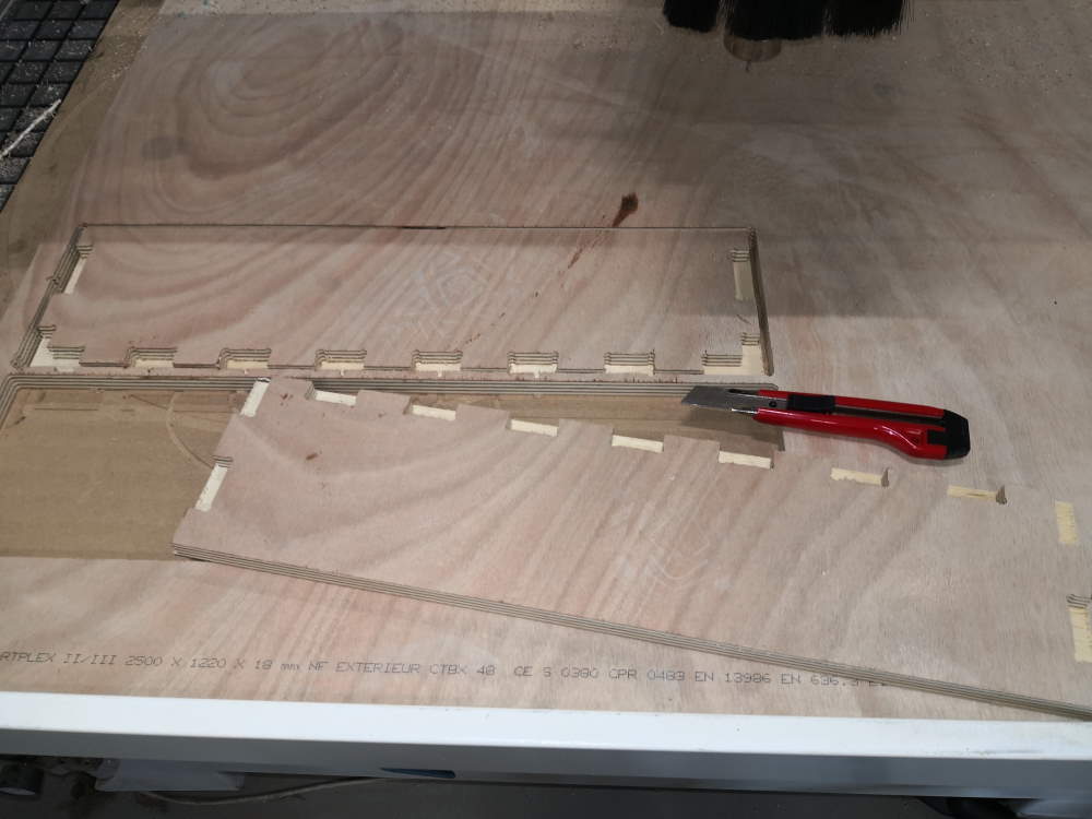
Because I have set tabs on contour, I use a cutter to cut them and remove my parts.
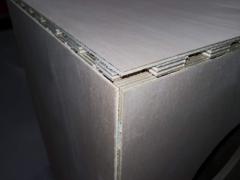
Now I test my joint with this 2 demo parts. I start by hand, no need to chamfer.
I continue with hammers (it’s a press fit!) and piece of wood. Never use hammer directly on wood, you can mark or explode it.
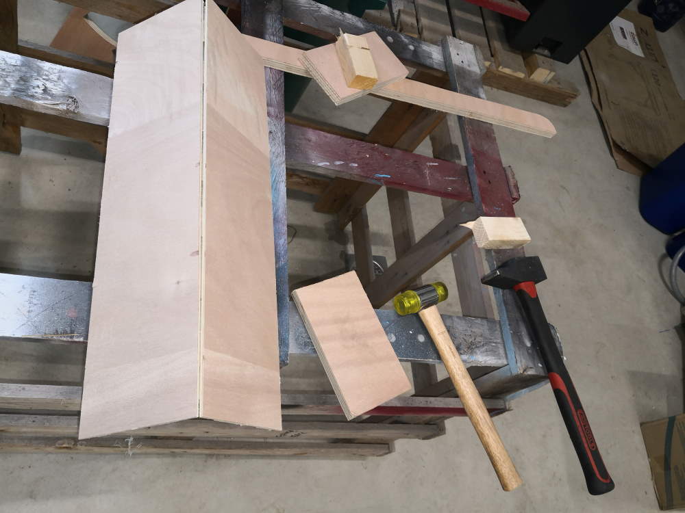
And the result is so cool!!!
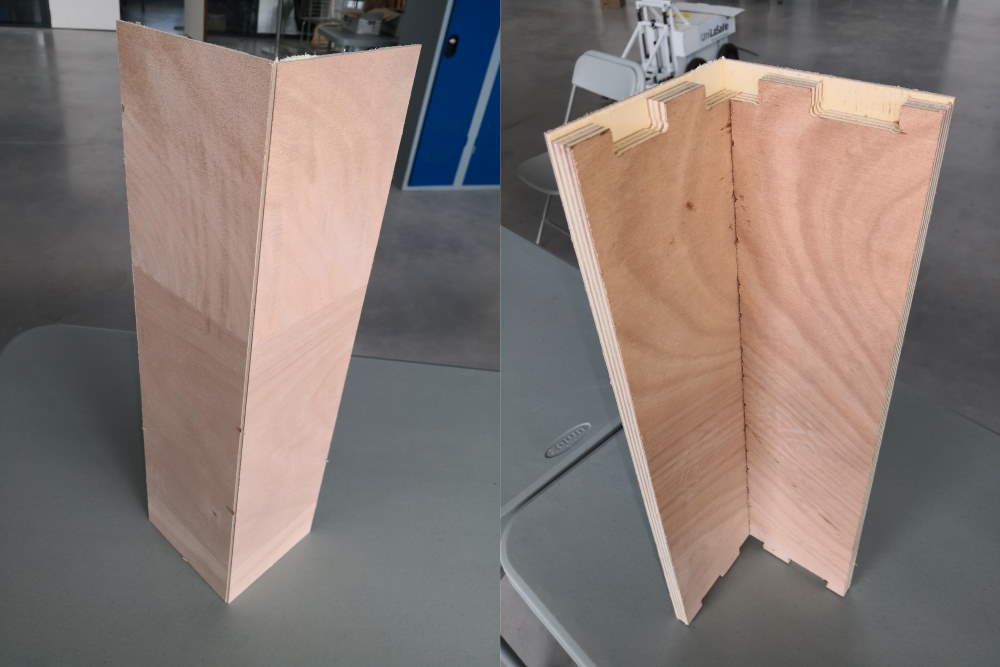
Joint test works perfectly. Go back to design and create full version. In fusion, I duplicate my project and rework on it, I remove the last part with the demo joint. I copy bodies to make an exploded version
Now I place all parts to fit in my stock material (I keep clear bottom left because it’s here I have mill my demo test).
Ooops when creating my milling strategy I found I have forgotten some dobgones on 2 bodies because I stay focus on joint testing… I add them directly to the flat version. I recreate dogbone with tools diameter at 5 and radial offset at 0, finally dogbones looks smaller. I also forget last time I’ve add 1mm offset. So I retry.
good version
now it’s good
I found a little bug on fusion:
Even if I select all stuff to mill
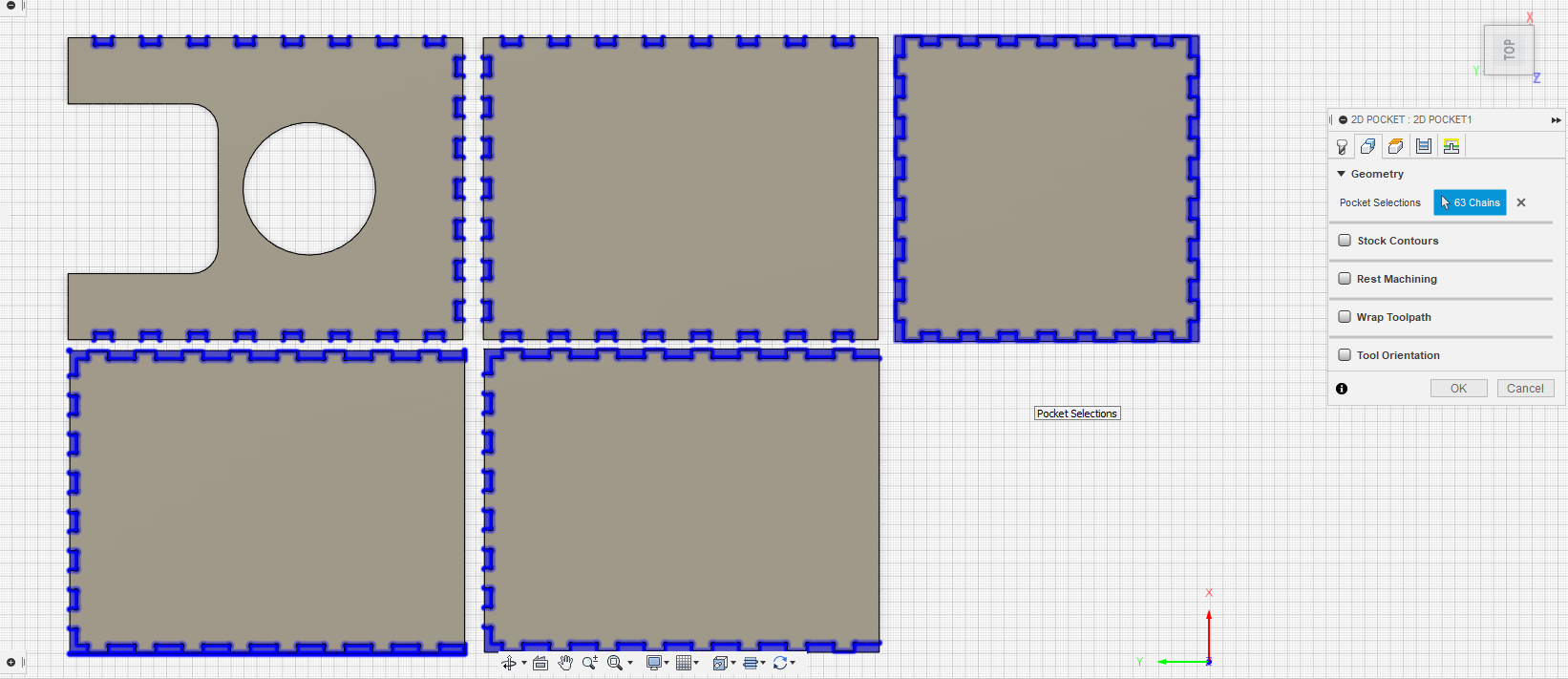
I have a side not milled
I try to add the missing part in another 2d pocket, same result, I try an 2D adaptive, won’t work too… It very strange because these piece is just a copy of exactly the same on right and I have no error on toolpath…
I move bugging body out of working surface and hide it (I can’t remove it because it destroys timeline of fusion) and I add a clone of the working one instead.
I quickly test same strategy on the new body and it works fine…
And now it works, very strange behavior
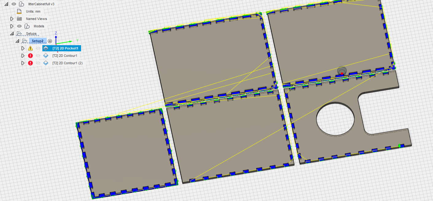
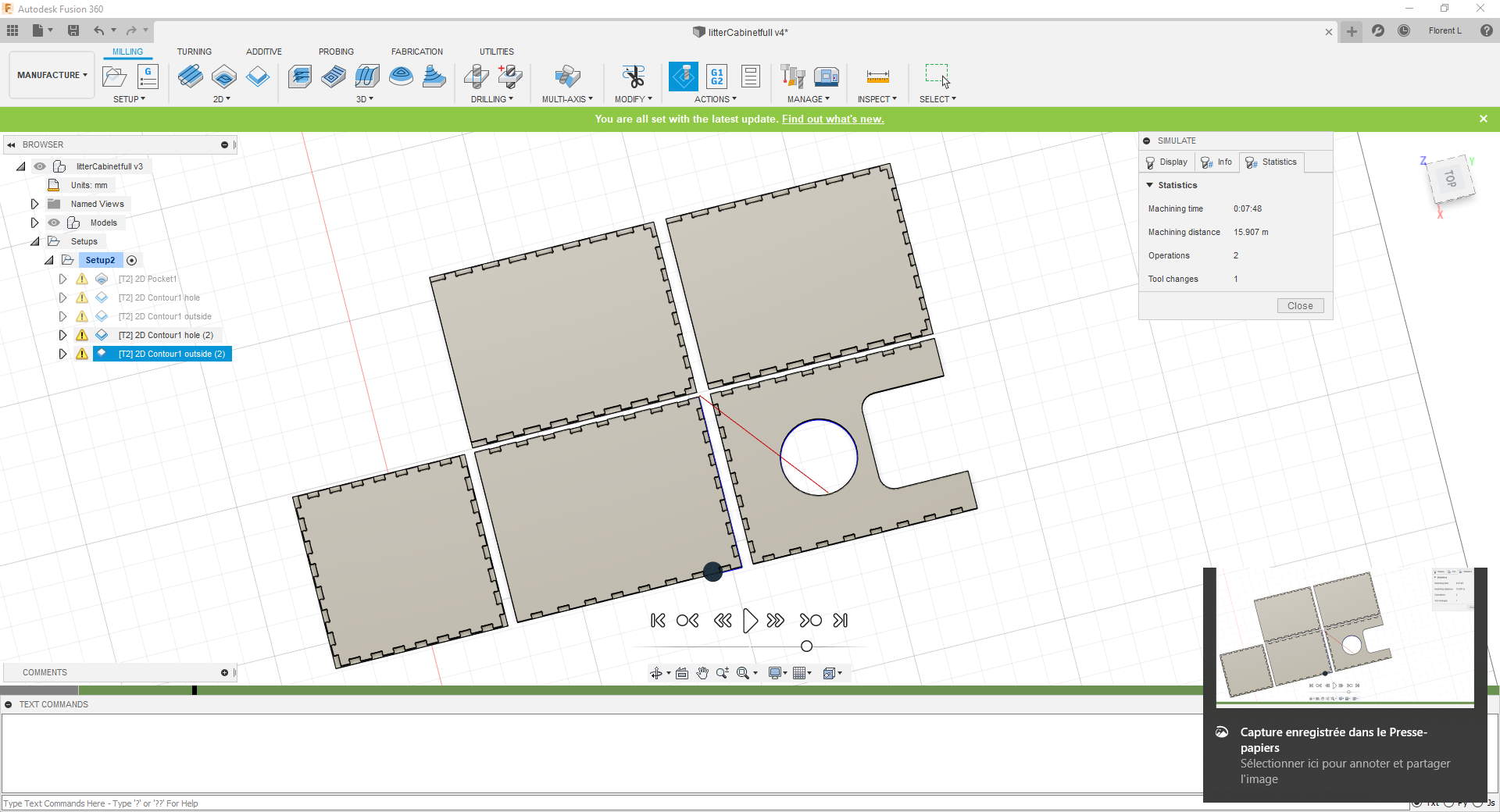
I add a 2D contour for the big hole, to mill it first
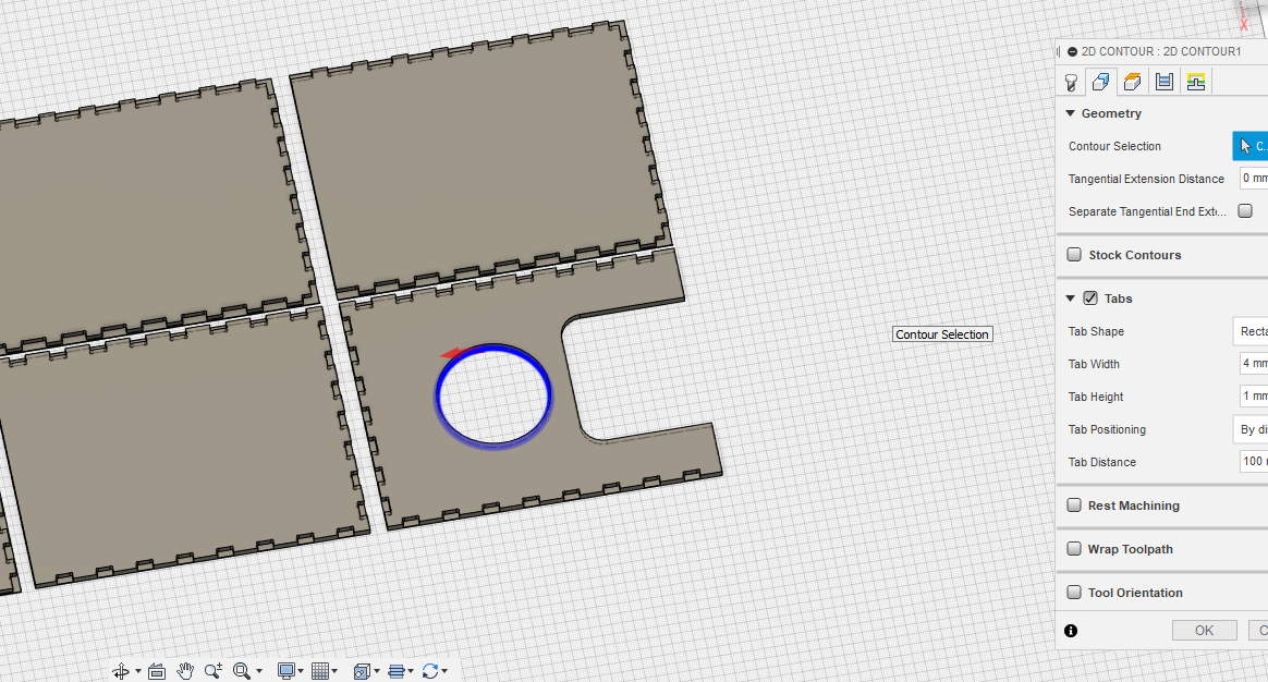
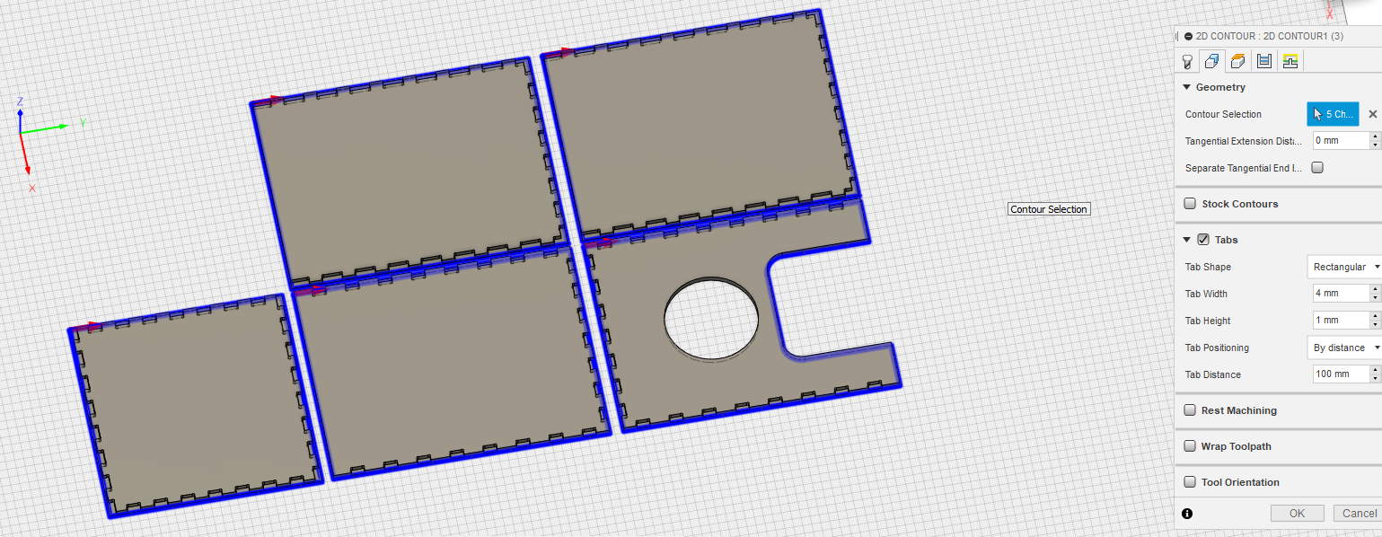
and after I add same 2D contour for outside, by doing this I’m sure the hole will be processed before outside
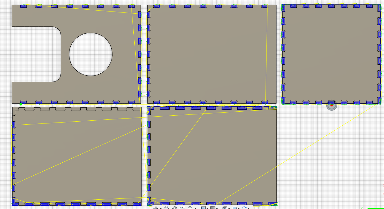
Now I simulate :
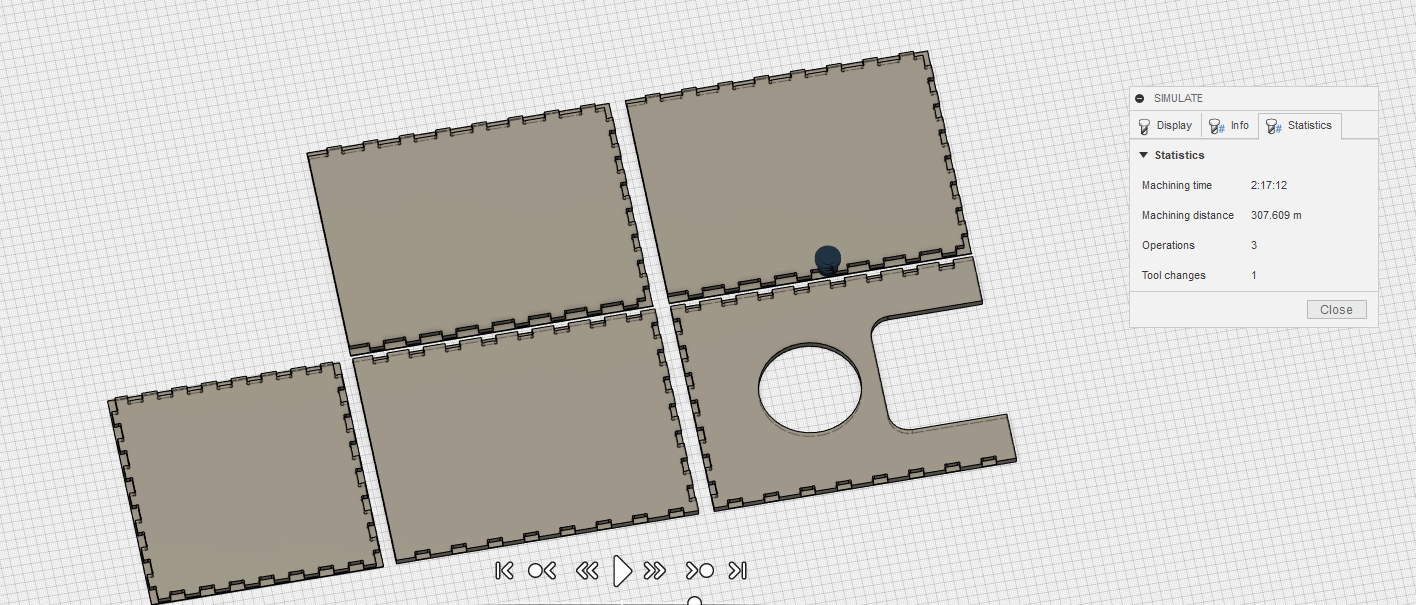
All is green, I change depth pass of 2D contour from 3mm to 4mm and save 15 minutes.
I export my file, I remove the G43 line as usual. Then save it to flashdisk.
It’s finished but like the test, I have to add a contour a little deeper to finish cuttings the parts. I directly create another contour, this time I don’t put tabs because pieces are big, no multiple depth, I do same settings for hole. I set the Z0 manually 1mm lower on the CNC and relaunch
A quick simulation, all green.
Let’s go for 8 minutes.
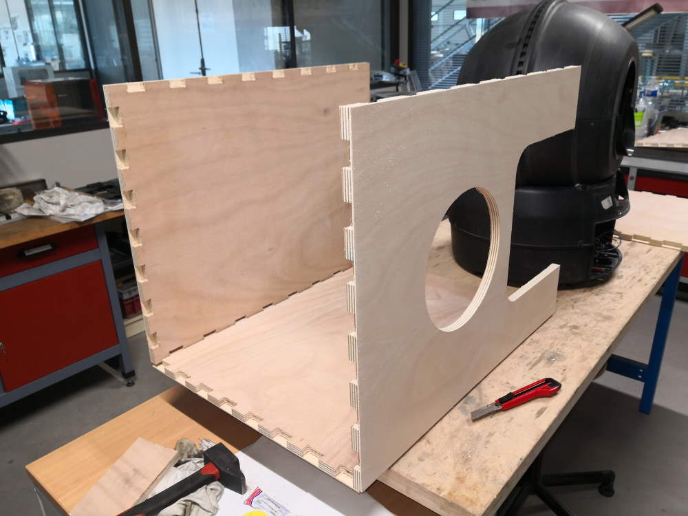
And the result :
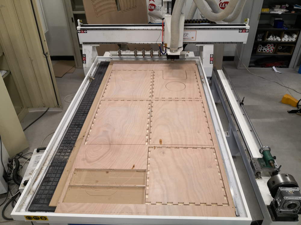
Make something big : Challenge accepted!
Ok, it’s milled but can I assemble it?
First, I test with my litter if the size is good. It will be useless to spend time for assembly if litter can’t fit in.
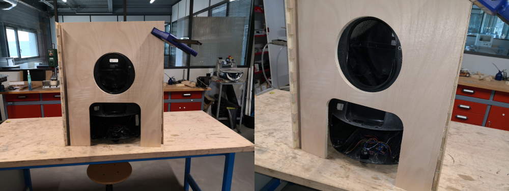
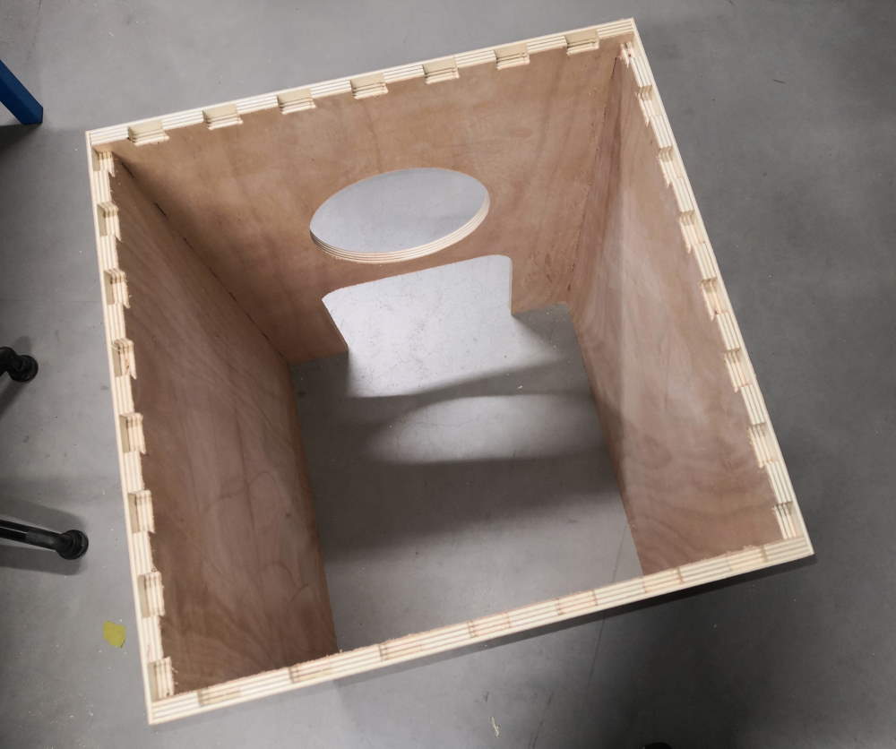
I mount 3 faces.
I put the 4th face, fine!
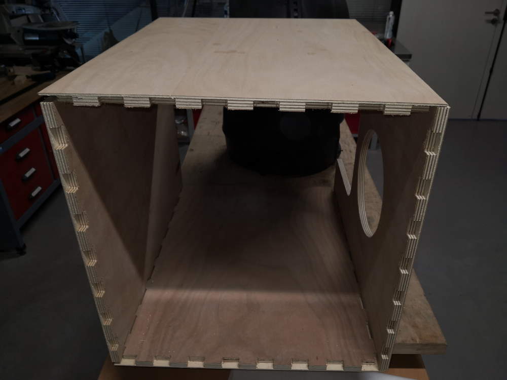
I test the top cover, I verify all tabs are aligned.
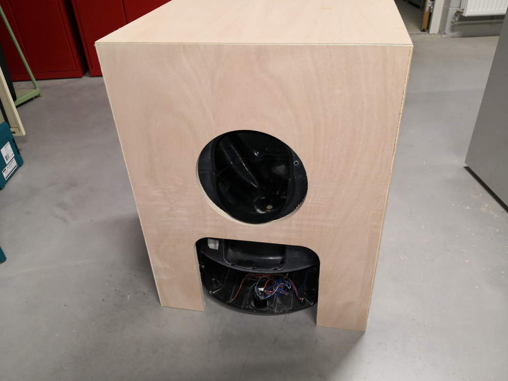
I remove the cover, I finish to press fit with an hammer & a wood piece the 4 sides.
And I put and fit the top cover and in bonus test load resistance.
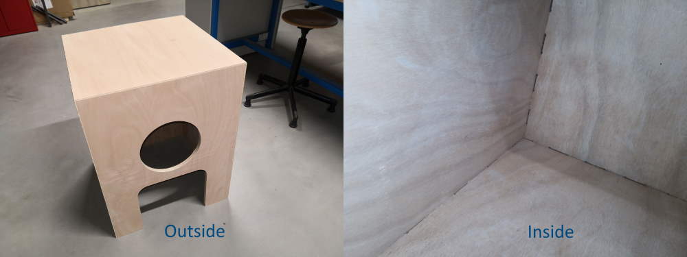
The litter fits inside!
Attachments
Litter cabinet 1rst version (glue or screw) : litterCabinetGlueOrScrewedv1.f3d
Litter cabinet with secret tenons fingers (full) : litterCabinetfullv5.zip
Milltest : millTest.f3d