15. Mechanical design
Goup work
Group work Our group was Gleb, Marjo, Lucas, Arash and I.
Individual assignment
Cup holder.
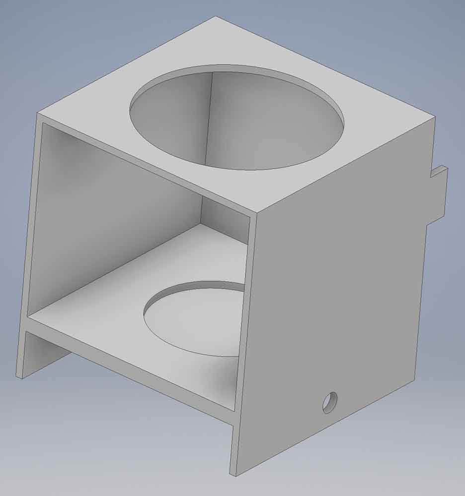
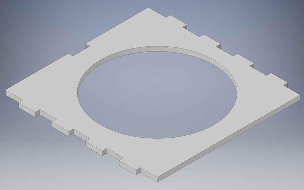
As a part of The Tablet tablet dispenser, I designed the cup holder. The cup holder needs to hold the cup and the movement from side to side comes from a screw rod stepper motor.
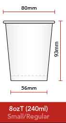
First, the cup was measured. The cup was determined to be a standard cup. On top, there is a place for the cop and in the bottom, there is a hole for the screw rod. And hidden space for the bearings.
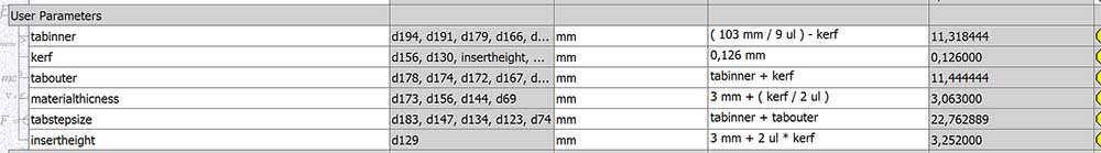
From the sides, a new plane was made and to the new sketch was drawn on the plane and the mockup model was used as a guide. The sides are designed to be laser cut so the tabs of the cut for the MDF was made into parameters.
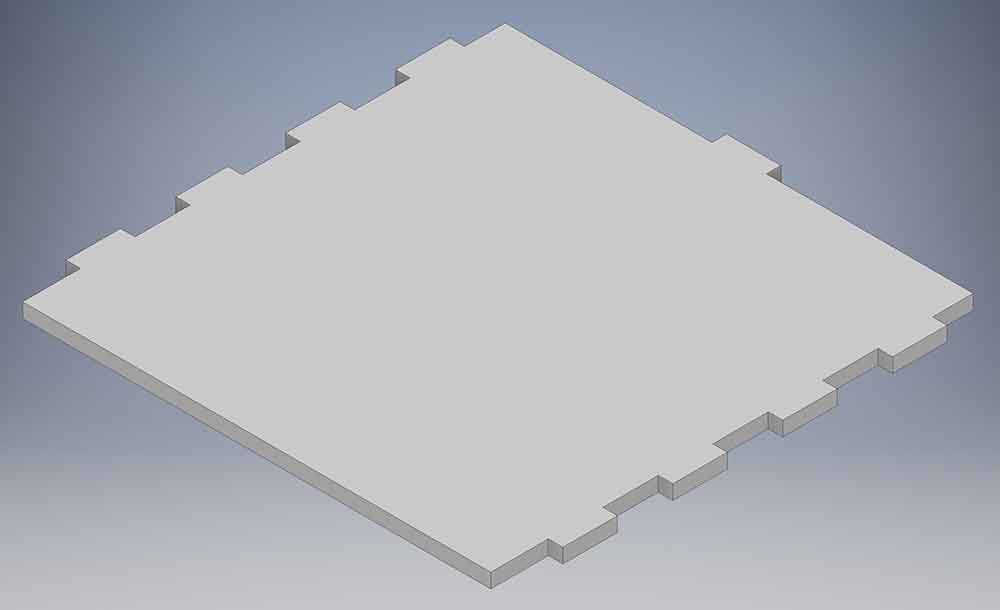
From the sides the laser cut planes are extruded into a new bodies.
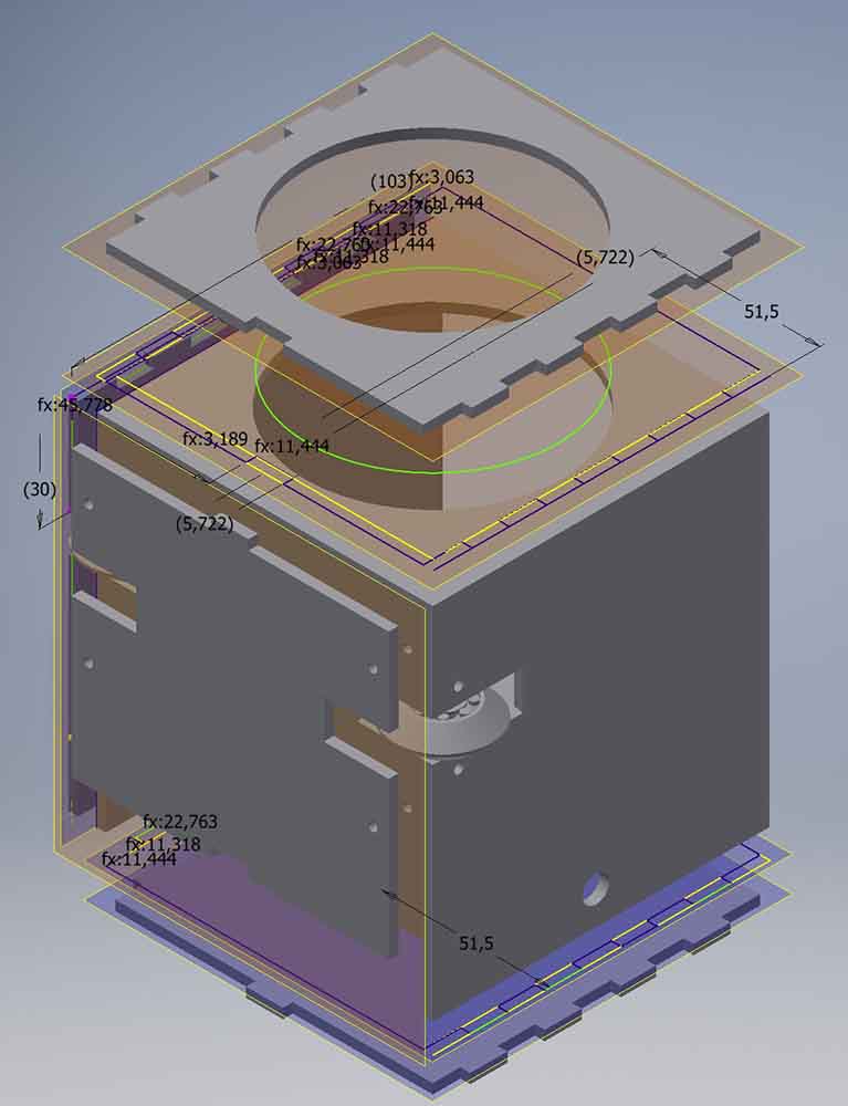
4 different sides were modelled. The left and right sides are identical, so only one of those are required to model. The side is then doubled in laser cutting.
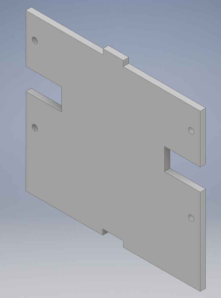
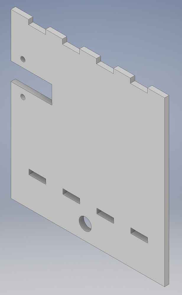
The cup holder was designed to move from side to side. If there are a lot of weight in the cup the holder needs a rail to move along without the cup holder to wiggle from the torque of the stepper motor.
To the back side a side loading bearing rail was designed. The bearing was designed in a way the rail can be only a 10mm height cut in the back MDF board. the V-shaped edges centers the bearing automatically and holds the bearing and therefore the cupholder upright.
The bearing was designed to be 3D printable on the place. None of the pieces touch each other and every piece stands on their own place on the build plate. The clearances have been checked for the Raise3D 3D Printer. But the clearances differ if the overhang and the angle of the print changes. So some experimenting is needed.
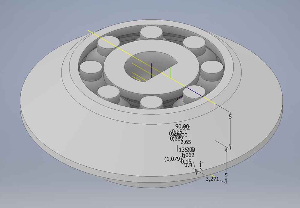
The inner structure of the bearing is in a way inlayed that the bearing can take load from an angle to the axle.
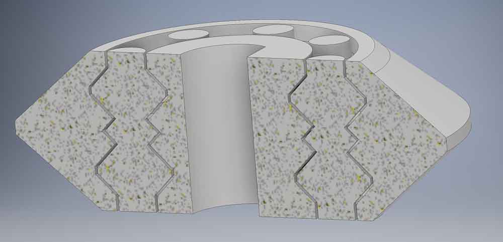
The bearings are held in place with 3D printed holders.
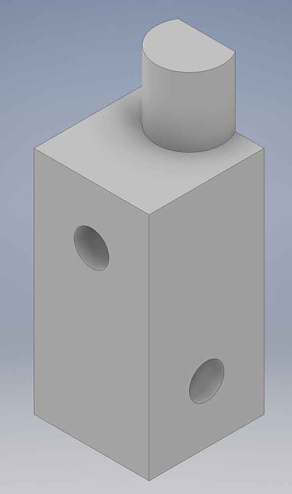
Two of these bearing holders are put against each other and the bearing sits in the middle. Four screws thought these holders holds the back of the cup holder in place. and anchors the whole cup holder together.
In a hurry the rest of the team measured the cup holder wrong, and made the rest of the case too small. The whole cup holder was scrapped and a new smaller more simple cup holder was designed.
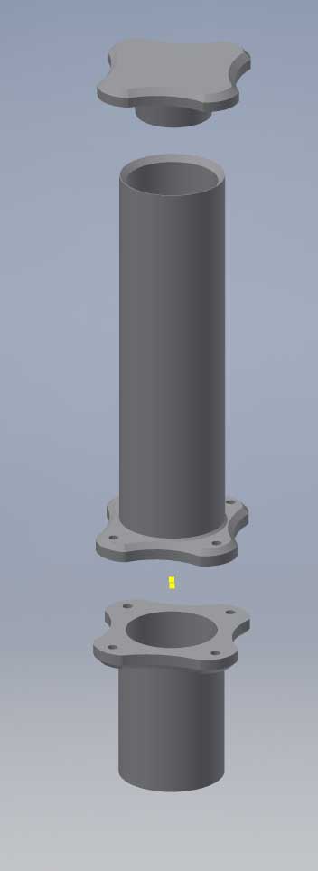
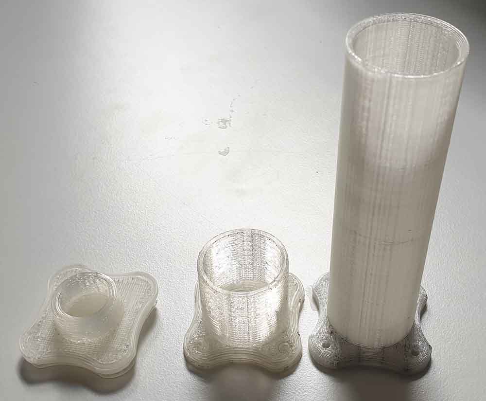
Tabled feeder tube
I also designed and 3D printed the tabled holder, and dispenser feeder and a dust cap for the tube.
Files
All my files can be found in my Gitlab repository