14. Networking and communications
Individual work.
“Design, build and connect wired or wireless node(s) with network or bus addresses.”
This week assignment I’m going to use my previous boards produced during weeks 7(Button+LED board) and 11(BuckArdu)
The system consists of NodeMCU ESP32, Button+LED board and Buckardu. From the ESP32 there is a serial bus going to the Button+LED and to the BuckArdu boards.
The nodes are connected as follows:
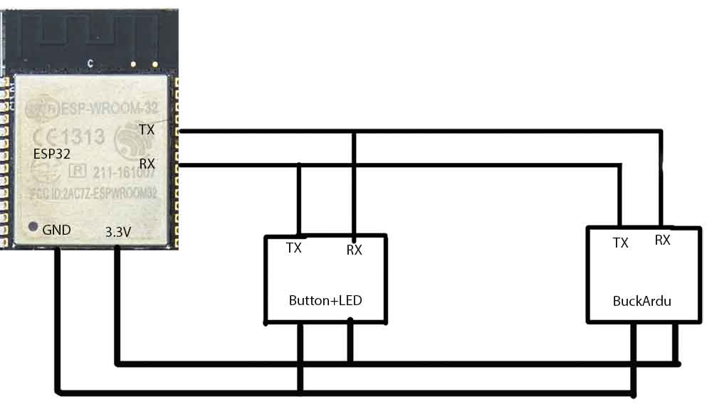
The transfer pin of the ESP32 is connected to the receive pins of the Attiny boards. And the receive pin is connected to the transfer pins of the Attiny boards. This is the serial Bus configuration.
The Attiny44A can work down to 1.8V So running it at 3.3V for this week is not a problem.
The ESP32 works as a serial Bluetooth bridge.
The Bluetooth bridge connects to the mobile phone or similar device. And sends the received commands to the serial bus. From the serial bus, the devices receive the commands and validate the message address. If the data is addressed to the given node, the node will perform the action according to the data.
For the smartphone Bluetooth controlling I used an app
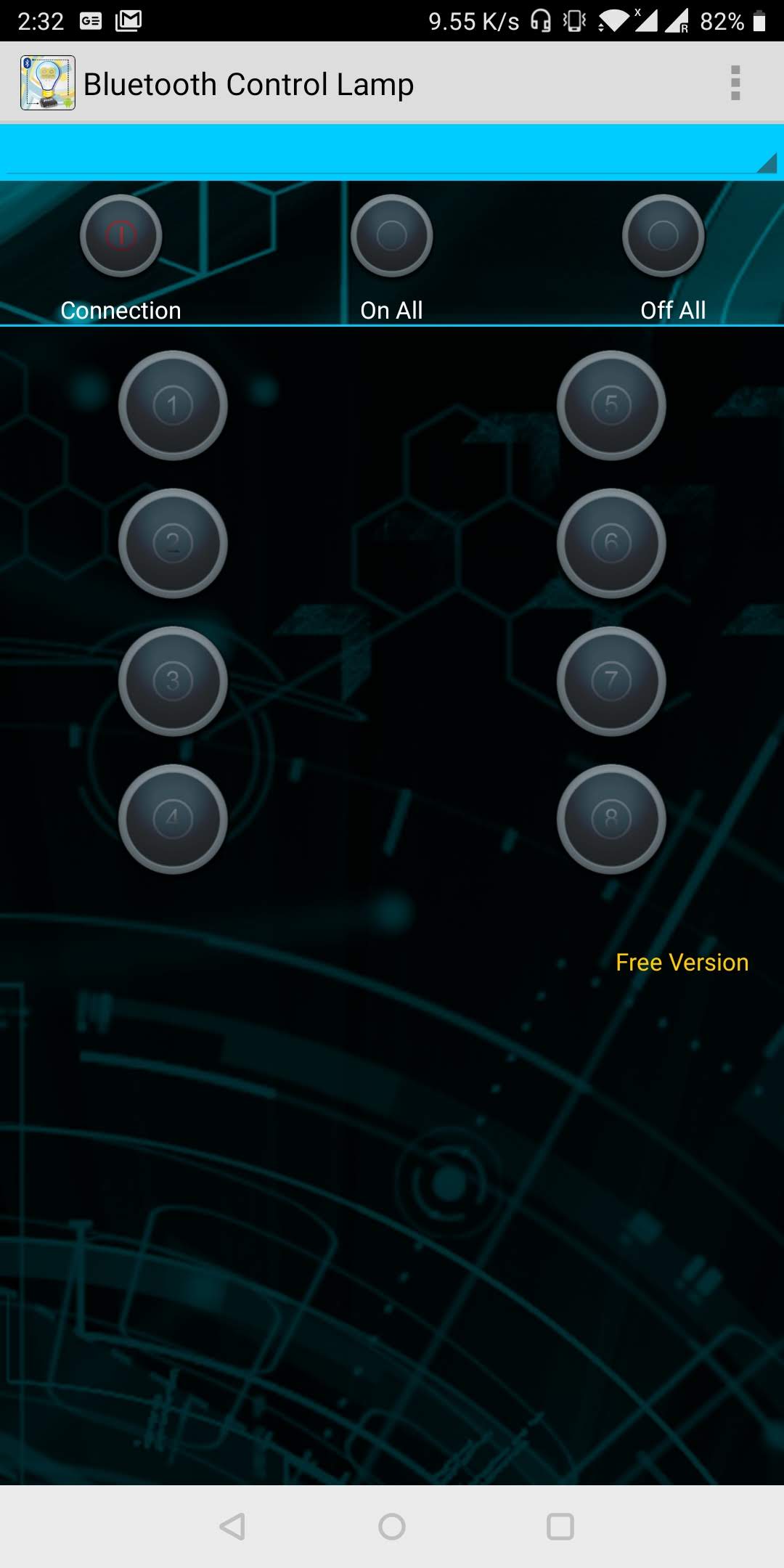
The app connects to the ESP32 via bluetooth and the buttons sends serial message when pressed on and a different message when pressed off. The serial data of the buttons:
| Button | Serial send on ON | Serial send on OFF |
|---|---|---|
| 1 | 1 | A |
| 2 | 2 | B |
| 3 | 3 | C |
| 4 | 4 | D |
| 5 | 5 | E |
| 6 | 6 | F |
| 7 | 7 | G |
| 8 | 8 | H |
These send bytes are then tested and assigned to different executions on the ATTiny boards.
The two boars are coded to control a LED. The Button+LED controls the onboard LED and onto the Buckardu’s regulated output a blue LED is soldered. From the output week, The Fast PWM is used to set the LEDs brightness on four different levels. For each brightness level, a different button is assigned. Buttons 1-4 control the Button+LED Board’s LED output and buttons 5-8 control the output of the Buckardu.
Code for the ESP32 Bluetooth bridge. This code is straight from the ESP32 Arduino IDE board manager examples.
//This example code is in the Public Domain (or CC0 licensed, at your option.)
//By Evandro Copercini - 2018
//
//This example creates a bridge between Serial and Classical Bluetooth (SPP)
//and also demonstrate that SerialBT have the same functionalities of a normal Serial

#include "BluetoothSerial.h"     // Libary for Bluetooth Serial use.

#if !defined(CONFIG_BT_ENABLED) || !defined(CONFIG_BLUEDROID_ENABLED)
#error Bluetooth is not enabled! Please run `make menuconfig` to and enable it
#endif

BluetoothSerial SerialBT;    //Start Bluetooth serial

void setup() {
  Serial.begin(9600);                //Start the serial connection to GBIO pins  1 and 3.  These pins will act like TX and RX.
  SerialBT.begin("ESP32test");   // Start Bluetooth and give Bluetooth device name
  Serial.println("The device started, now you can pair it with bluetooth!");
}

void loop() {                       //
  if (Serial.available()) {         // This evertything takes data from incoming serial
    SerialBT.write(Serial.read());  //  and passes it trough to Bluetooth.
  }                                 //
  if (SerialBT.available()) {       // This evertything takes data from incoming Bluetooth
    Serial.write(SerialBT.read());  //   and passes it trough to serial
  }
  delay(20);                        // Little delay. if run att full contionously the power consumption would rise unduly.
}
Code for BuckArdu
#include <util/delay.h> // Library to add delays. Necessary for blinking.
#include <avr/io.h> //Library to handle avr inputs and outputs


#include <SoftwareSerial.h>
SoftwareSerial mySerial(4, 5); // RX, TX

const char dim = '5'; // network address
const char dim2 = '6'; // network address
const char dim3 = '7'; // network address
const char dim4 = '8'; // network address These are the different commands that can come from the serial bus to perform action.

const char off = 'E'; // network address. Button 5 release will shut the LED down.
const int ledPin =  8; // the number of the LED pin ( = ATTiny pin 5)

int incomingByte;

void setup() {
  mySerial.begin(9600);


  DDRB = DDRB | (1 << PB2);                  // DDRB Port B Data Direction Register.  Selects direction of pins.
                                       // In this case, PB2 is an output

//these are for the PWM output,using the timer0:
DDRA      |=      (1<<DDB2);                           //setting the PWM pin to output.

TCCR0A    |=      (1<<WGM01);                    // set for Fast 8-bit PWM mode
TCCR0A    |=      (1<<WGM00);                    // set for Fast 8-bit PWM  mode
TCCR0A    |=      (1<<COM0A1);                   // Set OC0A on Compare MatchClear OC0A at BOTTOM (inverting mode). Driving N-channel mosfet.
TCCR0A    |=      (1<<COM0A0);                   // Set OC0A on Compare Match Clear OC0A at BOTTOM (inverting mode) Driving N-channel mosfet.
TCCR0B    |=      (1<<CS00);                    //  clk0/O/1 (No prescaling)try to go afap. this gives a freguency of 20 000 000hz/256= 78 125hz
TCCR0B    &=     ~(1<<CS01);                     //set CS01 to 0.


OCR0A = 255;                                   // start the PWM signal from 255 value (0-255 because of the 8-bit mode. 255 because of the inverted mode.)  P-MOSFET is off and no power is going through.

}

void loop() {
  if (mySerial.available() > 0) {           // take the infonmation from serial.

    incomingByte = mySerial.read();            //and write it memory.

    if (incomingByte == dim) {              //test if the recieved data was one of this nodes actions.

OCR0A = 30;                                 //adjust the Fast PWM trigger level accordingly.
 pinMode(5, OUTPUT); // open line to write  // send message back.
      mySerial.print("node ");
      mySerial.println(dim);
      pinMode(5, INPUT);


    }
  else if (incomingByte == dim2) {        //test if the recieved data was one of this nodes actions.

OCR0A = 20;                                 //adjust the Fast PWM trigger level accordingly.
 pinMode(5, OUTPUT); // open line to write
      mySerial.print("node ");    // send message back.
      mySerial.println(dim2);
      pinMode(5, INPUT);


    }

  else if (incomingByte == dim3) {

OCR0A = 10;
 pinMode(5, OUTPUT); // open line to write
      mySerial.print("node ");
      mySerial.println(dim3);
      pinMode(5, INPUT);


    }


  else if (incomingByte == dim4) {

OCR0A = 0;
 pinMode(5, OUTPUT); // open line to write
      mySerial.print("node ");
      mySerial.println(dim4);
      pinMode(5, INPUT);


    }

else if (incomingByte == off) {


                OCR0A = 255;  // turn led off

      pinMode(5, OUTPUT); // open line to write
      mySerial.print("node ");
      mySerial.println(dim);
      pinMode(5, INPUT);

    }
  }
}
Code for the Button+LED -board.
#include <util/delay.h> // Library to add delays. Necessary for blinking.
#include <avr/io.h> //Library to handle avr inputs and outputs


#include <SoftwareSerial.h>
SoftwareSerial mySerial(4, 5); // RX, TX

const char dim = '1'; // network addres
const char dim2 = '2'; // network addres
const char dim3 = '3'; // network addres
const char dim4 = '4'; // network addres

const char off = 'A'; // network addres
const int ledPin =  8; // the number of the LED pin ( = ATTiny pin 5)

int incomingByte;

void setup() {
  mySerial.begin(9600);

    pinMode(5, INPUT);
  DDRB = DDRB | (1 << PB2);                  // DDRB Port B Data Direction Register. Selects direction of pins
                                       // In this case PB2 is an output

//these are for the PWM output,using the timer0:
DDRA      |=      (1<<DDB2);                           //setting the PWM pin to output.

TCCR0A    |=      (1<<WGM01);                    // set for Fast 8-bit PWM mode
TCCR0A    |=      (1<<WGM00);                    // set for Fast 8-bit PWM  mode
TCCR0A    |=      (1<<COM0A1);                   // Set OC0A on Compare MatchClear OC0A at BOTTOM (inverting mode). Driving N-channel mosfet.
TCCR0A    |=      (1<<COM0A0);                   // Set OC0A on Compare Match Clear OC0A at BOTTOM (inverting mode) Driving N-channel mosfet.
TCCR0B    |=      (1<<CS00);                    //  clk0/O/1 (No prescaling)try to go afap. this gives a freguency of 20 000 000hz/256= 78 125hz
TCCR0B    &=     ~(1<<CS01);                     //set CS01 to 0.


OCR0A = 253;                                   // start the PWM signal from 255 value (0-255 because of the 8-bit mode. 255 because of the inverted mode.)  P-MOSFET is off and no power is going through.

}

void loop() {                               //The same as in Buckardu code.
  if (mySerial.available() > 0) {

    incomingByte = mySerial.read();

    if (incomingByte == dim) {

OCR0A = 250;
 pinMode(5, OUTPUT); // open line to write
      mySerial.print("node ");
      mySerial.println(dim);
      pinMode(5, INPUT);


    }
  else if (incomingByte == dim2) {

OCR0A = 200;
 pinMode(5, OUTPUT); // open line to write
      mySerial.print("node ");
      mySerial.println(dim);
      pinMode(5, INPUT);


    }

  else if (incomingByte == dim3) {

OCR0A = 126;
 pinMode(5, OUTPUT); // open line to write
      mySerial.print("node ");
      mySerial.println(dim);
      pinMode(5, INPUT);


    }


  else if (incomingByte == dim4) {

OCR0A = 0;
 pinMode(5, OUTPUT); // open line to write
      mySerial.print("node ");
      mySerial.println(dim);
      pinMode(5, INPUT);


    }

else if (incomingByte == off) {


                OCR0A = 255;  // turn led off

      pinMode(5, OUTPUT); // open line to write
      mySerial.print("node ");
      mySerial.println(dim);
      pinMode(5, INPUT);

    }
  }
}
After everything is connected the system works like planned.
Group assignment
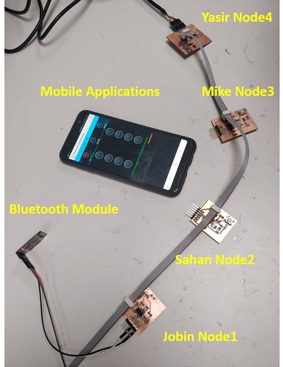
The group work was done together, four boards were used as separate nodes. The plan was to communicate with the Bluetooth module. We named the nodes as Jobin_Node1, Sahan_Node2, Mikel_ Node3, and Yasir_Node4. All the boards we programmed and connected serially, and controlled through Bluetooth application.
Target was to blink the LEDs on the boards when a button on the Bluetooth mobile application (Bluetooth Control Lamp) is pressed. The LED on each board lit up when the letter corresponding to the number assigned to the node was pressed. Finally, the code was modified so that all the LEDs turned on and off at the same time.
See the below picture of all separate boards connected using the serial bus and controlled wirelessly using Bluetooth module.
And a video how it works:
All the necessary files can be found on my gitlab page