3. Computer-Aided Design
Assignment
- Model (raster, vector, 2D, 3D, render, animate, simulate, …) a possible final project, and post it on your class page
Learning outcomes
- Evaluate and select 2D and 3D software.
Dyslexic proofread: This is perhaps meant to mean ” Evaluate and select 2D and 3D desinging software. As the question is given, I will evaluate minesweeper as good 2D program and Quake an OK 3D software. The documents Assessments are littered with tasks that are noncoherent in their interpretation. In the next question, the modeling part is described. - Demonstrate and describe processes used in modeling with 2D and 3D software
Have you
- Modeled experimental objects/part of a possible project in 2D and 3D software
Shown how you did it with words/images/screenshots
Included your original design files
1 Experience with modeling tools
I have used a variety of different designing programs:
- Sketchup Googles 3D modeling software for a wide range of drawing applications such as architectural, interior design, landscape architecture, civil and mechanical engineering, film and video game design. It is available as a web-based application, SketchUp Free,[4] a freeware version, SketchUp Make, and a paid version with additional functionality, SketchUp Pro.
- Blender is very powerful free and open-source 3D computer graphics software toolset used for creating animated films, visual effects, art, 3D printed models, interactive 3D applications and video games.
- Solidworks is a solid modeling computer-aided design (CAD) and computer-aided engineering (CAE) computer program.
- Fusion360 is 3D, CAD, CAM, and CAE tool that combines the workflow od multiple different tools to one convenient package.
- Inventor is Autodesk’s very powerful CAD application for 3D mechanical design, simulation, visualization, and documentation.
- Paint is a simple taster graphics editor in Microsoft Windows.
- Photoshop is an industry standard not only in raster graphics editing but in digital art as a whole.
- Gimp is a free and open-source raster graphics editor[4] used for image retouching and editing, free-form drawing, converting between different image formats, and more specialized tasks.
-
PILLOW Python Imaging Library is a free library for the Python programming language that adds support for opening, manipulating, and saving many different image file formats.
-
Some variety of little bit of everything. including: ProsGAN is a single image neural network GPU accelerated super-resolution image scaler. Can hallucinate extra resolution to images according to the taught set.
Modeling the final project with Inventor
For this week I modeled the enclosure for the lamp and tested the fitting of the PCB inside the closure.
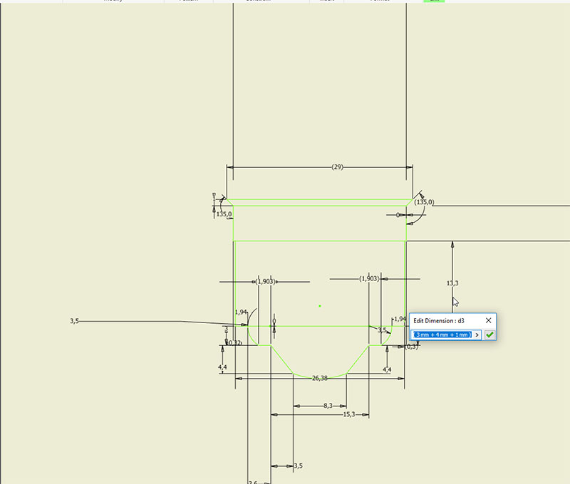
The 2D designing program Inventor 2019 Profesional was used to sketch an outline to E27 screw by the international standars
After the dimensionally accurate 2D vector sketch was exported using the export tool to a .jpg file. The export captures the working space as-is. so the framing needs to be accurate.
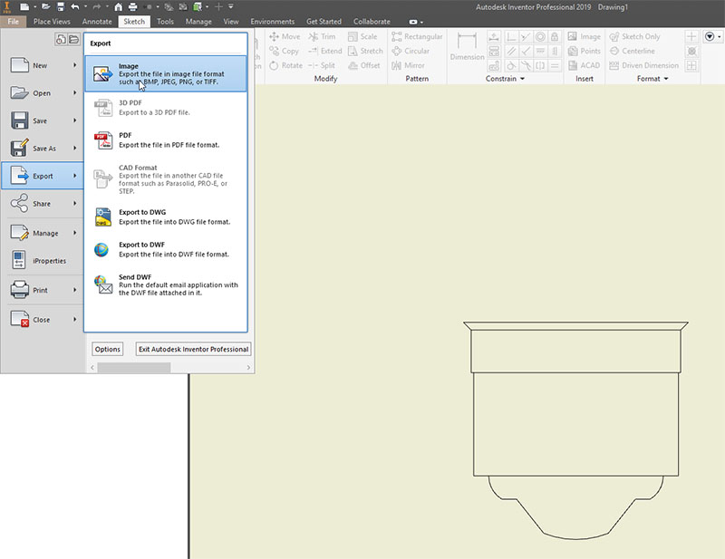
The 2D drawing export can be made in a variety of document styles: image, PDF, DWG, and other export styles can be added via plugins. For the next step, the sketch is exported in jpg form.
The E27 socket dimension image was turned into jpg by screenshotting the Inventor workspace and opening the image in GIMP. The selection tools were used to select the relevant area of the picture.
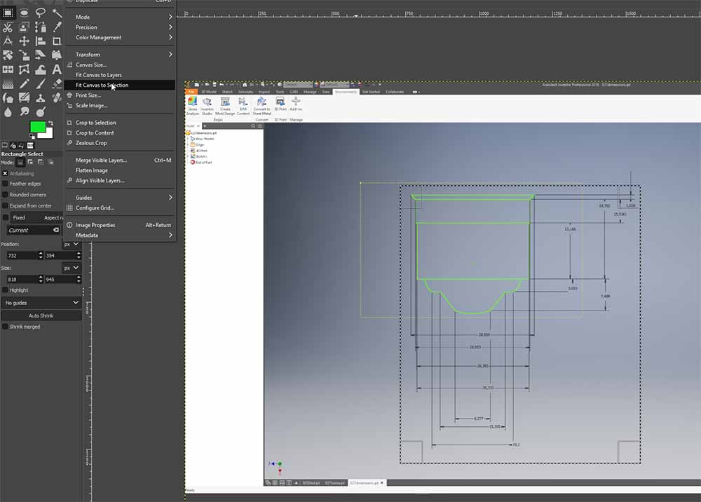 In the image drop-down menu, the Fit canvas to selection is used to crop the image to the selected size.
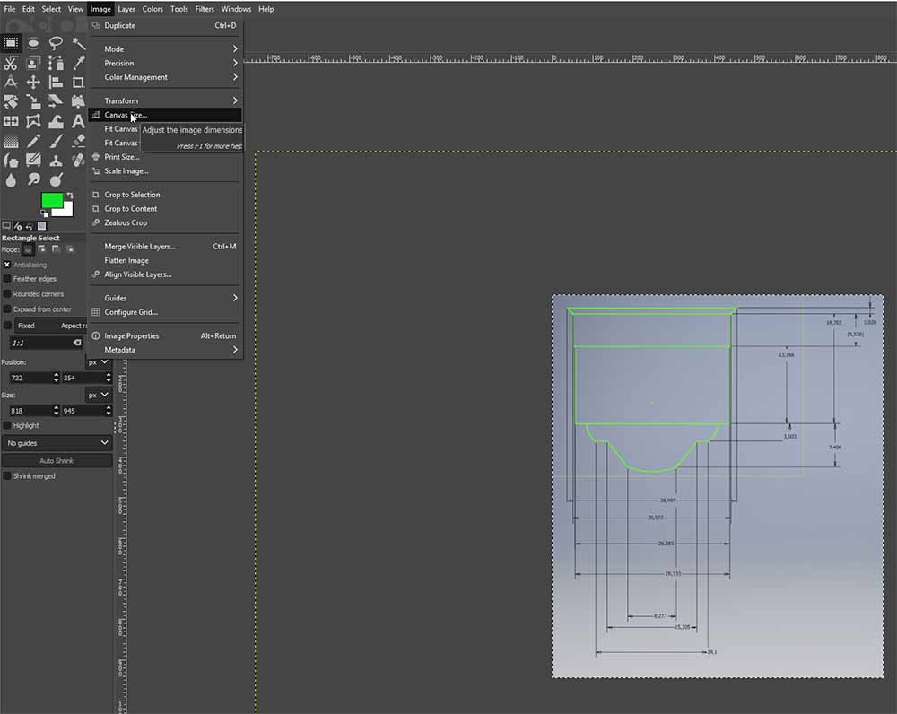 The remaining area is then set to wanted size in pixels by selecting the Canvas size.
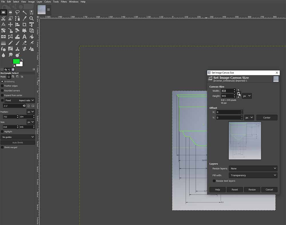 From this panel, the image dimensions can be set.
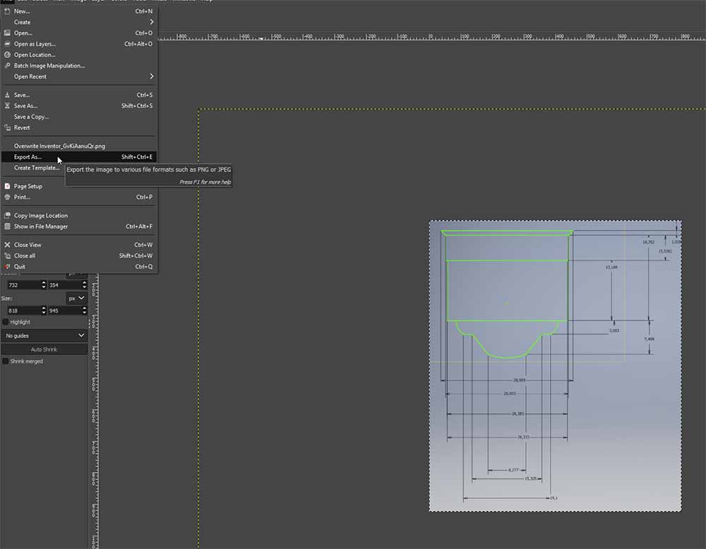 When the image consists of the needed area and is set to right dimensions it can be exported as jpg. This is selected from the File –> Export as.
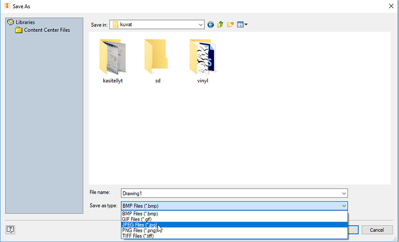
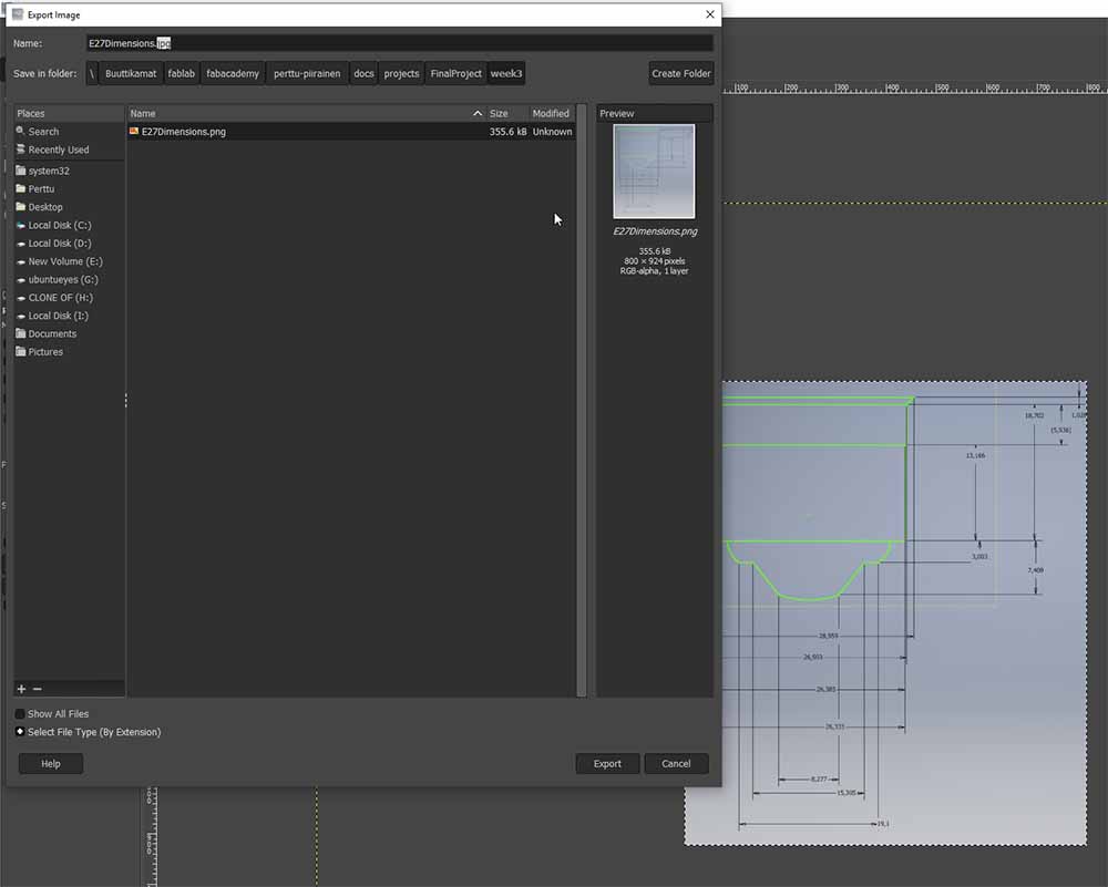 In the export menu, the name and the extension are set and The export button is pressed to get the export done.
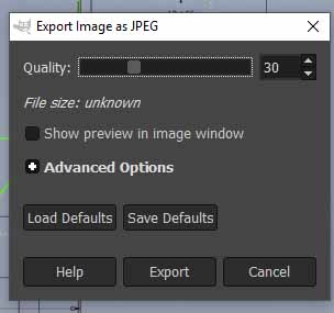 After selecting the jpg as exporting file the Gimp ask for compression level and other settings. The lower Quality number makes a smaller image size but drastically lowers the image quality.
Then the 27mm Edison screw, E27, was modelled in inventor 2019 Professional:
In the video can be seen the use of the 2D sketch to draw the outline for the E27. The first thing is to dimensionally lock the drawing itself. by making a dimensional line to known length. The step of drawing the outline beforehand in the 2D program is an extra step. The same sketch can be done straight in the 3D designing software Inventor 2019 Professional 3D design side. The 2D sketch drawing was done only in demonstration purposes.
The now redrawn sketch is partially revolved around a central axel to get around 3D shape. Around the cylinder shape, a coil is sketched. The coil dimensions and threads per inch (TPI) count is specified as standard. The coil is used to boolean subtract the coil shape put on the initial cylinder surface. This gives the screw part of the Edison screw. aka the treads of the socket.
The rest of the drawing is then brought to the 3rd dimension by revolving extrude. Afterward, the socket is made hollow by using the shell command. The material is then changed to appear metallic.
-
- Then the general shape of the bulb was drawn according to A19 standard.
-
- The PCB was fitted to the remaining volume inside the outer shape.
This time the 2D sketch part is merrily scrapped and the 3D part making is started from the part sketch itself. The dimensional drawing is the first dimension locked again using the line known length line method. an outline of the blub is sketched and revolved around center axel to the familiar light bulb shape. The bulb is done straight into a hollow form because the shell command occasionally does not work with complex geometries.
Over the bulb, a coil with 10mm spacing and 1mm of height with tread space of 11mm is sketched. This coil is used to cut a spiral form to the bulb. After this, the bulb mimics the designed led strip form to be used in the final project lamp. After a transparent poly lacto acid material is assigned to the bulb to reassemble the final product.
The same light bulb design sketch was used to draw the outline bor the PCB mockup for the lamp. A dimensionally correct PCB board and a dimension mock-ups are modeled. The material is changed to green ABS plastic to resemble the final product. The fitting to the inside 3D bulb is meticulously inspected. The inspection is done by making an assembly that all the parts are imported and the lamp is assembled as in the way it is going to be used. After dimensions check the final 3D modeled part is rendered using the Inventors own 3D render engine.
The lamp must be partially redesigned to be 3D printable and the PCB must fit inside the lamp. One possibility is to divide the outer wall into two halves.
In the lamp, the swirl is to use WS2812 led strip around the bulb to get the lightning.
Files
The files can be found on gitlab repository
.Previous work I have done in 2D and in 3D software.
I have designed various models using Inventor software.
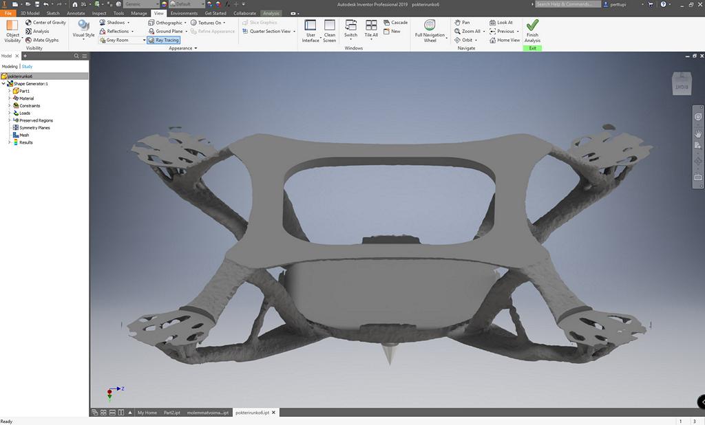
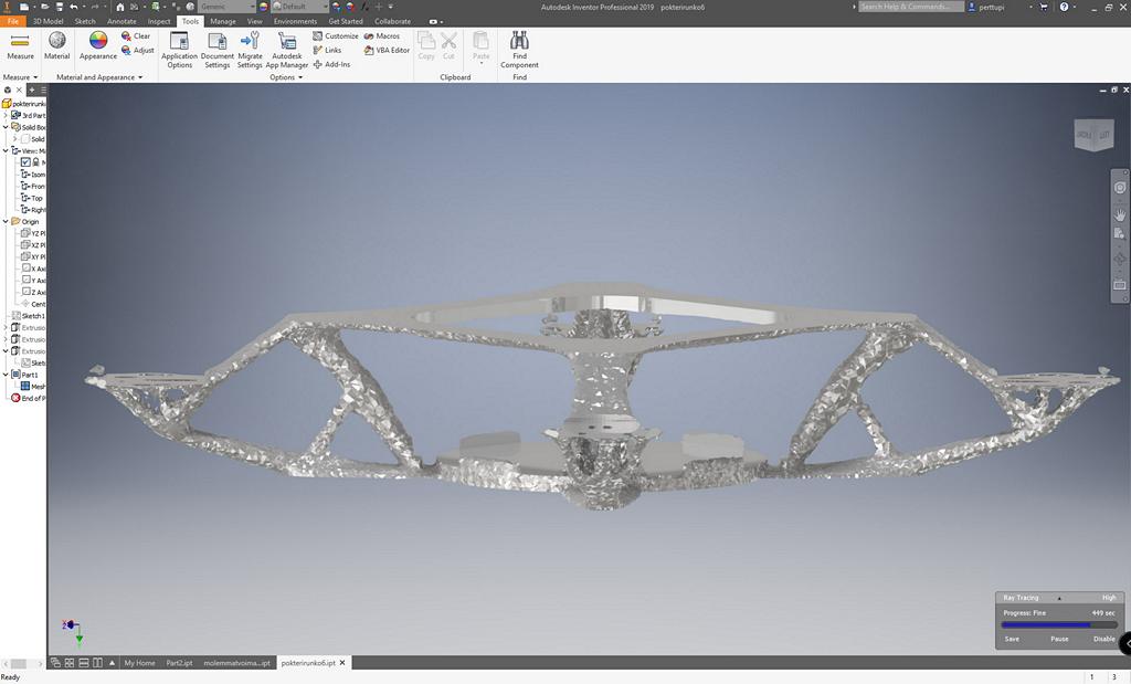
Force based generaded 3D-printable quadcopter chassis
I designed my Christmas cards using Inkscape and laser cut them from heavy cardboard using a laser cutter.
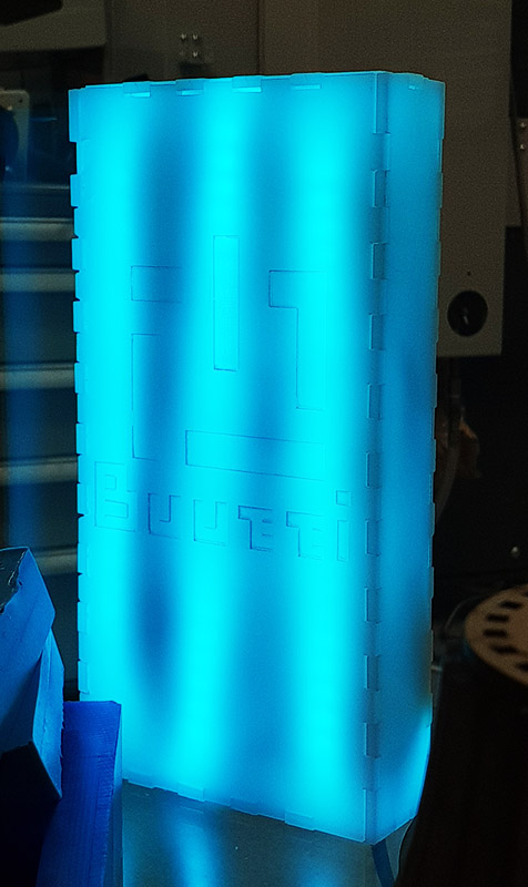
The Mobile Fab lab demo lamp was designed using Inkscape box maker. In the example, a logo is rasterized to the front face of the lamp. This is the lamp that we make in mobile Fablab. We have taught how to draw this lamp(without the logo) to 1600 school kids aged 12 to 17 years old.