14. Networking and Communication
NRF24L01+ and I2C OLED
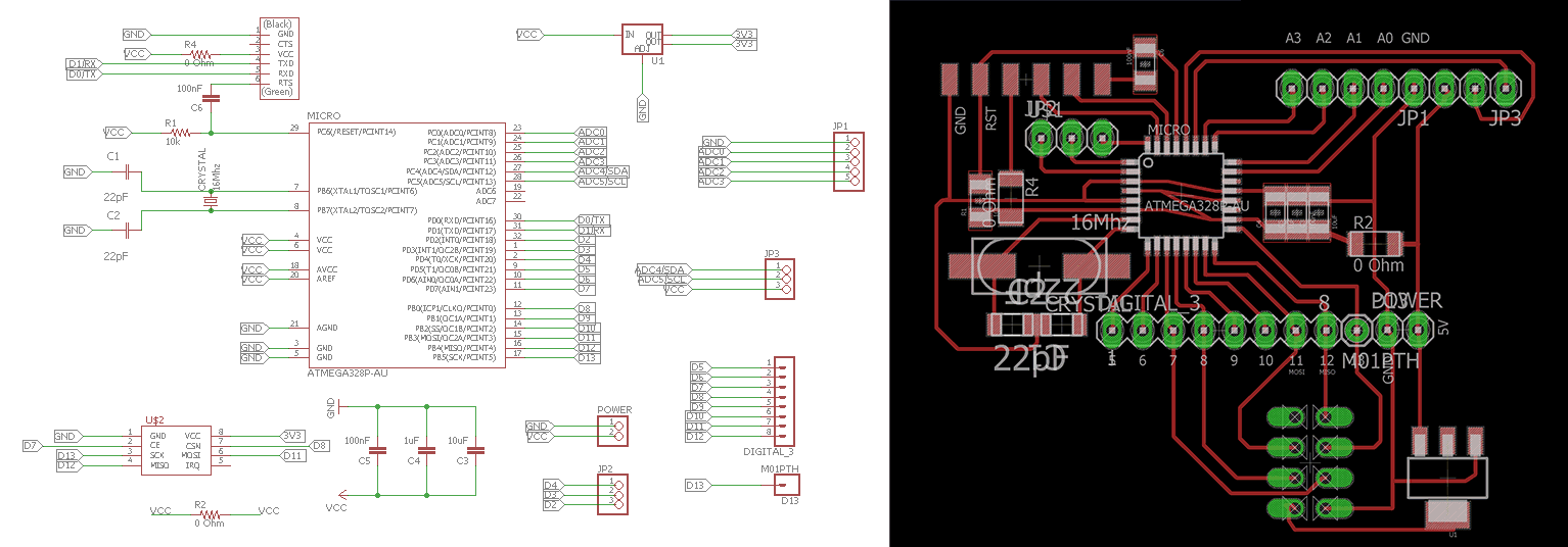
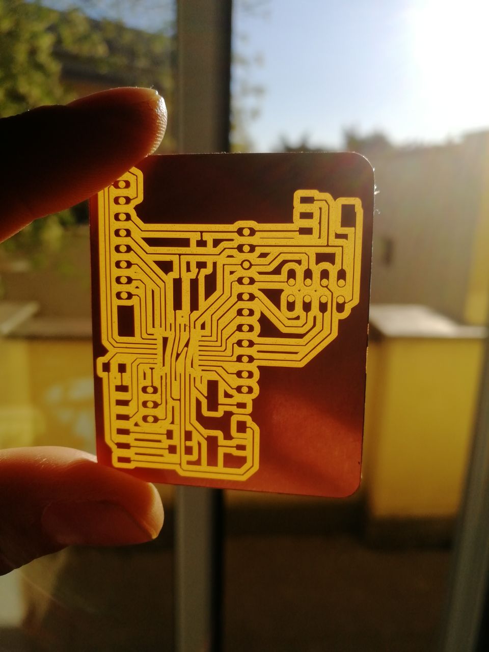
This week I decided to go with NRF24L01+ with the RF24 Arduino Library. After first tests made with my previous boards and an Arduino UNO, I implemented in a new board, using ATmega328P, the nRF24 for radio communication and a 0.91” 128x32 OLED connected trough I2C protocol.
There are other ways to talk to the NRF24L01 that you will find here http://playground.arduino.cc/InterfacingWithHardware/Nrf24L01
Here is how to wire the NRF24L01 to your boards, in my case I made my own with ATmega328p, which is the same as the Arduino UNO below.
https://github.com/TMRh20/RF24
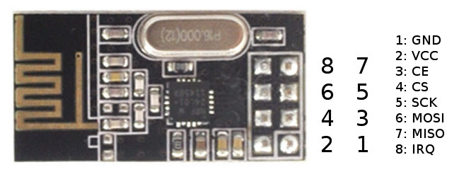
| PIN | NRF24L01+ | Arduino UNO | ATtiny25/45/85 | ATtiny44/84 |
|---|---|---|---|---|
| 1 | GND | GND | pin 4 | pin 14 |
| 2 | VCC | 3.3V | pin 8 | pin 1 |
| 3 | CE | D7 | pin 2 | pin 12 |
| 4 | CSN | D8 | pin 3 | pin 11 |
| 5 | SCK | D13 | pin 7 | pin 9 |
| 6 | MOSI | D11 | pin 6 | pin 7 |
| 7 | MISO | D12 | pin 5 | pin 8 |
| 8 | IRQ | - | - | - |
I used this site as my guide to program NRF24L01 with RF24
https://www.deviceplus.com/how-tos/arduino-guide/nrf24l01-rf-module-tutorial/
Note
The Chip can take 5V, there is no need to regulate the voltage, but to extend the life of the nRF24 I use a voltage regulator on the board, AMS1117 3.3
The New Board
As you can see, I’ve replaced the analog pins to facilitate the connections between the I2C-Oled and the board at the corresponding pins: GND - VCC - SCL - SDA. I also derived the pinout to directly attach the nf24 on the board.
Program the board
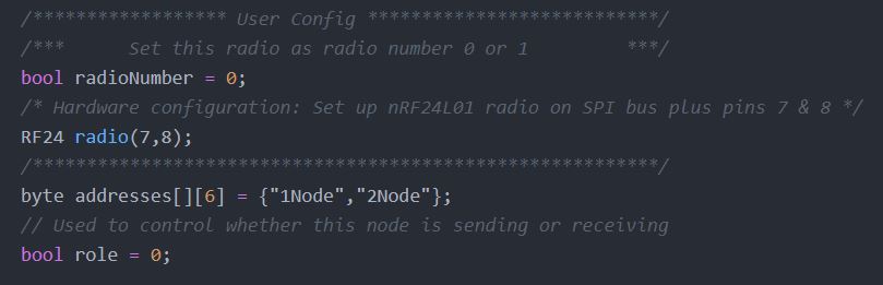
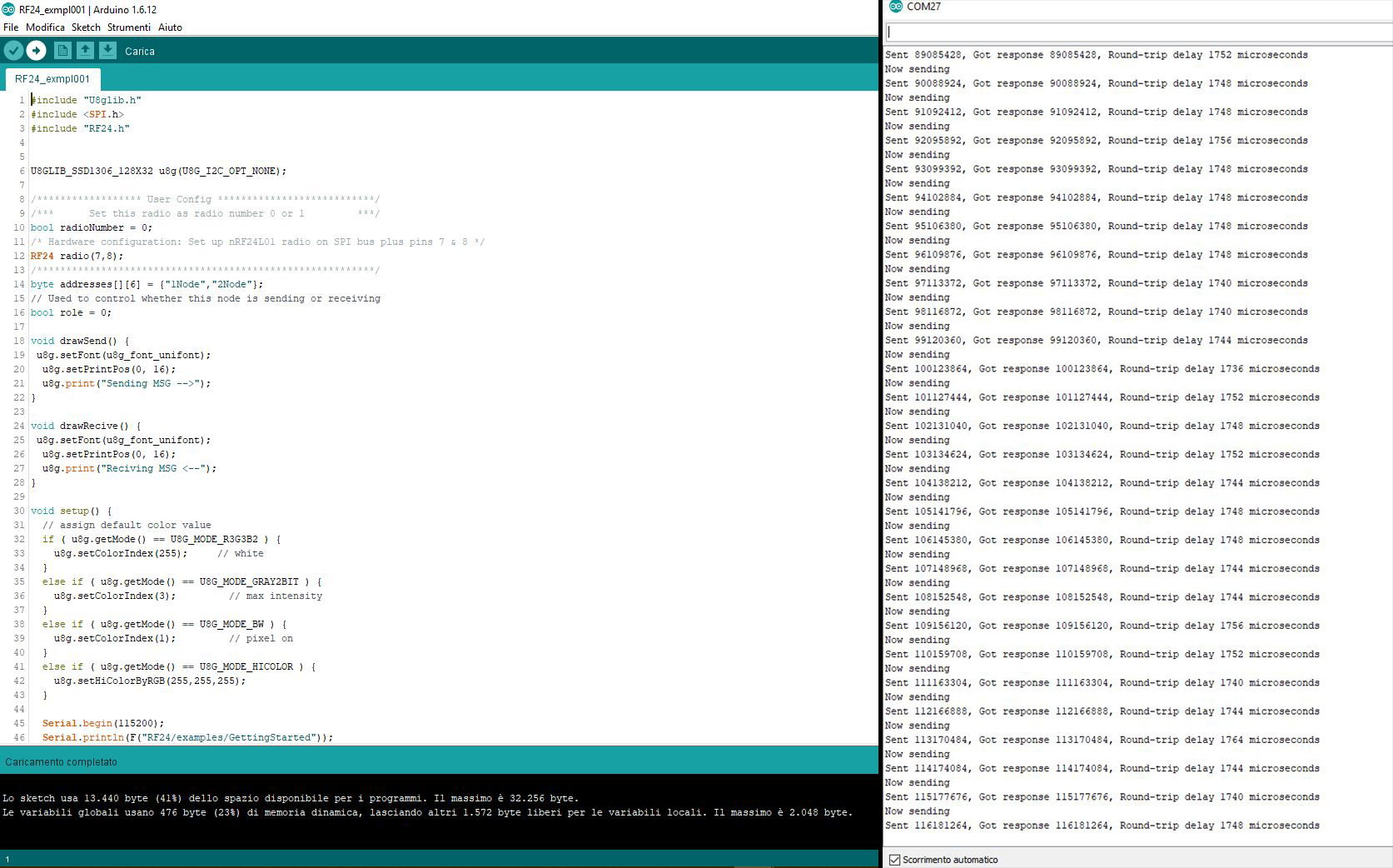
Through Arduino IDE I’ve made a Sketch as follows, implementing in it RF24.h, SPI.h and U8glib.h libraries:
#include "U8glib.h"
#include <SPI.h>
#include "RF24.h"


U8GLIB_SSD1306_128X32 u8g(U8G_I2C_OPT_NONE);

/****************** User Config ***************************/
/***      Set this radio as radio number 0 or 1         ***/
bool radioNumber = 0;
/* Hardware configuration: Set up nRF24L01 radio on SPI bus plus pins 7 & 8 */
RF24 radio(7,8);
/**********************************************************/
byte addresses[][6] = {"1Node","2Node"};
// Used to control whether this node is sending or receiving
bool role = 0;

void drawSend() {
 u8g.setFont(u8g_font_unifont);
  u8g.setPrintPos(0, 16);
  u8g.print("Sending MSG -->");
}

void drawRecive() {
 u8g.setFont(u8g_font_unifont);
  u8g.setPrintPos(0, 16);
  u8g.print("Reciving MSG <--");
}

void setup() {
  // assign default color value
  if ( u8g.getMode() == U8G_MODE_R3G3B2 ) {
    u8g.setColorIndex(255);     // white
  }
  else if ( u8g.getMode() == U8G_MODE_GRAY2BIT ) {
    u8g.setColorIndex(3);         // max intensity
  }
  else if ( u8g.getMode() == U8G_MODE_BW ) {
    u8g.setColorIndex(1);         // pixel on
  }
  else if ( u8g.getMode() == U8G_MODE_HICOLOR ) {
    u8g.setHiColorByRGB(255,255,255);
  }

  Serial.begin(115200);
  Serial.println(F("RF24/examples/GettingStarted"));
  Serial.println(F("*** PRESS 'T' to begin transmitting to the other node"));

  radio.begin();
  // Set the PA Level low to prevent power supply related issues since this is a
 // getting_started sketch, and the likelihood of close proximity of the devices. RF24_PA_MAX is default.
  radio.setPALevel(RF24_PA_LOW);

  // Open a writing and reading pipe on each radio, with opposite addresses
  if(radioNumber){
    radio.openWritingPipe(addresses[1]);
    radio.openReadingPipe(1,addresses[0]);
  }else{
    radio.openWritingPipe(addresses[0]);
    radio.openReadingPipe(1,addresses[1]);
  }

  // Start the radio listening for data
  radio.startListening();
}
void loop() {


/****************** Ping Out Role ***************************/
if (role == 1)  {

    radio.stopListening();                                    // First, stop listening so we can talk.


    Serial.println(F("Now sending"));

    unsigned long start_time = micros();                             // Take the time, and send it.  This will block until complete
     if (!radio.write( &start_time, sizeof(unsigned long) )){
       Serial.println(F("failed"));
     }

    radio.startListening();                                    // Now, continue listening

    unsigned long started_waiting_at = micros();               // Set up a timeout period, get the current microseconds
    boolean timeout = false;                                   // Set up a variable to indicate if a response was received or not

    while ( ! radio.available() ){                             // While nothing is received
      if (micros() - started_waiting_at > 200000 ){            // If waited longer than 200ms, indicate timeout and exit while loop
          timeout = true;
          break;
      }
    }

    if ( timeout ){                                             // Describe the results
        Serial.println(F("Failed, response timed out."));
    }else{
        unsigned long got_time;                                 // Grab the response, compare, and send to debugging spew
        radio.read( &got_time, sizeof(unsigned long) );
        unsigned long end_time = micros();

        // Spew it
        Serial.print(F("Sent "));
        Serial.print(start_time);
        Serial.print(F(", Got response "));
        Serial.print(got_time);
        Serial.print(F(", Round-trip delay "));
        Serial.print(end_time-start_time);
        Serial.println(F(" microseconds"));
    }
    // Try again 1s later
    delay(1000);
  }
/****************** Pong Back Role ***************************/
  if ( role == 0 )
  {
    unsigned long got_time;

    if( radio.available()){
                                                                    // Variable for the received timestamp
      while (radio.available()) {                                   // While there is data ready
        radio.read( &got_time, sizeof(unsigned long) );             // Get the payload
      }

      radio.stopListening();                                        // First, stop listening so we can talk
      radio.write( &got_time, sizeof(unsigned long) );              // Send the final one back.
      radio.startListening();                                       // Now, resume listening so we catch the next packets.

      Serial.print(F("Sent response "));
      Serial.println(got_time);
   }
 }
/****************** Change Roles via Serial Commands ***************************/
  if ( Serial.available() )
  {
    char c = toupper(Serial.read());
    if ( c == 'T' && role == 0 ){
      Serial.println(F("*** CHANGING TO TRANSMIT ROLE -- PRESS 'R' TO SWITCH BACK"));
      role = 1;                  // Become the primary transmitter (ping out)

    // picture loop
  u8g.firstPage();
  do {
    drawSend();
  } while( u8g.nextPage() );

   }else
    if ( c == 'R' && role == 1 ){
      Serial.println(F("*** CHANGING TO RECEIVE ROLE -- PRESS 'T' TO SWITCH BACK"));
       role = 0;                // Become the primary receiver (pong back)
       radio.startListening();

    // picture loop
  u8g.firstPage();
  do {
    drawRecive();
  } while( u8g.nextPage() );
    }
  }
} // Loop
Tip
Upload the compiled program on the two boards, but Remember to change the radioNumber from 0 to 1 for the second board that initially is the receiver.
Once connected the two boards to the their FTDI232 5v adapter,
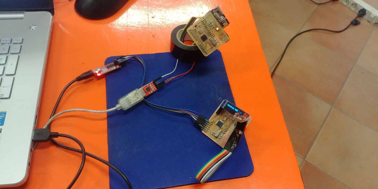
You can read the PING PONG feedbacks between two boards, and read it from the Serial Monitor on the FTDI serial COM connect to your PC:
And this is the Final Video: